Page is loading ...

CP9125
OBD II PocketScan
Code Reader
For use with OBD II Compliant Vehicles
1
2
3
4
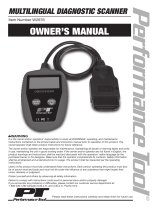
LCD Display - Is a Single Line Display with 8 characters.
ERASE Key - Used to Erase Trouble Codes and I/M
Monitor status from Vehicles Computer Modules and
scroll up through screens. (I/M Monitors are currently
used for state emissions tests.)
READ/Scroll Down Key - Used to view Read Codes, MIL
Status, I/M Readiness Status and Scroll down through
screens.
OBD II Connector - Used to communicate with OBD II
compliant vehicles.
1
2
3
4
0002-002-2666

Safety Precautions
For safety, read, understand and follow all safety messages
and instructions in manual before operating the PocketScan
TM
Code Reader.
Always refer to and follow safety messages and test
procedures provided by manufacturer of vehicle and
PocketScan
TM
Code Reader.
Signal Words Used:
Indicates a possible hazardous situation
which, if not avoided, will result in death or
serious injury to operator or bystanders.
Indicates a possible hazardous situation
which, if not avoided, could result in death
or serious injury to operator or bystanders.
Indicates a possible hazardous situation
which, if not avoided, may result in
moderate or minor injury to operator or
bystanders.
Indicates a condition which, if not avoided,
may result in damage to test equipment or
vehicle.
Important Safety Messages
Always wear ANSI approved eye protection.
Always operate vehicle in a well-ventilated area.
Always keep people, tools and test equipment away from all
moving or hot engine parts.
Always make sure vehicle is in PARK (automatic
transmission) or Neutral (manual transmission) and parking
brake is set.
Always block drive wheels and never leave vehicle
unattended while testing.
Always keep a fire extinguisher suitable for gasoline/
electrical/chemical fires readily available.
Never lay tools on vehicle battery.
!
WARNING
!
CAUTION
!
DANGER
IMPORTANT
2

3
Always use caution when working around ignition coil,
distributor cap, ignition wires, and spark plugs. Components
can produce a High Voltage while engine is running.
Battery acid is caustic. If contacted, rinse with water or
neutralize with a mild base (i.e. baking soda). If in eyes,
flush with water and call a physician immediately.
Never smoke or have open flames near vehicle. Vapors
from gasoline and battery during charge are explosive.
Never use the PocketScan
TM
Code Reader if internal
circuitry has been exposed to moisture. Internal shorts
could cause a fire and damage.
Always turn ignition key OFF when connecting or
disconnecting electrical components, unless otherwise
instructed.
Some vehicles are equipped with safety air bags. Follow
vehicle service manual cautions when working around air
bag components or wiring. Note, air bag can still open
several minutes after ignition key is off.
Always follow vehicle manufacturers warnings, cautions and
service procedures.

4
PocketScan
TM
Code Reader Features
Read Codes:
Reading Diagnostic Trouble Codes allows the PocketScan
TM
Code Reader to read the codes from the vehicles computer
modules.
Diagnostic Trouble Codes:
Diagnostic Trouble Codes are
used to help determine the cause
of a problem or problems with a
vehicle. Diagnostic Trouble Codes are set when a fault is
present for a sufficient amount of time.
Pending Codes: Pending
Codes are also referred to as
continuous monitor codes and
maturing codes. Pending
Codes occurs when the code
has not occurred a specific
number of times (depending on
vehicle,) causing the code to mature.
P0443
P0452
,
9
:
9
:

5
MIL Conditions:
MIL (Malfunction Indicator Lamp) Status displays the
state of the vehicles computer module(s).
MIL ON: Indicates that the
Malfunction Indicator Lamp on
vehicle should be ON indicating
a possible emissions problem.
√ If the MIL Status is ON and the MIL is not illuminated with
the engine running, then a problem exists in the MIL
circuit.
MIL OFF: Indicates the
Malfunction Indicator Lamp
should be off and there should
be no emission problems.
√ Some manufacturers will turn the MIL off if a certain
number of drive cycles occur without the same fault being
detected.
√ Diagnostic Trouble Codes related to a MIL are erased
from the computers memory after 40 warm-up cycles if
the same fault is not detected.
MIL ON
MIL OFF
9
:
9
:

Monitors Expanded Name
Misfire Misfire Monitor
Fuel Fuel System Monitor
Comp Comprehensive Components Monitor
Catlyst Catalyst Monitor
Htd Cat Heated Catalyst Monitor
Evap Evaporative System Monitor
Sec Air Secondary Air System Monitor
A/C Air Conditioning Refrigerant Monitor
O2 Snsr Oxygen Sensor Monitor
O2 Htr Oxygen Sensor Heater Monitor
EGR Exhaust Gas Recirculation
Status Description
Ready
Vehicle was driven enough under proper conditions to
complete the monitor.
Inc
(Incomplete) - Vehicle was not driven enough under
proper conditions to complete the monitor.
Inspection / Maintenance Monitors (I/M Monitors):
The I/M Monitors (Inspection / Maintenance) function displays
a SNAPSHOT of the operations for the Emission System.
√ After a specific amount of drive time (each monitor has
specific driving conditions and time required), the
computers monitors will decide if the vehicles emission
system is working correctly.
√ Some states MAY NOT require all monitors listed to be
Ready to pass the emissions test. Check with state
testing site for exact requirements. All states will fail a
vehicle that has the MIL Light lit at time of test.
Monitors Viewed:
Monitor Status:
Monitors may be cleared by:
− Using the erase codes function.
− Disconnected or discharged battery (on some vehicles.)
− Computer module losing power (on some vehicles.)
6

Reading Diagnostic Trouble Codes and Data
Avoid Cooling Fan! Fan may turn on
during test.
1.Turn Ignition Key to the Off Position.
2. Locate and Plug in Data Link
Connector (DLC.)
NOTE: The data link connector
should be located under
the dashboard on the
driverside of the vehicle.
If the data link connector is not located under the
dashboard as stated, a label describing the location of
the data link connector should be there.
3. Observe Display toggles between
Pocket and Scan.
NOTE: For a correct reading for
Diagnostic Trouble Codes and I/M Monitor Status,
ignition key must be in the ON position and Engine does
not require starting.
To get a correct reading for MIL Status, Engine must be
started.
4. Start Engine.
5. Press READ/Scroll Down Key
and Release.
O
F
F
O
N
!
WARNING
Pocket
7

NOTE: If diagnostic trouble codes (DTCs) are already being
displayed from a previous read operation, press and hold
READ/Scroll Down key for 3 seconds and release.
6.Observe a Moving
*
on Display.
NOTE: If a No Link message
displays, cycle ignition key to
the OFF position for 10
seconds, then back ON and repeat Reading Diagnostic
Data.
7. View Codes on Display
NOTE: If there are no codes present,
the tool will display 0
Codes and proceed to
display MIL Status when READ/Scroll Down is
pressed.
To View Codes press and
release READ/Scroll
Down key.
If the code is a Pending
Code a , will be displayed.
*
No Link
P0443
P0452
,
0 Codes9
3 Codes9
9
:
9
:
8

MIL ON
9
:
8. View MIL Status
Press and release
READ/Scroll Down
key.
9. View I/M Monitors that are
Incomplete.
Press and release
READ/Scroll Down
key.
NOTE: If there are no more I/M
Monitors that are Incomplete,
the tool will then display Ready
Monitors when READ/Scroll Down key is pressed.
10. View I/M Monitors that are Ready.
Press and release
READ/Scroll Down
key.
NOTE: Pressing the ERASE key will scroll up to review
Diagnostic Trouble Codes and Data.
NOTE: Holding READ /Scroll Down key for 3 seconds
will read Diagnostic Trouble Codes and Data again.
Monitrs
9
:
5 Ready
O2 Htr
2 Inc
Misfire
9
:
9
:
9
:
9
:
9

Erasing Diagnostic Trouble Codes and Data
Erasing allows the PocketScan
TM
Code Reader to delete the codes
and I/M Monitor status from the vehicles computer modules.
Only Erase Diagnostic Data after checking
system completely and writing down results.
Avoid Cooling Fan! Fan may turn on
during test.
1.Turn Ignition Key to the Off Position.
2. Locate and Plug in Data Link
Connector (DLC.)
NOTE: The data link connector
should be located under
the dashboard on the
driverside of the vehicle.
If the data link connector is not located under the
dashboard as stated, a label describing the location of
the data link connector should be there.
3. Observe Display toggles between
Pocket and Scan.
4.Turn Ignition Key to the ON Position
leaving Engine Off.
NOTE: Make sure that the Ignition Key is
ON and NOT in the Accessory
Position.
IMPORTANT
!
WARNING
O
F
F
O
N
O
F
F
O
N
Scan
10

5.Press and Hold ERASE Key for
3 Seconds and Release.
6.Observe ERASE? Displays.
7.Press and Hold ERASE Key
for 3 Seconds and Release.
8.Observe a Moving
-
on Display.
NOTE: If a NO LINK message
displays, cycle ignition key to
the OFF position for 10
seconds, then back ON, and
repeat Erasing Diagnostic Data.
9.Observe DONE Displays.
NOTE: If the problem causing Diagnostic Trouble Code(s) still
exists, the code will return. The Diagnostic Trouble
Code may return immediately or may return after vehicle
has been driven.
NOTE: Pressing READ /Scroll Down key will read
Diagnostic Trouble Codes and Data and Holding
ERASE key will erase results again.
11
ERASE?
-
DONE
NO LINK

Using Included CD
The Included CD is NOT required to use tool.
Some items included on the CD are:
o Manual included with tool.
o DTC Lookup Software.
o Adobe Acrobat Reader.
To be able to use the included CD the PC must
meet the following minimum requirements:
o 486 PC.
o 4 MB of RAM.
o Microsoft Windows 95 or Newer.
o CD ROM Drive.
o Adobe Acrobat Reader.
o Internet Explorer 4.0 or Higher.
o Minimum Screen Resolution of 800 x 600.
If resolution is 800 x 600, in Display Properties,
Settings Tab, Set Font Size to Small Fonts.
12

Running Applications On Included CD
1. Close All Programs on Computer.
2. Place Included CD in CD-Drive.
NOTE: If CD does not start automatically;
Select the Start button. Select
Run...Enter X:\Menu.Exe in
Open Box on Computer and
select OK.
NOTE: X is the CD-ROM drive letter
on the computer.
3. Observe Menu Appears.
4. Follow screen prompts on computer to run applications.
13

Diagnostic Trouble Codes (DTCs)
This section contains the J2012 Diagnostic Trouble Codes
(DTCs) as defined by the Society of Automotive Engineers (SAE).
Diagnostic Trouble Codes (DTCs) are recommendations not a
requirement. Manufacturers may not follow these, but most do.
Check vehicles service manual for DTC meaning if the code(s)
you are getting does not make sense.
Diagnostic Trouble Code (DTCs) definitions have been assigned
or reserved by the Society of Automotive Engineers (SAE) to
direct to proper service area(s).
Codes not assigned or reserved by the Society of Automotive
Engineers (SAE) are reserved for the manufacturer and referred
to as Manufacturer Specific Diagnostic Trouble Codes (DTCs).
Remember:
Visual inspections are important!
Problems with wiring and connectors are common,
especially for intermittent faults.
Mechanical problems (vacuum leaks, binding or
sticking linkages, etc.) can make a good sensor look
bad to the computer.
Incorrect information from a sensor may cause the
computer to control the engine in the wrong way. Faulty
engine operation might even make the computer show
a known good sensor as being bad!
NOTE: Additional DTC definitions can be obtained from the CD
supplied. If there are any problems operating the
supplied CD contact Customer Service
at 1(800) 228-7667.
14

15
Example:
P0101 - Mass or Volume Air Flow Circuit Range/Performance Problem
Powertrain Codes
P0xxx - Generic (SAE)
P1xxx - Manufacturer Specific
P2xxx - Generic (SAE)
P30xx-P33xx - Manufacturer Specific
P34xx-P39xx - Generic (SAE)
Chassis Codes
C0xxx - Generic (SAE)
C1xxx - Manufacturer Specific
C2xxx - Manufacturer Specific
C3xxx - Generic (SAE)
Body Codes
B0xxx - Generic (SAE)
B1xxx - Manufacturer Specific
B2xxx - Manufacturer Specific
B3xxx - Generic (SAE)
Network Communication Codes
U0xxx - Generic (SAE)
U1xxx - Manufacturer Specific
U2xxx - Manufacturer Specific
U3xxx - Generic (SAE)
Bx - Body
Cx - Chassis
Px - Powertrain
Ux - Network Comm.
x = 0, 1, 2 or 3
Vehicle Specific System
Specific Fault
Designation
P0101

16
P0001 Fuel Volume Regulator Control Circuit/Open
P0002 Fuel Volume Regulator Control CKT Range/Perf
P0003 Fuel Volume Regulator Control Circuit Low
P0004 Fuel Volume Regulator Control Circuit High
P0005 Fuel Shutoff Vlv. A Control Circuit/Open
P0006 Fuel Shutoff Vlv. A Control Circuit Low
P0007 Fuel Shutoff Vlv. A Control Circuit High
P0008 Engine Position System Performance (Bank 1)
P0009 Engine Position System Performance (Bank 2)
P0010 Camshaft Position Actuator A - Bank 1 Circuit Malfunction
P0011 Camshaft Position Actuator A - Bank 1 Timing Over-Advan.
P0012 Camshaft Position Actuator A - Bank 1 Timing Over-Retard
P0013 Camshaft Position Actuator B - Bank 1 Circuit Malfunction
P0014 Camshaft Position Actuator B - Bank 1 Timing Over-Advan.
P0015 Camshaft Position Actuator B - Bank 1 Timing Over-Retard
P0016 Cam/Crankshaft Pos. Correlation Sensor A - Bank 1
P0017 Cam/Crankshaft Pos. Correlation Sensor B - Bank 1
P0018 Cam/Crankshaft Pos. Correlation Sensor A - Bank 2
P0019 Cam/Crankshaft Pos. Correlation Sensor B - Bank 2
P0020 Camshaft Position Actuator A - Bank 2 Circuit Malfunction
P0021 Camshaft Position Actuator A - Bank 2 Timing Over-Advan.
P0022 Camshaft Position Actuator A - Bank 2 Timing Over-Retard
P0023 Camshaft Position Actuator B - Bank 2 Circuit Malfunction
P0024 Camshaft Position Actuator B - Bank 2 Timing Over-Advan.
P0025 Camshaft Position Actuator B - Bank 2 Timing Over-Retard
P0026 Intake Valve-Bank 1 Control Solenoid CKT Range/Perf
P0027 Exhaust Valve-Bank1 Control Solenoid CKT Range/Perf
P0028 Intake Valve-Bank 2 Control Solenoid CKT Range/Perf
P0029 Exhaust Valve-Bank2 Control Solenoid CKT Range/Perf
P0030 HO2S Bank 1 Sen 1 Heater Circuit
P0031 HO2S Bank 1 Sen 1 Heater Circuit Low
P0032 HO2S Bank 1 Sen 1 Heater Circuit High
P0033 Turbo/Sup Wastegate Control Circuit
P0034 Turbo/Sup Wastegate Control Circuit Low
P0035 Turbo/Sup Wastegate Control Circuit High
P0036 HO2S Bank 1 Sen 2 Heater Circuit
P0037 HO2S Bank 1 Sen 2 Heater Circuit Low
P0001 - P0074

17
P0038 HO2S Bank 1 Sen 2 Heater Circuit High
P0039 Turbo/Super Charger Bypass Cntrl CKT Performance
P0040 O2 Bank 1 Sensor 1 Signals Swapped w/ O2 Bank 2 Sensor 1
P0041 O2 Bank 1 Sensor 2 Signals Swapped w/ O2 Bank 2 Sensor 2
P0042 HO2S Bank 1 Sen 3 Heater Circuit
P0043 HO2S Bank 1 Sen 3 Heater Circuit Low
P0044 HO2S Bank 1 Sen 3 Heater Circuit High
P0045 Turbo/Super Boost Ctrl Solenoid A Circuit/Open
P0046 Turbo/Super Boost Ctrl Solenoid A CKT Range/Perf
P0047 Turbo/Super Boost Ctrl Solenoid A Circuit Low
P0048 Turbo/Super Boost Ctrl Solenoid A Circuit High
P0049 Turbo/Super Boost Input/Turbine Speed Overspeed
P0050 HO2S Bank 2 Sen 1 Heater Circuit
P0051 HO2S Bank 2 Sen 1 Heater Circuit Low
P0052 HO2S Bank 2 Sen 1 Heater Circuit High
P0053 HO2S Bank 1 Sen 1 Heater Resistance
P0054 HO2S Bank 1 Sen 2 Heater Resistance
P0055 HO2S Bank 1 Sen 3 Heater Resistance
P0056 HO2S Bank 2 Sen 2 Heater Circuit
P0057 HO2S Bank 2 Sen 2 Heater Circuit Low
P0058 HO2S Bank 2 Sen 2 Heater Circuit High
P0059 HO2S Bank 2 Sen 1 Heater Resistance
P0060 HO2S Bank 2 Sen 2 Heater Resistance
P0061 HO2S Bank 2 Sen 3 Heater Resistance
P0062 HO2S Bank 2 Sen 3 Heater Circuit
P0063 HO2S Bank 2 Sen 3 Heater Circuit Low
P0064 HO2S Bank 2 Sen 3 Heater Circuit High
P0065 Air Assisted Injec. Control Range/Performance
P0066 Air Assisted Injec. Control Circuit Low
P0067 Air Assisted Injec. Control Circuit High
P0068 MAF/MAP Sensor Throttle Position Correlation
P0069 MAP/BARO Correlation
P0070 Ambient Air Temp. Sensor Circuit
P0071 Ambient Air Temp. Sensor Range/Performance
P0072 Ambient Air Temp. Sensor Circuit Low
P0073 Ambient Air Temp. Sensor Circuit High
P0074 Ambient Air Temp. Sensor CKT Intermittent

18
P0075 Intake Valve-Bank 1 Control Circuit
P0076 Intake Valve-Bank 1 Control Circuit Low
P0077 Intake Valve-Bank 1 Control Circuit High
P0078 Exhaust Valve-Bank1 Control Circuit
P0079 Exhaust Valve-Bank1 Control Circuit Low
P0080 Exhaust Valve-Bank1 Control Circuit High
P0081 Intake Valve-Bank 2 Control Circuit
P0082 Intake Valve-Bank 2 Control Circuit Low
P0083 Intake Valve-Bank 2 Control Circuit High
P0084 Exhaust Valve-Bank2 Control Circuit
P0085 Exhaust Valve-Bank2 Control Circuit Low
P0086 Exhaust Valve-Bank2 Control Circuit High
P0087 Fuel Rail Pressure Too Low
P0088 Fuel Rail Pressure Too High
P0089 Fuel Pressure Reg 1 Performance
P0090 Fuel Pressure Reg 1 Control Circuit
P0091 Fuel Pressure Reg 1 Control Circuit Low
P0092 Fuel Pressure Reg 1 Control Circuit High
P0093 Fuel System Leak (Large)
P0094 Fuel System Leak (Small)
P0095 IAT Sensor 2 Circuit
P0096 IAT Sensor 2 CKT Range/Perf
P0097 IAT Sensor 2 Circuit Low
P0098 IAT Sensor 2 Circuit High
P0099 IAT Sensor 2 CKT Intermittent
P0100 MAF or VAF A Circuit Malfunction
P0101 MAF or VAF A CKT Range/Perf
P0102 MAF or VAF A Circuit Low Input
P0103 MAF or VAF A Circuit High Input
P0104 MAF or VAF A CKT Intermittent
P0105 MAP/BARO Circuit Malfunction
P0106 MAP/BARO CKT Range/Perf
P0107 MAP/BARO Circuit Low Input
P0108 MAP/BARO Circuit High Input
P0109 MAP/BARO CKT Intermittent
P0110 IAT Sensor Circuit Malfunction
P0111 IAT Sensor 1 CKT Range/Perf
P0075 - P0148

19
P0112 IAT Sensor 1 Circuit Low Input
P0113 IAT Sensor 1 Circuit High Input
P0114 IAT Sensor 1 CKT Intermittent
P0115 Engine Coolant Temp Circuit Malfunction
P0116 Engine Coolant Temp CKT Range/Perf
P0117 Engine Coolant Temp Circuit Low Input
P0118 Engine Coolant Temp Circuit High Input
P0119 Engine Coolant Temp CKT Intermittent
P0120 TPS/Pedal Position Sensor A Circuit Malfunction
P0121 TPS/Pedal Position Sensor A CKT Range/Perf
P0122 TPS/Pedal Position Sensor A Circuit Low Input
P0123 TPS/Pedal Position Sensor A Circuit High Input
P0124 TPS/Pedal Position Sensor A CKT Intermittent
P0125 Clsd Loop Fuel Ctrl Insufficient Coolant Temp
P0126 Coolant Temp Insufficient Stable Operation
P0127 IAT Sensor Too High
P0128 Coolant Temp Below Thermostat Regulating Temp
P0129 Barometric Pressure Too Low
P0130 O2 Sensor Circuit Malfunction (Bank 1 Sensor 1)
P0131 O2 Sensor Circuit Low Volts (Bank 1 Sensor 1)
P0132 O2 Sensor Circuit High Volts (Bank 1 Sensor 1)
P0133 O2 Sensor CKT Slow Response (Bank 1 Sensor 1)
P0134 O2 Sensor CKT No Activity (Bank 1 Sensor 1)
P0135 O2 Sensor Heater Circuit Malfunction (Bank 1 Sensor 1)
P0136 O2 Sensor Circuit Malfunction (Bank 1 Sensor 2)
P0137 O2 Sensor Circuit Low Volts (Bank 1 Sensor 2)
P0138 O2 Sensor Circuit High Volts (Bank 1 Sensor 2)
P0139 O2 Sensor CKT Slow Response (Bank 1 Sensor 2)
P0140 O2 Sensor CKT No Activity (Bank 1 Sensor 2)
P0141 O2 Sensor Heater Circuit Malfunction (Bank 1 Sensor 2)
P0142 O2 Sensor Circuit Malfunction (Bank 1 Sensor 3)
P0143 O2 Sensor Circuit Low Volts (Bank 1 Sensor 3)
P0144 O2 Sensor Circuit High Volts (Bank 1 Sensor 3)
P0145 O2 Sensor CKT Slow Response (Bank 1 Sensor 3)
P0146 O2 Sensor CKT No Activity (Bank 1 Sensor 3)
P0147 O2 Sensor Heater Circuit Malfunction (Bank 1 Sensor 3)
P0148 Fuel Delivery Malfunction

20
P0149 Fuel Timing Malfunction
P0150 O2 Sensor Circuit Malfunction (Bank 2 Sensor 1)
P0151 O2 Sensor Circuit Low Volts (Bank 2 Sensor 1)
P0152 O2 Sensor Circuit High Volts (Bank 2 Sensor 1)
P0153 O2 Sensor CKT Slow Response (Bank 2 Sensor 1)
P0154 O2 Sensor CKT No Activity (Bank 2 Sensor 1)
P0155 O2 Sensor Heater Circuit Malfunction (Bank 2 Sensor 1)
P0156 O2 Sensor Circuit Malfunction (Bank 2 Sensor 2)
P0157 O2 Sensor Circuit Low Volts (Bank 2 Sensor 2)
P0158 O2 Sensor Circuit High Volts (Bank 2 Sensor 2)
P0159 O2 Sensor CKT Slow Response (Bank 2 Sensor 2)
P0160 O2 Sensor CKT No Activity (Bank 2 Sensor 2)
P0161 O2 Sensor Heater Circuit Malfunction (Bank 2 Sensor 2)
P0162 O2 Sensor Circuit Malfunction (Bank 2 Sensor 3)
P0163 O2 Sensor Circuit Low Volts (Bank 2 Sensor 3)
P0164 O2 Sensor Circuit High Volts (Bank 2 Sensor 3)
P0165 O2 Sensor CKT Slow Response (Bank 2 Sensor 3)
P0166 O2 Sensor CKT No Activity (Bank 2 Sensor 3)
P0167 O2 Sensor Heater Circuit Malfunction (Bank 2 Sensor 3)
P0168 Engine Fuel Temperature Too High
P0169 Fuel Composition Incorrect
P0170 Fuel Trim Malfunction (Bank 1)
P0171 System Too Lean (Bank 1)
P0172 System Too Rich (Bank 1)
P0173 Fuel Trim Malfunction (Bank 2)
P0174 System Too Lean (Bank 2)
P0175 System Too Rich (Bank 2)
P0176 Fuel Compensation Sensor Circuit Malfunction
P0177 Fuel Compensation Sensor CKT Range/Perf
P0178 Fuel Compensation Sensor Circuit Low Input
P0179 Fuel Compensation Sensor Circuit High Input
P0180 Fuel Temperature Sensor A Circuit Malfunction
P0181 Fuel Temperature Sensor A CKT Range/Perf
P0182 Fuel Temperature Sensor A Circuit Low Input
P0183 Fuel Temperature Sensor A Circuit High Input
P0184 Fuel Temperature Sensor A CKT Intermittent
P0185 Fuel Temperature Sensor B Circuit Malfunction
P0149 - P0222
/