
Op er ating In struc tions
Con veyor Hop per
SSK-3
016-3MS
Ster ling Ma te rial Pro cess ing

Tech ni cal ser vice:
Ser vice de part ment
Tele phone: (800) 423-3183
Edi tion: 12/97
016-3MS
SSK-3
2
These op er at ing in struc tions are for:*
(* Please fill in per son ally)
Se ri al num ber:
Built in:
Date of de li very:
Num ber of de li very:
Date of com mis sio ning:
Lo ca ti on:
Group of ma chi nes:
Ster ling Ma te rial Pro cess ing
5200 West Clinton Ave.
Mil wau kee, WI 53223
Tele phone: (414) 354-0970
Fax: (414) 354-6421
www.sterlco.com

Ster ling Ma te rial Pro cess ing re tains all rights to change the in for ma tion in these
op er at ing in struc tions at any time with out no tice.
We as sume no li a bil ity for any er rors or di rect or in di rect dam age re sult ing in con -
text with these op er at ing in struc tions.
Copying, trans la tion or pub li ca tion in any form ex cept for per sonal use of pur -
chaser re quires ap proval from Ster ling Ma te rial Pro cess ing.
All rights re served.
016-3MS
SSK-3
3

Please note that our address and phone information has changed.
Please reference this page for updated contact information.
These manuals are obsolete and are provided only for their technical information, data and capacities.
Portions of these manuals detailing procedures or precautions in the operation, inspection, maintenance
and repair of the products may be inadequate, inaccurate, and/or incomplete and shouldn’t be relied
upon. Please contact the ACS Group for more current information about these manuals and their
warnings and precautions.
Parts and Service Department
The ACS Customer Service Group will provide your company with genuine OEM quality parts manufactured to engineering
design specifications, which will maximize your equipment’s performance and efficiency. To assist in expediting your phone
or fax order, please have the model and serial number of your unit when you contact us. A customer replacement parts list
is included in this manual for your convenience. ACS welcomes inquiries on all your parts needs and is dedicated to
providing excellent customer service.
For immediate assistance, please contact:
• North, Central and South America, 8am – 5pm CST +1 (800) 483-3919 for drying, conveying, heating and cooling
and automation. For size reduction: +1 (800) 229-2919.
North America, emergencies after 5pm CST (847) 439-5855
North America email: [email protected]
• Mexico, Central & South America
Email: acslatinamericacustserv@corpemail.com
• Europe, Middle East & Africa +48 22 390 9720
Email: acseuropecustserv@corpemail.com
• India +91 21 35329112
Email: acsindiacustserv@corpemail.com
• Asia/Australia +86 512 8717 1919
Email: acsasiacustser[email protected]
Sales and Contracting Department
Our products are sold by a worldwide network of independent sales representatives. Contact our Sales Department for the
name of the sales representative nearest you.
Let us install your system. The Contract Department offers any or all of these services: project planning; system packages
including drawings; equipment, labor, and construction materials; and union or non-union installations.
For assistance with your sales or system contracting needs please Call:
North, Central and South America +1
(
262
)
641-8600 or +1 (847) 273-7700 Monday–Friday, 8am–5pm CST
Europe/Middle East/Africa +48 22 390 9720
India +91 21 35329112
Asia/Australia +86 512 8717 1919
Facilities:
ACS offers facilities around the world to service you no matter where you are located. For more information, please visit us at
www.acscorporate.com
United States:
ACS Schaumburg – Corporate Offices
1100 E. Woodfield Road
Suite 588
Schaumburg, IL 60173
Phone: + 1 847 273 7700
Fax: + 1 847 273 7804
ACS New Berlin – Manufacturing Facility
2900 S. 160
th
Street
New Berlin, WI 53151
Phone : +1 262 641 8600
Fax: + 1 262 641 8653
Asia/Australia:
ACS Suzhou
109 Xingpu Road SIP
Suzhou, China 215126
Phone: + 86 8717 1919
Fax: +86 512 8717 1916
Europe/Middle East/Africa:
ACS Warsaw
Ul. Działkowa 115
02-234 Warszawa
Phone: + 48 22 390 9720
Fax: +48 22 390 9724
India
ACS India
Gat No. 191/1, Sandbhor Complex
Mhalunge, Chakan, Tal Khed,
Dist. Pune 410501, India
Phone: +91 21 35329112
Fax: + 91 20 40147576

Tab le of con tents
1. Sa fe ty in struc tions ............................................5
1.1. War nings and sym bols ..................................6
1.2. Ex pla na tions and in for ma ti on .............................7
1.3. For your sa fe ty ........................................8
1.4. For the sa fe ty of the equip ment ...........................8
2. In stal la ti on in struc tions ........................................9
2.1. Trans port ............................................10
2.2. Set-up ..............................................10
2.3. Com pres sed-air supp ly (only with com pres sed-air val ves) ....12
2.4. Elec tri cal con nec ti on...................................13
3. Functio nal des crip ti on ........................................15
4. Main ten an ce.................................................16
4.1. Main ten an ce in ter vals..................................18
4.2. Dis as sem bling the hop per ..............................19
4.2.1. Re pla ce the sea ling rings .......................21
4.2.2. Ad just the flap switch ..........................23
4.2.3. Clea ning the hop per ...........................24
5. Spa re parts list ..............................................25
6. Tech ni cal data ...............................................27
6.1. Di men si on sheet ......................................27
016-3MS
SSK-3
Ta ble of con tents 4

1. Safety in struc tions
»
These safety in struc tions ap ply to all per sons within the range of
ac tion of the equip ment.
Please in form all per sons within the range of ac tion of the equip -
ment of the di rect and in di rect haz ards con nected with the
equip ment.
These op er at ing in struc tions are to be used by all per sons as -
signed ac tiv i ties con nected with the equip ment.
Knowl edge of the Eng lish lan guage is pre req ui site.
En sure in each case that the op er at ing per son nel are fa mil iar
with the op er at ing in struc tions and the func tion of the equip -
ment.
Ob serve the safety in struc tions of the con nected con vey ing
sys tem.
016-3MS
SSK-3
Safety in struc tions 5

1.1. Warn ings and sym bols
The fol low ing warn ings and sym bols are used in these op er at ing in struc tions:
»
This sym bol in di cates dan ger to life! Fa tal or se ri ous in jury is
pos si ble if the cor re spond ing in struc tions, reg u la tions or warn -
ings are not ob served.
L
This sym bol in di cates that se ri ous in jury is pos si ble if the cor -
re spond ing in struc tions, reg u la tions or warn ings are not ob -
served.
F
This sym bol in di cates that ex ten sive dam age to equip ment is
pos si ble if the cor re spond ing in struc tions, reg u la tions or
warn ings are not ob served.
&
This sym bol in di cates in for ma tion im por tant for be com ing fa -
mil iar with the equip ment, i.e. tech ni cal cor re la tions.
$
This sym bol in di cates that a tech ni cal term is ex plained at this
point.
016-3MS
SSK-3
Safety in struc tions 6

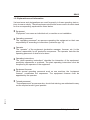
1.2. Ex pla na tions and in for ma tion
Var i ous terms and des ig na tions are used fre quently in these op er at ing in struc -
tions to en sure clar ity. There fore please note that the terms used in the text stand
for the cor re spond ing ex pla na tions listed be low.
·
Equipment
“Equipment” can mean an individual unit, a machine or an installation.
·
Operating personnel
The “operating personnel” are persons operating the equipment on their own
responsibility or according to instructions (minimum age: 16).
·
Operator
The “operator” of the equipment (production manager, foreman, etc.) is the
person responsible for all production sequences. The operator instructs the
operating personnel of what is to be done.
·
Operating instructions
The “plant operating instructions” describe the interaction of the equipment,
production sequences or methods. The plant operating instructions must be
compiled by the operator of the equipment.
·
Equipment foreman
When several operating personnel work on one machine, the “equipment
foreman” coordinates the sequences. The equipment foreman must be
appointed by the operator.
·
Trained personnel
“Trained personnel” are persons who, due to their training, are authorized to carry
out the required work in good practice.
016-3MS
SSK-3
Safety in struc tions 7

1.3. For your safety
·
It is absolutely necessary that you observe the operating instructions for the
corresponding conveying system.
·
The device is intended exclusively for conveying plastic granules and regrind.
Any other usage is not permitted.
·
This device is not suitable for processing foods.
·
Before beginning maintenance work, set all compressed air piping on the device
at zero pressure. Danger of accidents!
·
The device may only be operated if all corresponding components have been
properly connected and are in accordance with the relevant regulations.
1.4. For the safety of the equip ment
·
It is absolutely necessary that you observe the operating instructions for the
corresponding conveying system.
·
For the operation of the hoppers, a compressed-air supply is necessary.
·
Never set the operating pressure of the hoppers at more than 6 bar (system
overpressure).
·
Install the hoppers in such a way that the outlet flap is hinged in a right angle to the
direction of movement of the machine.
·
Make sure that all plugs are connected properly.
·
Observe the carrying capacity of the machine flange.
016-3MS
SSK-3
Safety in struc tions 8

2. In stal la tion in struc tions
»
These in stal la tion in struc tions are in tended for per sons with
skills in elec tri cal and me chan i cal ar eas due to their train ing, ex -
pe ri ence and re ceived in struc tions.
Per son nel us ing these in stal la tion in struc tions must be in -
structed in the reg u la tions for the pre ven tion of ac ci dents, the
op er at ing con di tions and safety reg u la tions and their im ple men -
ta tion.
En sure in each case that the per son nel are in formed.
The in stal la tion in struc tions pro vided in the cor re spond ing op er -
at ing in struc tions ap ply for all con nected equip ment.
Ob serve safety reg u la tions with re gard to lift ing gear han dling.
All in stal la tion work must be car ried out with the equip ment dis -
con nected from elec tri cal power and com pressed air sup ply.
L
For in stal la tion work tak ing place at heights of over approx.
1828.8 mm (6 ft.), use only lad ders or sim i lar equip ment and
work ing plat forms in tended for this pur pose. At greater
heights, the proper equip ment for pro tec tion against fall ing
must be worn.
Use only suit able lift ing gear which is in proper work ing or der
and load sus pen sion de vices with suf fi cient car ry ing ca pac -
ity. Do not stand or work un der sus pended loads!
Use suit able work shop equip ment
In stall the equip ment such that all parts are eas ily ac ces si ble;
this fa cil i tates main te nance and re pair work.
016-3MS
SSK-3
In stal la tion in struc tions 9

2.1. Trans port
For trans port, only the ap pro pri ate lift ing gear should be used (e.g. fork lift or
work shop crane).
»
Ob serve the car ry ing ca pac ity of the lift ing gear.
Ob serve the safety in struc tions for the han dling of lift ing gear.
2.2. Set-up
The ar range ment of the hop per load ers may vary de pend ing on the type of de -
vice to be con veyed on and the ma te rial used. Fas ten ing onto fixed ma chine
throats is pro vided by means of strap re tain ers. How ever, ad di tional sup port of
the hop per loader is nec es sary if the de vices are not suf fi ciently ca pa ble of bear -
ing the load.
016-3MS
SSK-3
In stal la tion in struc tions 10
J
L
As sem bly

Mount the hop per loader in such a way that the out let flap swings in a right-hand
an gle to the di rec tion of ma chine move ment. Please check dur ing as sem bly that
the ad mis si ble bear ing loads are not ex ceeded.
Please check that all con nect ing points are tight to en sure that the con vey ing per -
for mance is not im paired.
It should more over be ob served, par tic u larly if cus tom pro duced con nect ing parts
are used, that the ma te rial dis charged from the hop per loader must nei ther get
into the open nor must it clog the fil ter sur faces (ob serve an gle of re pose!).
F
Do not ex ces sively load in let noz zle of hop per loader,
re move hose sep a rately, if nec es sary!
016-3MS
SSK-3
In stal la tion in struc tions 11

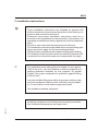
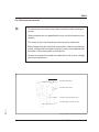
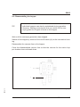
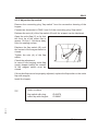
2.3. Com pressed-air sup ply (only with com pressed-air valves)
For op er at ing the con trol valves, a
com pressed-air sup ply is nec es -
sary.
Check com pressed-air pip ing for
cor rect in stal la tion and as sem bly.
Check fit tings, length and qual ity of
the hose con nec tions for agree -
ment with re quire ments.
The op er at ing pres sure is 5-6 bar
(72.52-87.02 PSI) (sys tem
overpressure).
Check the com pressed-air sup -
plied by the plant’s sup ply net work.
Ad just com pressed-air pres sure to
5-6 bar (72.52-87.02 PSI) (sys tem overpressure).
Com pressed air must be dewatered and oiled.
In stall a main te nance unit (pres sure re ducer with wa ter sep a ra tor and oiler) if re -
quired.
Con nect the unit to the plant’s sup ply net work by means of a hose.
L
Depressurize com pressed-air sup ply lines which must be
opened.
F
Com pressed air must be dewatered and oiled.
Ad just pres sure to a max. value of 6 bar (87.02 PSI) (sys tem
overpressure).
016-3MS
SSK-3
In stal la tion in struc tions 12
Main te nance unit

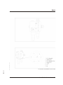
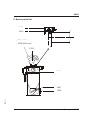
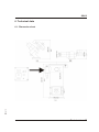
2.4. Elec tri cal con nec tion
»
The elec tri cal con nec tion may only be car ried out by trained per -
son nel.
Other per sons are not per mit ted to carry out the elec tri cal con -
nec tion.
The rules of the lo cal elec tric ity board must be ob served.
Be fore be gin ning the elec tri cal con nec tion, make sure that the
mains volt age and the power fre quency are in ac cor dance with
the data on the name plate of the de vice.
All work may only be car ried out when the unit is at zero volt age
and at zero pres sure.
016-3MS
SSK-3
In stal la tion in struc tions 13
Plug con nec tion con nec tion hous ing hop per
Con nec ti on point di aphragm val ve (SV)
Con nec ti on point SKW
Con nec ti on point pro be
Con nec ti on plug “flap switch (KL)”
Con nec ti on plug “con vey or con trol”

016-3MS
SSK-3
In stal la tion in struc tions 14

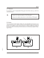
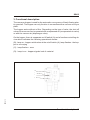
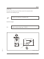
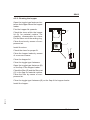
3. Func tional de scrip tion
The con veyor hop per is used for the au to matic con vey ance of freely flow ing plas -
tic gran ules. The hop per can only func tion in con nec tion with a vac uum con veyor
plant.
The hop per works with out a fil ter. De pending on the type of valve, the shut-off
valve of the vac uum line is op er ated with com pressed air (com pressed-air valve)
or with the vac uum air (di a phragm valve).
On the hop per, there is a sep a rate on/off switch (A) and a func tion con trol ling de -
vice which in di cates the fol low ing op er a tional modes:
(B): lamp on - hop per switched on at the on/off switch (A); lamp flashes - the hop -
per is con vey ing
(C): lamp flashes - er ror
(D): lamp is on - hop per sig nals lack of ma te rial
016-3MS
SSK-3
Func tional de scrip tion 15
Con nec tion hous ing hop per
B
A
C
D

4. Main te nance
»
This chap ter is in tended for per sons with skills in elec tri cal and
me chan i cal ar eas due to their train ing, ex pe ri ence and re ceived
in struc tions.
Per son nel us ing the in struc tions in this chap ter must be in -
structed of the reg u la tions for the pre ven tion of ac ci dents, the
op er at ing con di tions and safety reg u la tions and their im ple men -
ta tion.
En sure in each case that the per son nel are in formed ac cord -
ingly.
For main te nance work tak ing place at heights of over approx.
1828.8 mm (6 ft.), use only lad ders or sim i lar equip ment and
work ing plat forms in tended for this pur pose. At greater heights,
the proper equip ment for pro tec tion against fall ing must be
worn.
Use only suit able lift ing gear which is in proper work ing or der
and load sus pen sion de vices with suf fi cient car ry ing ca pac ity.
Do not stand or work un der sus pended loads!
En sure that the elec tric mo tors/switch cab i nets are suf fi ciently
pro tected against mois ture.
Use only suit able work shop equip ment.
Be fore start ing main te nance work, ap point a su per vi sor.
In form the re spon si ble per son nel be fore main te nance work on
the sys tem is started.
Never op er ate the equip ment when par tially dis man tled.
All main te nance and re pair work not de scribed in this chap ter
may only be car ried out by Ster ling ser vice per son nel or au tho -
rized per son nel (ap pointed by Ster ling).
016-3MS
SSK-3
Main te nance 16

L
Dis con nect the equip ment from mains sup ply be fore start ing
main te nance pro ce dures to en sure that it can not be switched
on un in ten tion ally.
Depressurize all com pressed air pip ing of the equip ment be -
fore start ing main te nance work.
F
Please ob serve the main te nance in ter vals.
Be fore start ing main te nance work, clean the equip ment of oil,
fuel or lu bri cants.
En sure that ma te ri als and in ci den tals re quired for op er a tion
as well as spare parts are dis posed of prop erly and in an en vi -
ron men tally sound man ner.
Use only orig i nal Ster ling spare parts.
Keep re cord of all main te nance and re pair pro ce dures.
016-3MS
SSK-3
Main te nance 17

4.1. Main te nance in ter vals
Daily: Check warn ing signs on equip ment for good
leg i bil ity and com plete ness.
With com pressed-air valve:
check the oil level in the oiler
empty the wa ter sep a ra tor
check the op er at ing pres sure in the fac tory
ductwork sys tem
(max. 6 bar (87.02 PSI) sys tem overpressure)
Ev ery six months: Check all elec tri cal and me chan i cal
con nec tions for proper fit
Check the set tings of the level probes
Check the seal ing rings on the lock ing flaps
Yearly: Re place the seal ing rings on the lock ing flaps
016-3MS
SSK-3
Main te nance 18

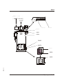
4.2. Dis as sem bling the hop per
&
In di vid ual hop pers can also be main tained dur ing op er a tion.
How ever, Ster ling rec om mends that you switch off the con -
vey ing plant for all types of work on the hop per.
Wait un til the con vey ing pro ce dure has stopped.
Switch off the hop per by means of the on/off switch (A) on the con nec tion hous -
ing.
Dis as sem ble the vac uum line on the hop per.
Close the dis as sem bled vac uum line so that the vac uum for the ac tive hop -
per-load ers does not break down.
016-3MS
SSK-3
Main te nance 19
Con nec tion hous ing hop per
A
B
Page is loading ...
Page is loading ...
Page is loading ...
Page is loading ...
Page is loading ...
Page is loading ...
Page is loading ...
Page is loading ...
-
 1
1
-
 2
2
-
 3
3
-
 4
4
-
 5
5
-
 6
6
-
 7
7
-
 8
8
-
 9
9
-
 10
10
-
 11
11
-
 12
12
-
 13
13
-
 14
14
-
 15
15
-
 16
16
-
 17
17
-
 18
18
-
 19
19
-
 20
20
-
 21
21
-
 22
22
-
 23
23
-
 24
24
-
 25
25
-
 26
26
-
 27
27
-
 28
28


Ask a question and I''ll find the answer in the document
Finding information in a document is now easier with AI
Related papers
Other documents
-
 ACS A0565547 User manual
-
Sterling Plumbing Septic System 882.00253.00 User manual
-
Alcatel Carrier Internetworking Solutions 046-3MS User manual
-
Sterling Plumbing Plumbing Product SKW-E User manual
-
Sterling Plumbing 882.00254.00 User manual
-
 Mitsubishi Electronics 882.00207.00 User manual
-
NetSafety SSK-5 and UN-MK-3 Sunshade and Universal Mounting Kit Owner's manual
-
Conair CHS-810 User manual
-
-
 ACS Marine Sanitation System XFC-S User manual


