Page is loading ...

8 CHANNEL/
16 CHANNEL DVR
User Manual
SDE-400x/SDE-500x

Copyright
©2012 Samsung Techwin Co., Ltd. All rights reserved.
Trademark
is the registered logo of Samsung Techwin Co., Ltd.
The name of this product is the registered trademark of Samsung Techwin Co., Ltd.
Other trademarks mentioned in this manual are the registered trademark of their respective company.
Restriction
Samsung Techwin Co., Ltd shall reserve the copyright of this document. Under no circumstances, this document shall be reproduced, distributed or
changed, partially or wholly, without formal authorization of Samsung Techwin.
Disclaimer
Samsung Techwin makes the best to verify the integrity and correctness of the contents in this document, but no formal guarantee shall be provided.
Use of this document and the subsequent results shall be entirely on the user's own responsibility. Samsung Techwin reserves the right to change the
contents of this document without prior notice.
Design and specifications are subject to change without prior notice.
The default password can be exposed to a hacking thread so it is recommended to change the password after installing the product.
Note that the security and other related issues caused by the unchanged password shall be responsible for the user.
8 Channel/
16 Channel DVR
User Manual
English _3
OVERVIEW
IMPORTANT SAFETY INSTRUCTIONS
Read these operating instructions carefully before using the unit.
Follow all the safety instructions listed below.
Keep these operating instructions handy for future reference.
1) Read these instructions.
2) Keep these instructions.
3) Heed all warnings.
4) Follow all instructions.
5) Do not use this apparatus near water.
6) Clean only with dry cloth.
7) Do not block any ventilation openings, Install in accordance with the manufacturer’s instructions.
8) Do not install near any heat sources such as radiators, heat registers, stoves, or other apparatus
(including amplifiers) that produce heat.
9) Do not defeat the safety purpose of the polarized or grounding- type plug. A polarized plug has two
blades with one wider than the other. A grounding type plug has two blades and a third grounding
prong. The wide blade or the third prong are provided for your safety. If the provided plug does not fit
into your outlet, consult an electrician for replacement of the obsolete outlet.
10) Protect the power cord from being walked on or pinched particularly at plugs, convenience
receptacles, and the point where they exit from the apparatus.
11) Only use attachments/accessories specified by the manufacturer.
12) Use only with the cart, stand, tripod, bracket, or table specified by the
manufacturer, or sold with the apparatus. When a cart is used, use caution
when moving the cart/apparatus combination to avoid injury from tip-over.
13) Unplug this apparatus during lightning storms or when unused for long periods
of time.
14) Refer all servicing to qualified service personnel. Servicing is required when the
apparatus has been damaged in any way, such as power-supply cord or plug is
damaged, liquid has been spilled or objects have fallen into the apparatus, the apparatus has been
exposed to rain or moisture, does not operate normally, or has been dropped.
overview

4_ overview
overview
CAUTION
RISK OF ELECTRIC SHOCK.
DO NOT OPEN
CAUTION
: TO REDUCE THE RISK OF ELECTRIC SHOCK, DO NOT REMOVE COVER (OR BACK) NO USER
SERVICEABLE PARTS INSIDE. REFER SERVICING TO QUALIFIED SERVICE PERSONNEL.
This symbol indicates that dangerous voltage consisting a risk of electric shock is present within
this unit.
This exclamation point symbol is intended to alert the user to the presence of important operating
and maintenance (servicing) instructions in the literature accompanying the appliance.
WARNING
•
To reduce the risk of fire or electric shock, do not expose this appliance to rain or moisture.
•
To prevent injury, this apparatus must be securely attached to the floor/wall in accordance with the installation
instructions.
WARNING
1. Be sure to use only the standard adapter that is specified in the specification sheet.
Using any other adapter could cause fire, electrical shock, or damage to the product.
2. Incorrectly connecting the power supply or replacing battery may cause explosion, fire, electric shock, or
damage to the product.
3. Do not connect multiple cameras to a single adapter. Exceeding the capacity may cause abnormal heat
generation or fire.
4. Securely plug the power cord into the power receptacle. Insecure connection may cause fire.
5. When installing the camera, fasten it securely and firmly. The fall of camera may cause personal injury.
6. Do not place conductive objects (e.g. screwdrivers, coins, metal parts, etc.) or containers filled with water on
top of the camera. Doing so may cause personal injury due to fire, electric shock, or falling objects.
7. Do not install the unit in humid, dusty, or sooty locations. Doing so may cause fire or electric shock.
8. If any unusual smells or smoke come from the unit, stop using the product. In such case, immediately
disconnect the power source and contact the service center. Continued use in such a condition may cause fire
or electric shock.
9. If this product fails to operate normally, contact the nearest service center. Never disassemble or modify this
product in any way. (SAMSUNG is not liable for problems caused by unauthorized modifications or attempted
repair.)
10. When cleaning, do not spray water directly onto parts of the product. Doing so may cause fire or electric shock.
11. Do not expose the product to the direct airflow from an air conditioner.
Otherwise, it may cause moisture condensation inside the Clear Dome due to temperature difference between
internal and external of the dome camera.
12. If you install this product in a low-temp area such as inside a cold store, you must seal up the wiring pipe with
silicon, so that the external air can not flow inside the housing.
Otherwise, external high, humid air may flow inside the housing, pooling moisture or vapor inside the product
due to a difference between internal and external temperature.

English _5
OVERVIEW
BEFORE START
This user manual provides Information for using the DVR such as brief introduction, part names, functions, connection
to other equipment, menu setup, etc.
You have to keep in mind the following notices :
• SAMSUNG retains the copyright on this manual.
• This manual cannot be copied without SAMSUNG’s prior written approval.
• We are not liable for any or all losses to the product incurred by your use of non-standard product or violation
of instructions mentioned in this manual.
• Prior to opening the case, please consult a qualified technician first. Whenever this is needed power must be
removed from the unit.
• Before installing an additional HDD or connecting an external storage device (USB HDD) to this DVR, check the
compatibility. Consult your provider for the compatibility list.
Warning
❖ Battery
It is essential that when changing the battery in the unit, the replacement battery must be of the same type
otherwise there may be a possibility of an explosion.
The following are the specifications of the battery you are using now.
• Normal voltage : 3V
• Normal capacity : 170mAh
• Continuous standard load : 0.2mA
• Operating temperature : -20°C ~ +85°C
(-4°F ~ +185°F)
Caution
• Connect the power cord into a grounded outlet.
• The Mains plug is used as a disconnect device and shall stay readily operable at any time.
• Batteries shall not be exposed to excessive heat such as sunshine, fire or the like
• Risk of Explosion if Battery is replaced by an Incorrect Type. Dispose of Used Batteries According to the
Instructions.
❖ System Shutdown
Turning off the power while the product is in operation, or undertaking improper actions may cause damage
or malfunction to the hard drive or the product.
Please turn off the power using the Power button on the front of your DVR.
For SDE-4003/5003, please right-click to display the context sensitive menu and select <Shutdown>.
After selecting <OK> in the pop-up menu, you can pull off the power cord.
You may want to install a UPS system for safe operation in order to prevent damage caused by an
unexpected power stoppage. (Any questions concerning UPS, consult your UPS retailer.)
❖ Operating Temperature
The guaranteed operating temperature range of this product is 0°C ~ 40°C (32°F ~ 104°F).
This product may not work properly if you run right after a long period of storage at a temperature below the
guaranteed one.
Prior to using a device that has been stored for a long period in low temperatures, allow the product to stand
at room temperature for a period.
Especially for the built-in HDD in the product, its guaranteed temperature range is 5°C ~ 55°C (41°F ~ 131°F).
Likewise, the hard drive may not work at a temperature below the guaranteed one.
❖ Ethernet Port
DVR is designed for indoor use only and all the communication wirings are limited to inside of the building.
M
Do not connect UTP camera and BNC camera simultaneously. (CH1, CH2)
(SDE-4001/4002/4004/4005/5001/5002)
CALIFORNIA USA ONLY
This Perchlorate warning applies only to primary CR (Manganese Dioxide)
Lithium coin cells in the product sold or distributed ONLY in California USA.
“Perchlorate Material - special handling may apply, See www.dtsc.ca.gov/
hazardouswaste/perchlorate.”

6_ overview
overview
CONTENTS
OVERVIEW
3
3 Important Safety Instructions
5 Before Start
6 Contents
8 Features
17 Part Names and Functions (Front)
19 Part Names and Functions (Rear)
21 Remote Control
CONNECTING WITH OTHER DEVICE
23
23 installation
23 Checking the Installation Environment
24 Connecting the Video, Audio and Monitor
25 Connecting the USB
25 Connecting the Camera
(SED-1001R, SEB-
1005R, SEB-1007R)
26 Connecting the Camera (SEB-1020R)
32 Connecting the Alarm Input/Output
32 Connecting the Network
LIVE
34
34 Getting Started
36 Live Screen Configuration
41 Live Mode
44 Spot Out
44 Zoom
45 Audio On/Off
45 Freeze
46 Event Monitoring
MAIN MENU
47
47 System Setup
59 Setting the Device
66 Setting the Recording
70 Setting the Event
74 Backup
75 Network Configuration

English _7
OVERVIEW
SEARCH & PLAY
89
89 Search
92 Playback
WEB VIEWER
94
94 Introducing Web Viewer
95 Connecting Web Viewer
(Mac)
96 Using Live Viewer (Mac)
97 Connecting Web Viewer
(Windows)
98 Using Live Viewer (Windows)
103 Using Search Viewer
107 Viewer Setup
118 About
119 Mobile Viewer
BACKUP VIEWER
120
120 SEC Backup Viewer
APPENDIX
123
123 Product Specification (Camera)
126 Product Specification
135 Default Setting
138 Troubleshooting
141 Open Source License Report on the Product

8_ overview
overview
FEATURES
The DVR employs H.264 video encoding for 8 or 16 channel inputs and G.711 audio encoding for 8 or 16 channels
while simultaneously supports hard disc recording and playback.
These DVRs also supports network connectivity, providing remote monitoring from a remote PC transferring video
and audio data.
•
Provides a convenient User Interface
•
8/16 CH
Composite/UTP Input Connectors
•
Supports CIF(S)/2CIF(M)/4CIF(L) recording formats
•
With the network specific codec, network transfer enabled regardless of the recording conditions
•
De-interlacing processor for better picture quality
•
Display of HDD information and status by using HDD SMART
•
Hard Disk overwrite function
•
Mass storage hard disk backup through high-speed USB 2.0
•
Simultaneous Record and Playback of 8/16-channel video data
•
Various Search Modes (Search by Time, Event, Backup and Motion Detection)
•
Various Recording Modes (
Manual, Event, Scheduled Recording)
•
Alarm Interface
•
Remote Monitoring function by Network Viewer, Smart Viewer and Mobile Viewer
Standards Approvals
M
This equipment has been tested and found to comply with the limits for a Class A digital device, pursuant to part 15 of the
FCC Rules. These limits are designed to provide reasonable protection against harmful interference when the equipment is
operated in a commercial environment.
This equipment generates, uses, and can radiate radio frequency energy and, if not installed and used in accordance with
the instruction manual, may cause harmful interference to radio communications. Operation of this equipment in a
residential area is likely to cause harmful interference in which case the user will be required to correct the interference at
his own expense.
English _9
OVERVIEW
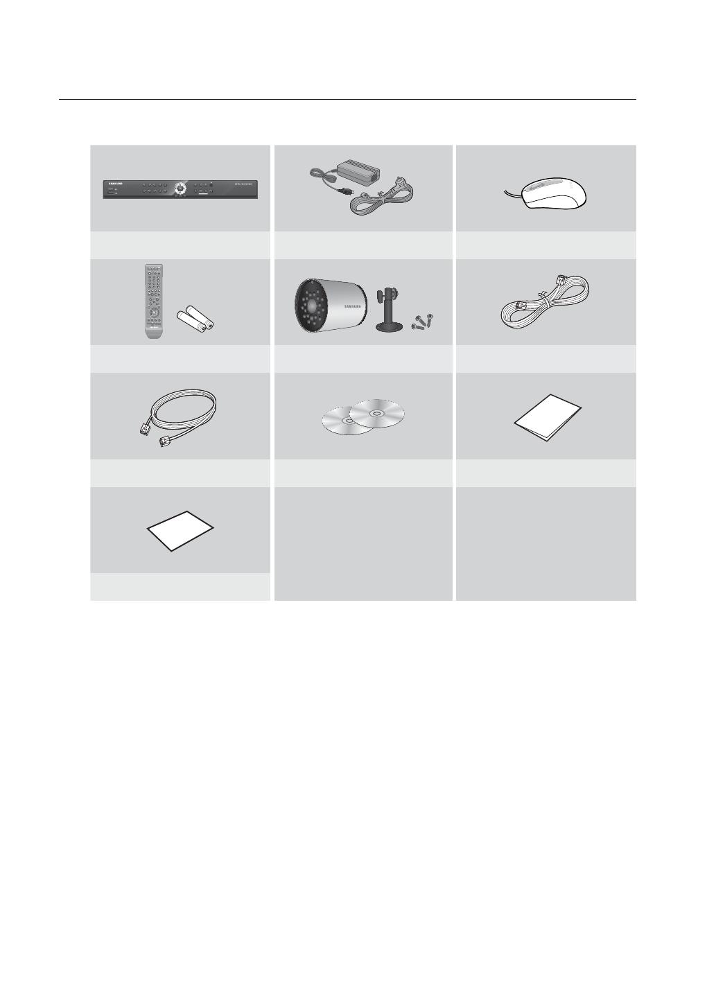
Package Contents
Please unwrap the product, and place the product on a flat place or in the place to be installed.
Please check the following contents are included in addition to the main unit.
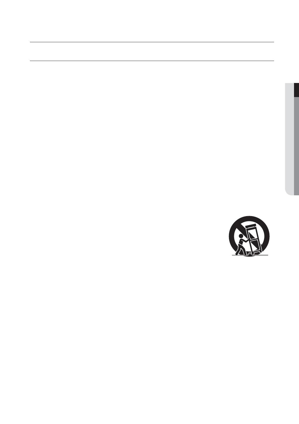
❖ SDE-4001N Package
1
6
2
7
3
8
4
9
!
REC
MENU
POWER
HDD
ALARM
+
/
SEARCH
@
MODE
PREV
NEXT
ALARM
5
0/10
+
DVR (1SET) Adapter (2EA) / Power Cable (2EA) Mouse (1EA)
Remote Control (1EA) / Battery (2EA) SED-1001R (2SET) SEB-1005R (4SET)
Camera Cable (6EA) Network Cable (1EA) SmartViewer (1EA) / Manual CD (1EA)
Quick Start Guide (1EA) Warranty Card (1EA)

10_ overview
overview
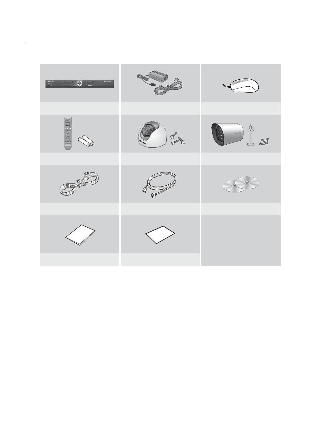
❖ SDE-4001P Package
1
6
2
7
3
8
4
9
!
REC
MENU
POWER
HDD
ALARM
+
/
SEARCH
@
MODE
PREV
NEXT
ALARM
5
0/10
+
DVR (1SET) Adapter (2EA) / Power Cable (2EA) Mouse (1EA)
Remote Control (1EA) / Battery (2EA) SED-1001R (2SET) SEB-1005R (2SET)
Camera Cable (4EA) Network Cable (1EA) SmartViewer (1EA) / Manual CD (1EA)
Quick Start Guide Warranty Card (1EA)
J
Depending on sales territory, quantity of Quick Start Guide differs.
SDE-4001P/AJ Model doesn’t include “Warranty Card”.
English _11
OVERVIEW
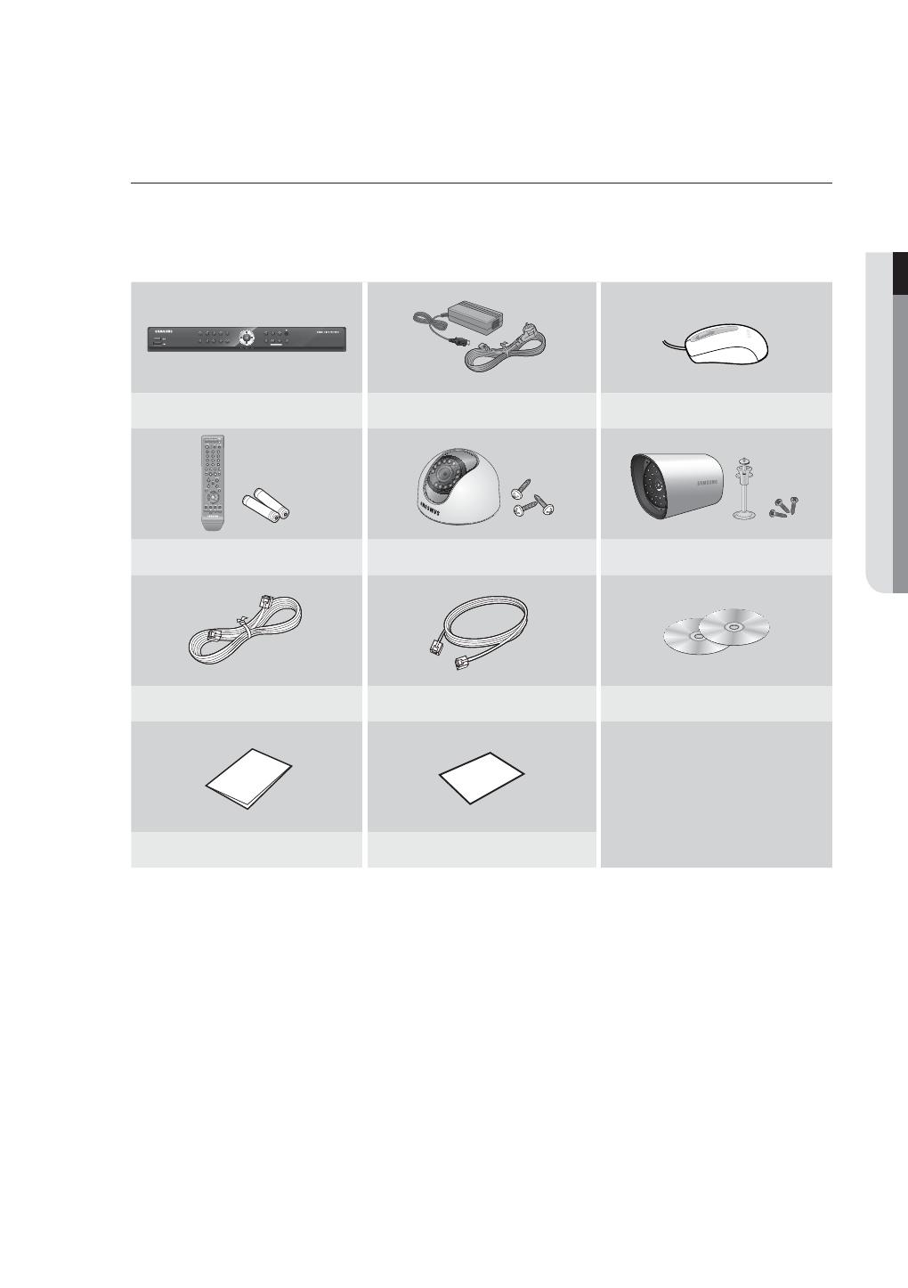
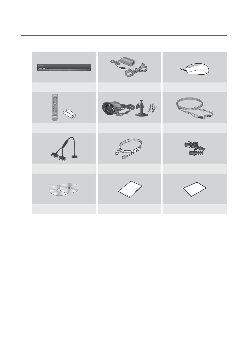
❖ SDE-4003N Package
DVR (1SET) Adapter (1EA) / Power Cable (1EA) Mouse (1EA)
Remote Control (1EA) / Battery (2EA) SEB-1020R (4SET) Camera Cable (4EA)
Camera Power Cable (1EA) Network Cable (1EA) Expansion pipe (12EA)
SmartViewer (1EA) / Manual CD (1EA) Quick Start Guide (1EA) Warranty Card (1EA)
12_ overview
overview
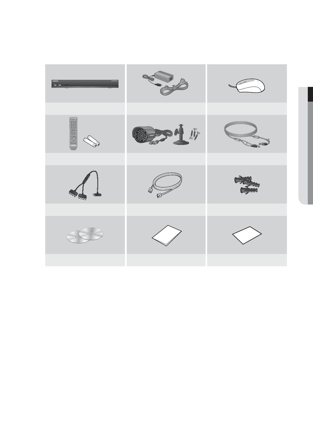
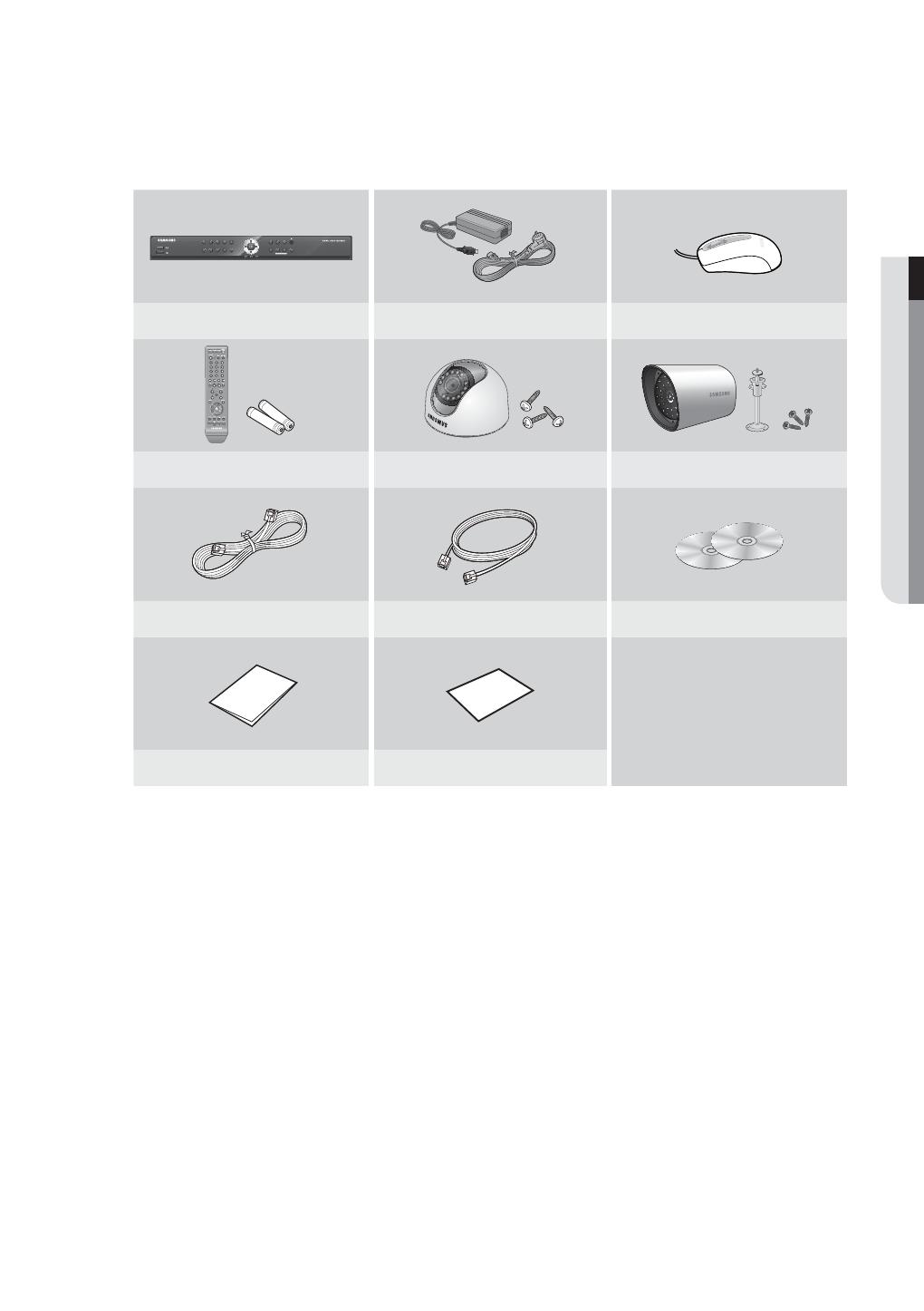
❖ SDE-4004N Package
1
6
2
7
3
8
4
9
!
REC
MENU
POWER
HDD
ALARM
+
/
SEARCH
@
MODE
PREV
NEXT
ALARM
5
0/10
+
DVR (1SET) Adapter (2EA) / Power Cable (2EA) Mouse (1EA)
Remote Control (1EA) / Battery (2EA) SEB-1007R (4SET) Camera Cable (4EA)
Network Cable (1EA) SmartViewer (1EA) / Manual CD (1EA) Quick Start Guide (1EA)
Warranty Card (1EA)

English _13
OVERVIEW
❖ SDE-4005N Package
1
6
2
7
3
8
4
9
!
REC
MENU
POWER
HDD
ALARM
+
/
SEARCH
@
MODE
PREV
NEXT
ALARM
5
0/10
+
DVR (1SET) Adapter (2EA) / Power Cable (2EA) Mouse (1EA)
Remote Control (1EA) / Battery (2EA) SEB-1005R (4SET) Camera Cable (4EA)
Network Cable (1EA) SmartViewer (1EA) / Manual CD (1EA) Quick Start Guide (1EA)
Warranty Card (1EA)
14_ overview
overview
❖ SDE-5001N Package
1
6
2
7
3
8
4
9
!
REC
MENU
POWER
HDD
ALARM
+
/
SEARCH
@
MODE
PREV
NEXT
ALARM
5
0/10
+
DVR (1SET) Adapter (2EA) / Power Cable (2EA) Mouse (1EA)
Remote Control (1EA) / Battery (2EA) SED-1001R (4SET) SEB-1005R (4SET)
Camera Cable (8EA) Network Cable (1EA) SmartViewer (1EA) / Manual CD (1EA)
Quick Start Guide (1EA) Warranty Card (1EA)
J
SDE-5001P/AJ Model doesn’t include “Warranty Card”.
English _15
OVERVIEW
❖ SDE-5002N Package
1
6
2
7
3
8
4
9
!
REC
MENU
POWER
HDD
ALARM
+
/
SEARCH
@
MODE
PREV
NEXT
ALARM
5
0/10
+
DVR (1SET) Adapter (2EA) / Power Cable (2EA) Mouse (1EA)
Remote Control (1EA) / Battery (2EA) SED-1001R (4SET) SEB-1007R (4SET)
Camera Cable (8EA) Network Cable (1EA) SmartViewer (1EA) / Manual CD (1EA)
Quick Start Guide (1EA) Warranty Card (1EA)
J
SDE-5002P/AJ Model doesn’t include “Warranty Card”.
16_ overview
overview
❖ SDE-5003N Package
DVR (1SET) Adapter (1EA) / Power Cable (1EA) Mouse (1EA)
Remote Control (1EA) / Battery (2EA) SEB-1020R (8SET) Camera Cable (8EA)
Camera Power Cable (1EA) Network Cable (1EA) Expansion pipe (24EA)
SmartViewer (1EA) / Manual CD (1EA) Quick Start Guide (1EA) Warranty Card (1EA)
English _17
OVERVIEW
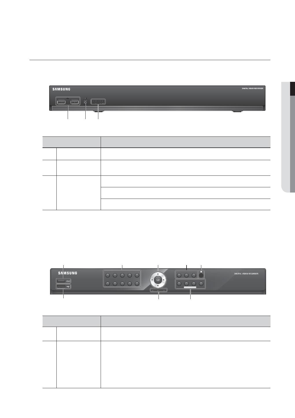
PART NAMES AND FUNCTIONS (FRONT)
SDE-4003/5003
Part Names Functions
USB Port Connects the USB devices.
b
Remote Control
Receiver
Input the remote control signal.
c
LED Indicator
POWER : Displays the power ON/OFF status.
ALARM : Lights on when an event occurs.
REC : Lights on when recording is in progress.
M
All functions of SDE-4003/5003 are operable with mouse control, since there are no front buttons.
SDE-4001/4002/4004/4005/5001/5002
Part Names Functions
Power Used to turn the DVR ON/OFF.
b
Channel
Used to select channel numbers directly in the Live Mode, or numbers in the numeric input
mode.
CHANNEL 1–9 : Press each button between 1 to 9. (8CH : 8)
CHANNEL 10 : Press the [0/10+] button fi rst, then press the [0/10+] within 1 second.
CHANNEL 11–16 : Press the [0/10+] button first, then press any number between 1 to 6
within 1 second.
cb
1
6
2
7
3
8
4
9
!
REC
MENU
POWER
HDD
ALARM
+
/
SEARCH
@
MODE
PREV
NEXT
ALARM
5
0/10
+
b c

18_ overview
overview
Part Names Functions
c
Direction (
◄►
) /
Select Button
Used to change a value or move the cursor up/down/left/right.
Selects a menu item or executes the selected menu.
REC Starts or ends the recording.
►
/
Play/Pause : Used to pause or resume the screen.
Stop : Used to stop the playback.
Remote Control
Receiver
Input the remote control signal.
MENU Either goes to the system menu screen or moves to the upper menu from the lower menu.
SEARCH / PREV
Starts search menu.
PREV : Used to move to the previous page in setup or search page.
MODE / NEXT
Each time you press the button in Live mode, the screen mode will be switched in sequence.
Each time you press the button in play mode, the screen mode will be switched in sequence.
(1 live channel + (N-1) live channel)
NEXT : Used to move to the next page in setup or search page.
ALARM
Cancels the ALARM LED and the audible alarm when the alarm is going off, and to remove the
icon.
LED Indicator
HDD : Displays the normal access to HDD.
Upon access to HDD, LED is on.
POWER : Displays the power ON/OFF status.
ALARM : Lights on when an event occurs.
USB Port Connects the USB devices.

English _19
OVERVIEW
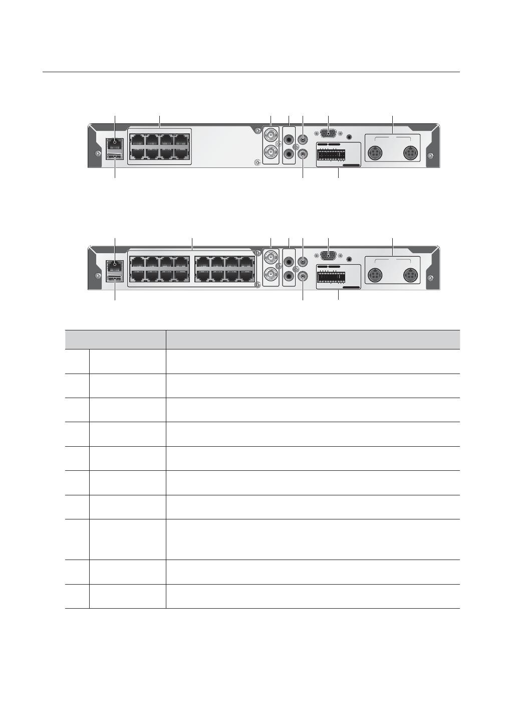
PART NAMES AND FUNCTIONS (REAR)
SDE-4003
SDE-5003
Part Names Functions
AUDIO IN Input ports (RCA jack) for the audio signal.
b
VIDEO IN Input port for the composite video signal.
c
SPOT BNC type of output port for the Spot signal.
VGA OUT Output port for VGA video signal.
DC 12V DVR power input port.
NETWORK NETWORK connector port.
VIDEO OUT BNC type of output port for the composite video signal.
AUDIO OUT Output port (RCA jack) for the audio signal.
M
[CONSOLE] is designed for the service repair purpose only.
SDE-4003 and SDE-5003 Model don’t support the function of “ALARM IN” and “ALARM OUT”.
SERIAL
1
ALARM
OUT
RS-
485
COM COM
2
1
2
3
4 5 6 7 8 G1 2
3
456 7 8 G
ALARM IN
NETWORK
CONSOLE
VGA OUT
SERIAL
VIDEO OUT
87654321
CH1 CH2
CH3 CH4
9 10111213141516
SPOT
AUDIO OUT
DC 12 V
AUDIO IN
VIDEO IN
VIDEO IN
NETWORK
CONSOLE
VGA OUT
VIDEO OUT
4321
CH1 CH2
CH3 CH4
5678
SPOT
AUDIO OUT
DC 12 V
AUDIO IN
VIDEO IN
VIDEO IN
b c
SERIAL
1
ALARM
OUT
RS-
485
COM COM
212 3 4 5 6 7 8
9
10 11 12
13 14
15 16
G
G
ALARM IN
NETWORK
CONSOLE
VGA OUT
VIDEO OUT
8764321
CH1 CH2
CH3 CH4
9 10111213141516
SPOT
AUDIO OUT
DC 12 V
AUDIO IN
VIDEO IN
VIDEO IN
5
b c
20_ overview
overview
SDE-4001/4002/4004/4005
SDE-5001/5002
Part Names Functions
NETWORK NETWORK connector port.
b
CAMERA IN Video Signal input ports (UTP type connector).
c
VIDEO IN Composite Video Signal Input Port (BNC type connector).
AUDIO IN Audio input signal port (RCA jack).
VIDEO OUT Video Signal Output Port (RCA jack).
VGA VGA Video Signal Output Port.
POWER Camera and DVR power input port.
ALARM
- ALARM IN 1~4 : Alarm Input port.
- ALARM OUT : Alarm Output port.
- SENSOR POWER : Sensor Power Output port.
AUDIO OUT Audio Signal Output Port (RCA jack).
USB USB connector port.
1 - 12 CH 13 - 16 CH
NETWORK
USB
AUDIO IN 1
AUDIO IN 2
VIDEO IN 2
VIDEO IN 1
VIDEO OUT
CONSOLE
CAMERA POWER
12V
12V
SENSOR POWER
G G G
COM
14321
DVR POWER
VGA
AUDIO OUT
5
1
6
2
7
3
8
4
ALARM IN ALARM OUT
b c
NETWORK
USB
AUDIO IN 1
AUDIO IN 2
VIDEO IN 2
VIDEO IN 1
VIDEO OUT
CONSOLE
CAMERA POWER
12V
12V
SENSOR POWER
G G G
COM
14321
DVR & CAMERA POWER
VGA
AUDIO OUT
1 - 12 CH 13 - 16 CH
5
1
6
2
7
3
8
4
13
9
14
10
15
11
16
12
ALARM IN ALARM OUT
b c
/