6 Plasma TV
Contents
After reading this manual, keep it handy for future reference.
Warning/Caution . . . . . . . . . . . . . . . . . . . . . . . . . . . . . . . .2
Digital Cable Compatibility . . . . . . . . . . . . . . . . . . . . . . . . .3
Safety Instructions . . . . . . . . . . . . . . . . . . . . . . . . . . . . .4~5
Introduction
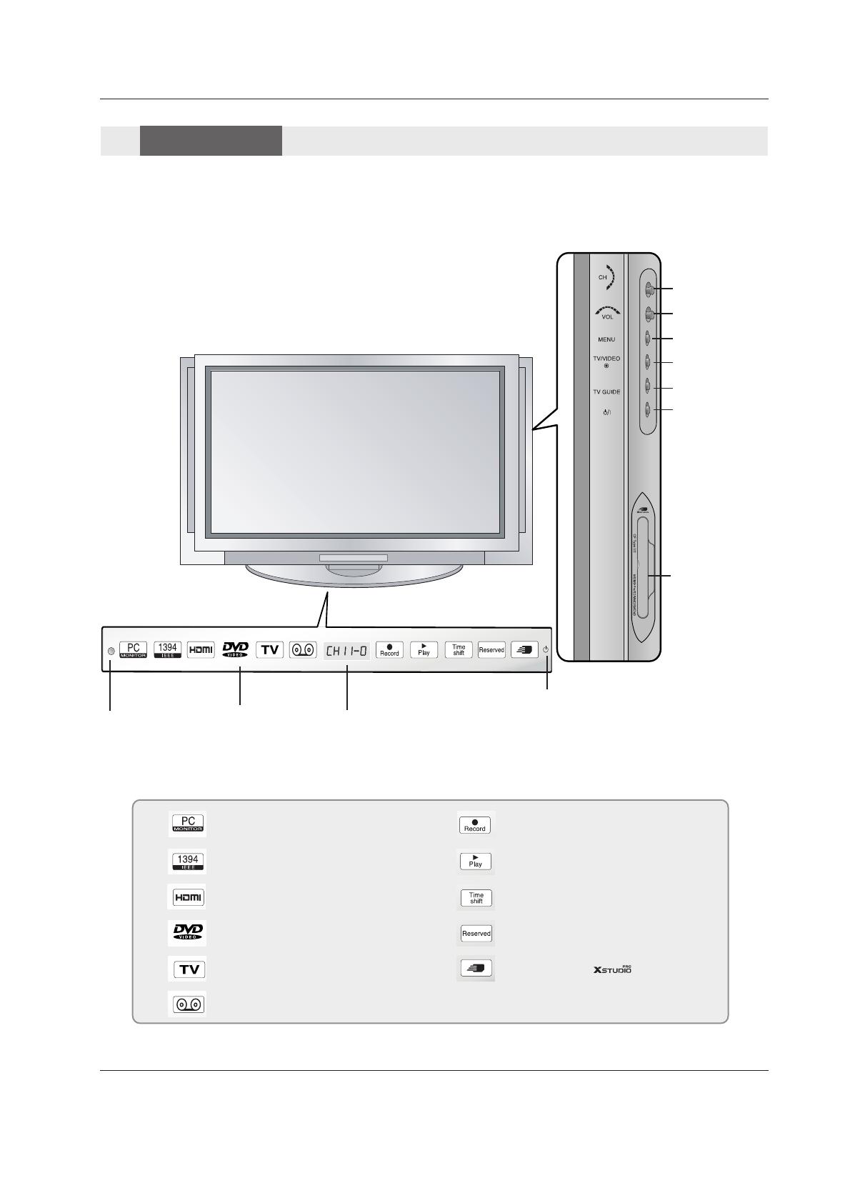
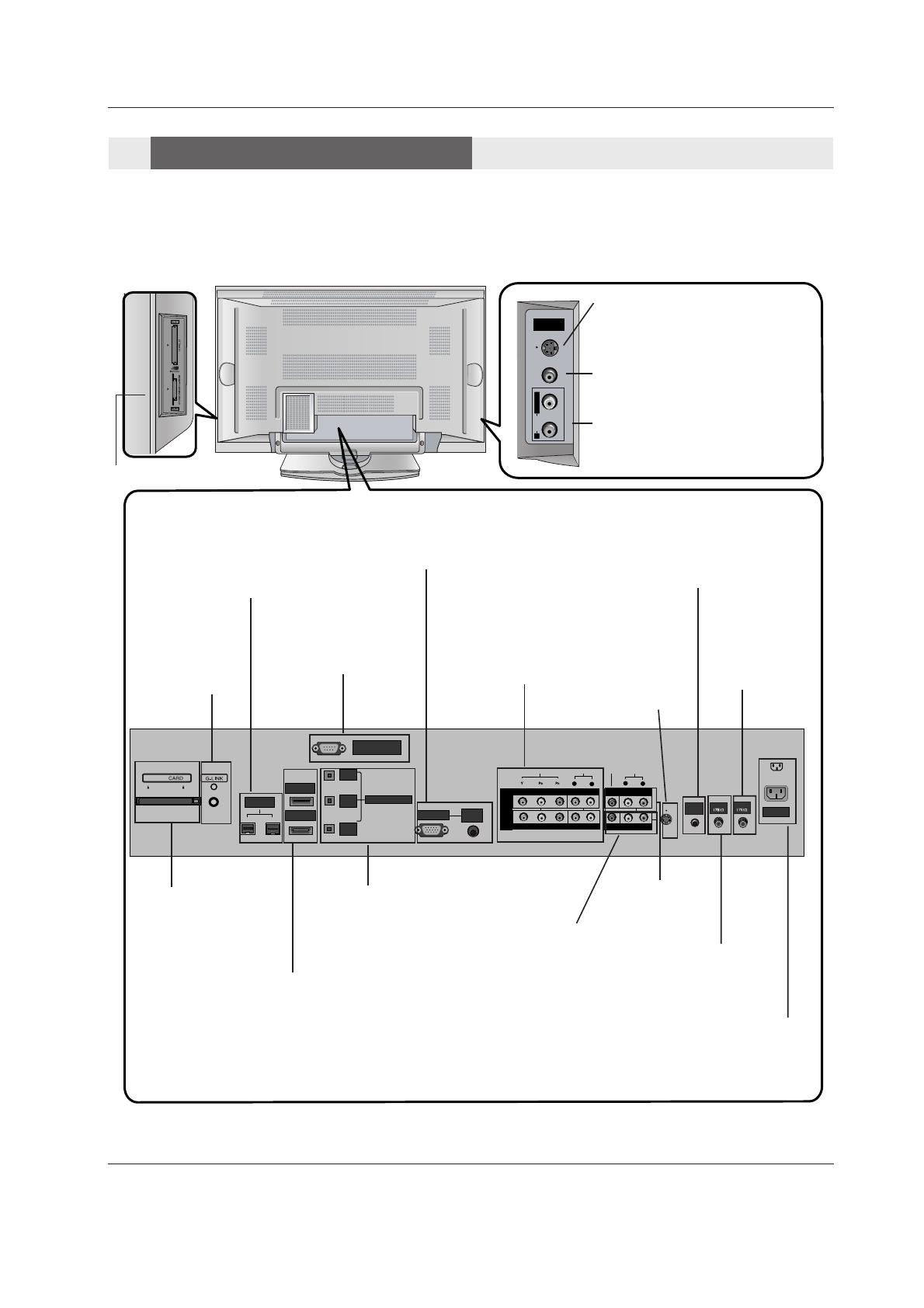
Controls/Connection Options . . . . . . . . . . . . .8~11
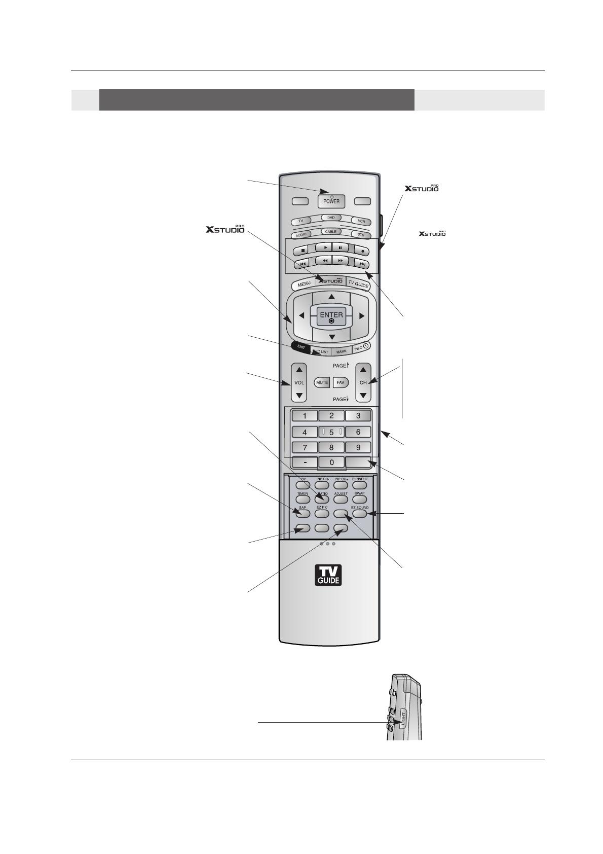
Remote Control Key Functions . . . . . . . . . . 12~13
Installation
Accessories . . . . . . . . . . . . . . . . . . . . . . . . . . .14
Installation Instructions
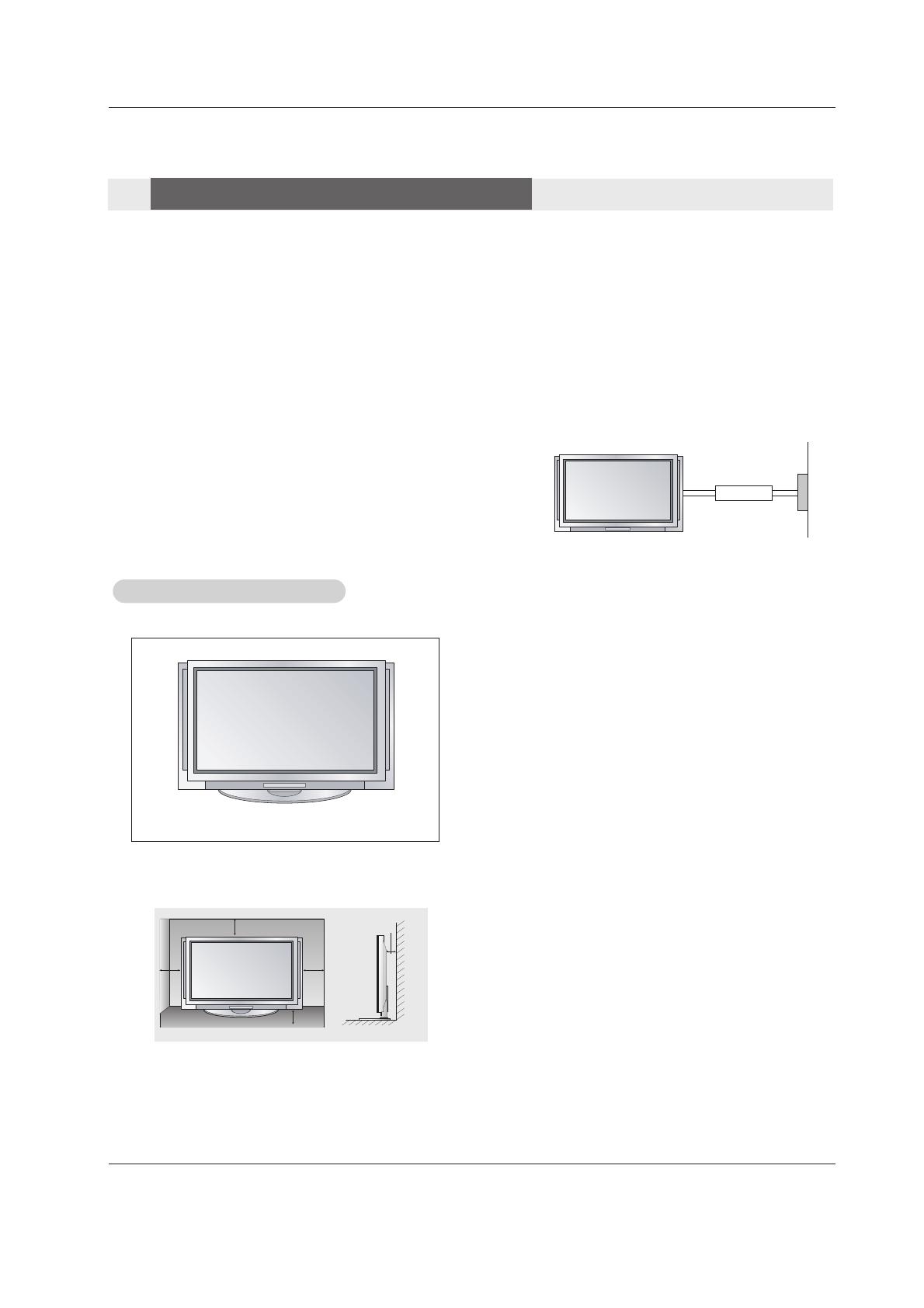
Joining the TV assembly to the wall to protect the set tum-
bling . . . . . . . . . . . . . . . . . . . . . . . . . . . . . . . . .14
Install the RING SPACER with the bolts on the set
as shown . . . . . . . . . . . . . . . . . . . . . . . . . . . . .15
Remove or Attache the Plate Cover . . . . . . . . . . .17
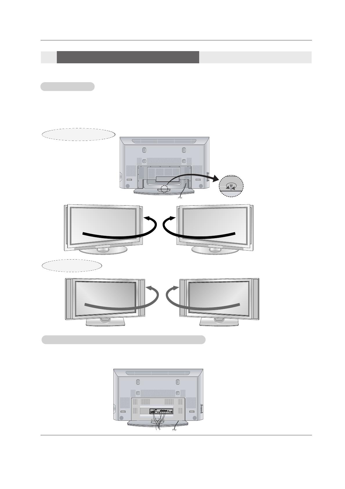
Swivel function . . . . . . . . . . . . . . . . . . . . . . . . .18
Arrangement wires . . . . . . . . . . . . . . . . . . . . . .18
External Equipment Connections . . . . . . . . . .19~25
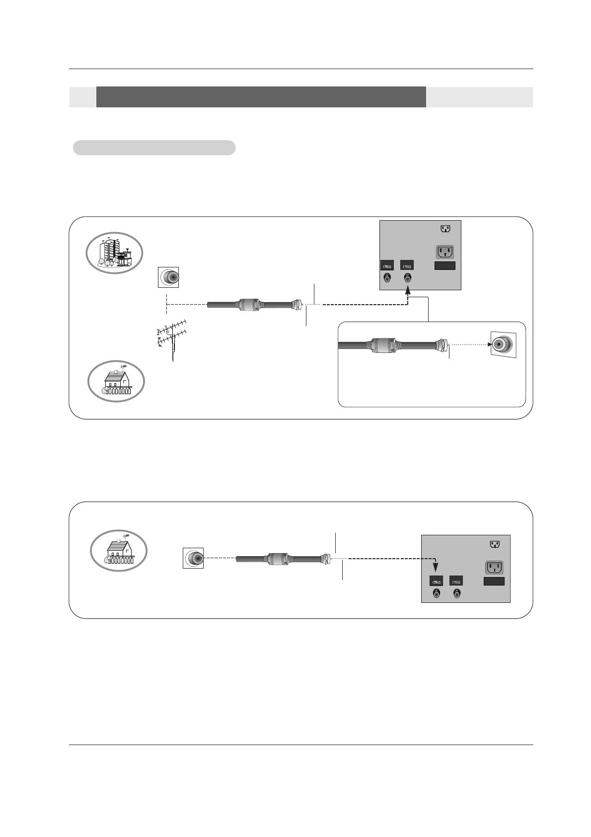
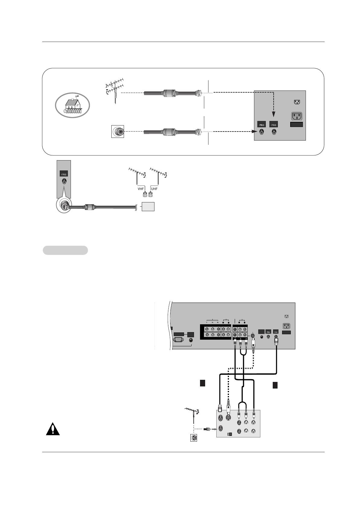
Antenna or Cable Connection . . . . . . . . . . .19~20
VCR Setup . . . . . . . . . . . . . . . . . . . . . . . . . . .20
External A/V Source Setup . . . . . . . . . . . . . . . .21
DVD Setup . . . . . . . . . . . . . . . . . . . . . . . . . . . .21
CableCARD
TM
Setup . . . . . . . . . . . . . . . . . . . . .22
HDSTB Setup . . . . . . . . . . . . . . . . . . . . . . . . .22
PC Setup . . . . . . . . . . . . . . . . . . . . . . . . . .23~24
Monitor Out Setup . . . . . . . . . . . . . . . . . . . . . .25
Digital Audio Output . . . . . . . . . . . . . . . . . . . . .25
HDMI . . . . . . . . . . . . . . . . . . . . . . . . . . . . . . .26~28
TV Guide On Screen Setup . . . . . . . . . . . . . .29~35
Operation
Turning the TV On . . . . . . . . . . . . . . . . . . . . . . . .36
HOME Menu . . . . . . . . . . . . . . . . . . . . . . . . . . . .37
TV Setup . . . . . . . . . . . . . . . . . . . . . . . . . . . .38~56
On-screen Menus Language Selection . . . . . . .38
Setup Menu Options
EZ Scan (Channel Search) . . . . . . . . . . . . . . . .39
Manual Scan . . . . . . . . . . . . . . . . . . . . . . . . . .39
Channel Edit . . . . . . . . . . . . . . . . . . . . . . . . . . .40
DTV Signal Strength . . . . . . . . . . . . . . . . . . . . .40
Channel Label Setup . . . . . . . . . . . . . . . . . . . .41
Main Picture Source Selection . . . . . . . . . . . . .41
Input Label . . . . . . . . . . . . . . . . . . . . . . . . . . . .41
Video Menu Options
EZ Picture . . . . . . . . . . . . . . . . . . . . . . . . . . . .42
Manual Picture Control (Custom Option) . . . . . .42
Color Temperature Control . . . . . . . . . . . . . . . .42
Video Reset . . . . . . . . . . . . . . . . . . . . . . . . . . .42
Audio Menu Options
Audio Language . . . . . . . . . . . . . . . . . . . . . . . .43
EZ SoundRite / EZ Sound . . . . . . . . . . . . . . . . .43
Manual Sound Control (custom Option) . . . . . . .44
Front Surround . . . . . . . . . . . . . . . . . . . . . . . . .44
TV Speakers On/Off Setup . . . . . . . . . . . . . . . .45
Stereo/SAP Broadcasts Setup . . . . . . . . . . . . .45
BBE . . . . . . . . . . . . . . . . . . . . . . . . . . . . . . . . .45
Time Menu Options
Auto Clock Setup . . . . . . . . . . . . . . . . . . . . . . .46
Manual Clock Setup . . . . . . . . . . . . . . . . . . . . .46
On/Off Timer Setup . . . . . . . . . . . . . . . . . . . . .46
Sleep Timer / Auto Off . . . . . . . . . . . . . . . . . . . .47
Option Menu Features
Advanced . . . . . . . . . . . . . . . . . . . . . . . . . . . . .48
Cinema 3:2 Mode Setup . . . . . . . . . . . . . . . .48
Low Power . . . . . . . . . . . . . . . . . . . . . . . . . .48
LG Logo . . . . . . . . . . . . . . . . . . . . . . . . . . . .49
Aspect Ratio Control . . . . . . . . . . . . . . . . . . . . .50
Caption . . . . . . . . . . . . . . . . . . . . . . . . . . . . . . .51
Caption / Text . . . . . . . . . . . . . . . . . . . . . . . . . .51
Caption Option . . . . . . . . . . . . . . . . . . . . . . . .52
ISM Method . . . . . . . . . . . . . . . . . . . . . . . . . . .53
Front Display . . . . . . . . . . . . . . . . . . . . . . . . . .53
Auto Demo . . . . . . . . . . . . . . . . . . . . . . . . . . . .54
Lock Menu Options
Parental Lock Setup . . . . . . . . . . . . . . . . . . . . .56
CableCARD
TM
Function
Cable menu options . . . . . . . . . . . . . . . . . . . . .57
Scrambled channel . . . . . . . . . . . . . . . . . . . . . .57
Cable Channel List . . . . . . . . . . . . . . . . . . . . . .58
Emergency Alert Message . . . . . . . . . . . . . . . .58
Recorded TV . . . . . . . . . . . . . . . . . . . . . . .59~63
Notes on Memory Card . . . . . . . . . . . . . . . .64~67
Photo List . . . . . . . . . . . . . . . . . . . . . . . . . .68~69
Music List . . . . . . . . . . . . . . . . . . . . . . . . . .70~72
Timeshift . . . . . . . . . . . . . . . . . . . . . . . . . . .73~74
Recording . . . . . . . . . . . . . . . . . . . . . . . . . .75~77
TV Guide On Screen
TM
System . . . . . . . . . . .78~98
IEEE 1394 . . . . . . . . . . . . . . . . . . . . . . . . . .99~110
Remote Control
PIP (Picture-in-Picture)/POP/Twin Picture
Watching PIP/POP/Twin Picture . . . . . . . . . . ..111
Selecting an Input Signal Source for PIP/Twin Picture
.111
Swapping PIP/Twin Picture . . . . . . . . . . . . . . .111
TV Program Selection for PIP . . . . . . . . . . . . .111
Moving the PIP sub picture . . . . . . . . . . . . . . .112
Adjusting Main and Sub Picture Sizes for Twin Picture .112
POP (Picture-out-of-Picture: Channel Scan) . .112
APM. . . . . . . . . . . . . . . . . . . . . . . . . . . . . . . .113
Bried Info. . . . . . . . . . . . . . . . . . . . . . . . . . . . .114
EZ Mute . . . . . . . . . . . . . . . . . . . . . . . . . . . . .115
Screen Setup for PC mode . . . . . . . . . . . . . . .116
External Control Device Setup . . . . . . . . . . . . . .117~122
IR Codes . . . . . . . . . . . . . . . . . . . . . . . . . . . . . .123~124
Programming the Remote . . . . . . . . . . . . . . . . . . . . .125
Programming Codes . . . . . . . . . . . . . . . . . . . . .126~127
Troubleshooting Checklist . . . . . . . . . . . . . . . . . . . . .128
Maintenance . . . . . . . . . . . . . . . . . . . . . . . . . . . . . . . .129
Product Specifications . . . . . . . . . . . . . . . . . . . . . . . .130
Warranty . . . . . . . . . . . . . . . . . . . . . . . . . . . . . . .131~132
Contents
Contents