Page is loading ...

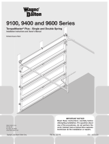
TorqueMaster
®
Plus - Single and Double Spring
Installation Instructions and Owner’s Manual
6100 Windload
IMPORTANT NOTICE!
Read these instructions carefully before
attempting installation. If in question about
any of the procedures, do not perform the
work. Instead, have a trained door systems
technician do the installation or repairs.
Copyright 2009 Wayne-Dalton Corp. Part No. 341780 REV1 08/03/2009
Wayne-Dalton Corp.
P.O. Box 67
Mt. Hope, OH 44660
www.wayne-dalton.com

2
Please Do Not Return This Product To The Store. Contact your local Wayne-Dalton dealer. To find your local Wayne-Dalton dealer, refer to your
local yellow pages/business listings or go to the Find a Dealer section online at www.wayne-dalton.com
Definition of key words used in this manual:
INDICATES A POTENTIALLY HAZARDOUS
SITUATION WHICH, IF NOT AVOIDED, COULD
RESULT IN SEVERE OR FATAL INJURY.
CAUTION: PROPERTY DAMAGE OR INJURY CAN RESULT
FROM FAILURE TO FOLLOW INSTRUCTIONS.
IMPORTANT: REQUIRED STEP FOR SAFE AND PROPER
DOOR OPERATION.
NOTE: Information assuring proper installation of the door.
Table of Contents
Important Safety Instructions .................................................. 2
Package Contents ................................................................... 3
Door Section Identification ...................................................... 4
Tools Required ........................................................................ 5
Removing an Existing Door ..................................................... 5
Preparing the Opening ........................................................... 6
Installation ........................................................................7-28
Optional Installations ...................................................... 29-33
TorqueMaster
®
Plus Rest Instructions .........29-31
Side Lock ............................................................. 32
Pull Rope .............................................................. 32
Trolley Operator .................................................... 33
Maintenance ................................................................... 34-35
Cleaning ............................................................... 34
Painting Instructions ........................................34-35
Dealer Locator Information.................................................... 35
Warranty ............................................................................... 36
WARNING
WARNING
TO AVOID POSSIBLE
INJURY, READ THESE INSTRUCTIONS
CAREFULLY BEFORE ATTEMPTING
INSTALLATION. IF IN QUESTION ABOUT
ANY OF THE PROCEDURES, DO NOT
PERFORM THE WORK. INSTEAD, HAVE A
TRAINED DOOR SYSTEMS TECHNICIAN
DO THE INSTALLATION OR REPAIRS.
1. READ AND FOLLOW ALL INSTALLATION INSTRUCTIONS.
2. Wear protective gloves during installation to avoid possible
cuts from sharp metal edges.
3. It is always recommended to wear eye protection when using
tools, otherwise eye injury could result.
4. Avoid installing your new door on windy days. Door could fall
during the installation causing severe or fatal injury.
5. Doors 12’- 0” wide and wider should be installed by two
persons, to avoid possible injury.
6. Operate door ONLY when it is properly adjusted and free from
obstructions.
7. If a door becomes hard to operate, inoperative or is damaged,
immediately have necessary adjustments and/or repairs made
by a trained door system technician using proper tools and
instructions.
8. DO NOT stand or walk under a moving door, or permit
anybody to stand or walk under an electrically operated door.
9. DO NOT place fingers or hands into open section joints when
closing a door. Use lift handles/gripping points when operating
door manually.
10. DO NOT permit children to operate garage door or door
controls. Severe or fatal injury could result, should the child
become entrapped between the door and the floor.
11. Due to constant extreme spring tension, DO NOT attempt any
adjustment, repair or alteration to any part of the door,
especially to springs, spring brackets, bottom corner brackets,
red colored fasteners, cables or supports. To avoid possible
severe or fatal injury, have any such work performed
by a trained door systems technician using proper tools and
instructions.
12. On electrically operated doors, pull down ropes must be
removed and locks must be removed or made inoperative in
the open (unlocked) position.
13. Top section of door may need to be reinforced when attaching
an electric opener. Check door and/or opener manufacturer’s
instructions.
14. VISUALLY inspect door and hardware monthly for worn and or
broken parts. Check to ensure door operates freely.
15. Test electric opener’s safety features monthly, following
opener manufacturer’s instructions.
16. NEVER hang tools, bicycles, hoses, clothing or anything else
from horizontal tracks. Track systems are not intended or
designed to support extra weight.
After installation is complete, fasten this manual
near garage door.

3
Please Do Not Return This Product To The Store. Contact your local Wayne-Dalton dealer. To find your local Wayne-Dalton dealer, refer to your
local yellow pages/business listings or go to the Find a Dealer section online at www.wayne-dalton.com
Package Contents
(1)TORQUEMASTER
®
SPRING TUBE
1/4”-14 X 5/8” SELF TAPPING
SCREWS (AS REQUIRED)
1/4”-20 X 11/16” SELF DRILLING
SCREWS (AS REQUIRED)
DOOR SECTIONS (AS REQUIRED)
(2) 3/8”-16 X 3/4”
TRUSS HEAD BOLTS
(1) CENTER BRACKET
ASSEMBLY
(2) VERTICAL
TRACKS RH/LH
(2) FULLY ADJUSTABLE RH/LH
FLAGANGLES (AS REQUIRED)
5/16” X 1 5/8” LAG SCREWS
(AS REQUIRED)
WEATHER SEAL & NAILS
(IF INCLUDED)
1/4”- 20 FLANGED HEX
NUTS (AS REQUIRED)
DRUM WRAPS
(1) RIGHT & (1) LEFT
PULL ROPE
(IF INCLUDED)
(2) QUICK INSTALL RH/LH
FLAGANGLES (AS REQUIRED)
(1) LOOSE WINDING SHAFT
(SINGLE SPRING ONLY)
5/16” X 18 X 3/4”
CARRIAGE BOLTS
(AS REQUIRED)
(2) 5/16”HEX NUTS
CABLE DRUM ASSEMBLIES
(1) RIGHT & (1) LEFT
(2) HORIZONTAL TRACKS RH/LH
NOTE: DEPENDING ON THE DOOR MODEL, SOME PARTS LISTED WILL NOT BE SUPPLIED IF NOT
NECESSARY. REAR SUPPORTS MAY NOT BE INCLUDED WITH YOUR DOOR.
ROLLERS
(AS REQUIRED)
(2) HORIZONTAL ANGLES
(21-15/16” OR 80”)
(AS REQUIRED)
U-BARS
(AS REQUIRED)
Q.I. JAMB BRACKETS
(AS REQUIRED)
(2) 3/8”- 16 HEX NUTS
END BRACKETS
(1) RIGHT & (1) LEFT
WARNING
Rachet Bracket is under
EXTREME SPRING TENSION.
To avoid possible severe or
fatal injury, DO NOT remove
fasteners from ratchet bracket
until spring(s) are fully
wnwound.
To safely unwind spring(s) read
and follow the directions in the
installation instructions/owners
manual.
DO NOT REMOVE THIS TAG.
P/N 300547
5/16”X 1-1/4” CLEVIS
PIN & COTTER PIN
STUDPLATE
(IF INCLUDED)
OPERATOR BRACKET
LIFT HANDLES
PULL HANDLES
#10 X 5/8” PAN HEAD SELF
TAPPING SCREWS (BLACK
PAINTED HEADS)
PRE-INSTALLATION
1/4” - 20 X 9/16”
TRACK BOLTS
ROLLER SLIDE
(AS REQUIRED)
(2) TOP ROLLER SLIDE
JBUS JAMB BRACKETS
(AS REQUIRED)
1/4”-14 X 7/8” SELF
DRILLING SCREWS
WINDLOAD LABEL
1/4”-20 X 5/8”
CARRIAGE BOLTS
1/4”-14 X 5/8” SELF
DRILLING SCREWS

Tools Needed:
4
Please Do Not Return This Product To The Store. Contact your local Wayne-Dalton dealer. To find your local Wayne-Dalton dealer, refer to your
local yellow pages/business listings or go to the Find a Dealer section online at www.wayne-dalton.com
Door Section Identification
TOP SECTION
INTERMEDIATE SECTION
LOCK SECTION
BOTTOM SECTION
BOTTOM BRACKET
WARNING LABELS
ASTRAGAL
WARNING LABEL
WARNING LABELS
Hinges are always pre-attached at the
top of each section (except top section).
The BOTTOM SECTION can be identified
by the factory attached bottom astragal,
and by the bottom bracket warning labels
on each end stile.
The LOCK SECTION can be identified by
having no labels attached.
The INTERMEDIATE SECTION can be
identified by having warning labels
attached to the right and left end stile.
The TOP SECTION can be identified with
no pre-installed end or center hinges and
the warning label attached in the upper
middle of the section.

5
Please Do Not Return This Product To The Store. Contact your local Wayne-Dalton dealer. To find your local Wayne-Dalton dealer, refer to your
local yellow pages/business listings or go to the Find a Dealer section online at www.wayne-dalton.com
Tools Required
POWER DRILL RATCHET WRENCH PLIERS/WIRE CUTTERS
PHILLIPS HEAD SCREWDRIVER PENCIL
1/8”, 3/16” DRILL BITS
FLAT TIP SCREWDRIVER
7/16” SOCKET DRIVER
TAPE MEASURE
NEEDLE NOSE PLIERS
7/16”, 1/2”, 9/16”, 5/8”
SOCKETS
3/8”, 7/16”, 1/2”, 9/16”
WRENCHES
SAFETY GLASSES
STEP LADDER
PRE-INSTALLATION
VICE GRIPS VICE CLAMPS
GLOVES
(2) SAW HORSES
HAMMER
Removing An Existing Door
IMPORTANT: COUNTERBALANCE SPRING TENSION MUST ALWAYS BE RELEASED BEFORE ANY ATTEMPT IS MADE TO START REMOVING
AN EXISTING DOOR.
A POWERFUL SPRING RELEASING ITS ENERGY SUDDENLY CAN CAUSE SEVERE OR FATAL INJURY. TO AVOID INJURY
HAVE A TRAINED DOOR SYSTEMS TECHNICIAN, USING PROPER TOOLS AND INSTRUCTIONS, RELEASE THE SPRING
TENSION.
For detailed information see supplemental instructions “Removing an Existing Door /Preparing the Opening”. These instructions are available
at no charge from Wayne-Dalton Corp., P.O. Box 67, Mt. Hope, OH 44660, or at www.wayne-dalton.com.
WARNING

Tools Needed:
6
Please Do Not Return This Product To The Store. Contact your local Wayne-Dalton dealer. To find your local Wayne-Dalton dealer, refer to your
local yellow pages/business listings or go to the Find a Dealer section online at www.wayne-dalton.com
HEADROOM REQUIREMENT
Preparing the Opening
TRACK TYPE TorqueMaster
®
15” Radius track 12-1/2” (318 mm)
12” Radius track 11” (279 mm)
DOOR HEIGHT TRACK
MANUAL
LIFT
MOTOR
OPERATED
7’0” 12”, 15” Radius
98”
(2489 mm)
125”
(3048 mm)
8’0” 12”, 15” Radius
110”
(2794 mm)
137”
(3353 mm)
WEATHER SEAL
BACKROOM REQUIREMENT
HEADROOM
BACKROOM
DOOR
WIDTH
DOOR
HEIGHT
LEVEL HEADER
PLUMB JAMBS
HEADER BOARD
2” X 6” LUMBER
PREFERRED
SUITABLE MOUNTING
SURFACE 2” X 6”
LUMBER MINIMUM
P5
Recommended
tools from
page 5
HEADER
JAMB
JAMB
QUICK INSTALL TRACK
JAMB
WEATHER
SEAL
WARNING
FAILURE TO SECURELY
ATTACH A SUITABLE
MOUNTING PAD TO STRUCTURALLY SOUND
FRAMING COULD CAUSE SPRINGS TO VIOLENTLY
PULL MOUNTING PAD FROM WALL, RESULTING
IN SEVERE OR FATAL INJURY.
If you just removed your existing door or you are installing a new
door, complete all steps in PREPARING THE OPENING.
To ensure secure mounting of track brackets, side and center
brackets, or steel angles to new or retro-fit construction, it is
recommended to follow the procedures outlined in DASMA
Technical Data Sheets #156, #161 and #164 at www.dasma.
com.
The inside perimeter of your garage door opening should be
framed with wood jamb and header material. The jambs and
header must be securely fastened to sound framing members. It
is recommended that 2” x 6” lumber be used. The jambs must be
plumb and the header level. The jambs should extend a minimum
of 12” (305 mm) above the top of the opening for TorqueMaster
®
counterbalance systems. For low headroom applications, the
jambs should extend to the ceiling height. Minimum side clearance
required, from the opening to the wall, is 3-1/2” (89 mm).
IMPORTANT: CLOSELY INSPECT JAMBS, HEADER AND MOUNTING
SURFACE. ANY WOOD FOUND NOT TO BE SOUND, MUST BE
REPLACED.
For TorqueMaster
®
counterbalance systems, a suitable mounting
surface (2” x 6”) must be firmly attached to the wall, above the
header at the center of the opening.
NOTE: Drill a 3/16” pilot hole in the mounting surface to avoid
splitting the lumber. Do not attach the mounting surface with
nails.
Weather Seal (May Not Be Included):
Cut the weather seal if necessary to fit the header and jambs.
For quick install track: Align the header seal with the inside
edge of the header and temporarily secure it to the header with
equally spaced nails. Next, fit the jamb seals up tight against
the header seal and flush with the inside edge of the jamb.
Temporarily secure the jamb seals with equally spaced nails.
This will keep the bottom section from falling out of the opening
during installation. Space nails approximately 12” apart.
For fully adjustable track: Align the header seal 1/8” to 1/4”
inside the header and temporarily secure it to the header with
equally spaced nails. Next, fit the jamb seals up tight against the
header seal and 1/8” to 1/4” inside the jamb. Temporarily secure
the jamb seals with equally space nails approximately 12” to 18”
apart. This will keep the bottom section from falling out of the
opening during installation.
NOTE: Do not permanently attach weather seal to the jamb at this
time.
HEADROOM REQUIREMENT: Headroom is defined as the space
needed above the top of the door for tracks, springs, etc. to allow
the door to open properly. If the door is to be motor operated,
2-1/2” (64 mm) of additional headroom is required.
BACKROOM REQUIREMENT: Backroom is defined as the
distance needed from the opening back into the garage to allow
the door to open fully.

7
Tools Needed:
Please Do Not Return This Product To The Store. Contact your local Wayne-Dalton dealer. To find your local Wayne-Dalton dealer, refer to your
local yellow pages/business listings or go to the Find a Dealer section online at www.wayne-dalton.com
None
Attaching Quick Install Flag
Angles to Vertical Tracks
NOTE: If you have fully adjustable
flagangles, skip this step and complete
Step 2.
Place the lower quick install tab of the
flagangle in the quick install feature of
the vertical track. Give the flagangle 1/4
turn to lock in place. Repeat for other
side.
NOTE: After completing this step,
continue with Step 3.
QUICK INSTALL TAB UNLOCKED QUICK INSTALL TAB LOCKED
FLAGANGLE
VERTICAL
TRACK
1
LEFT HAND TRACK AND FLAGANGLE
RIGHT HAND TRACK AND FLAGANGLE
FLAGANGLE
VERTICAL
TRACK
INSTALLATION
Installation
Begin the installation of the door by checking the opening. It must be the same size as the door. Vertical jambs must be plumb with
header. Side clearance, from edge of door to wall, must be a minimum of 3-1/2” (89mm) on each side.
IMPORTANT: STAINLESS STEEL OR PT 2000 COATED LAG SCREWS MUST BE USED WHEN INSTALLING CENTER BEARING BRACKETS,
END BRACKETS, JAMB BRACKETS, OPERATOR MOUNTING/SUPPORT BRACKETS AND DISCONNECT BRACKETS ON TREATED LUMBER
(PRESERVATIVE-TREATED). STAINLESS STEEL OR PT 2000 COATED LAG SCREWS ARE NOT NECESSARY WHEN INSTALLING PRODUCTS
ON UNTREATED LUMBER.
NOTE: It is recommended that 5/16” lag screws be pilot drilled using a 3/16” drill bit prior to fastening.

Tools Needed:
8
Tools Needed:
Please Do Not Return This Product To The Store. Contact your local Wayne-Dalton dealer. To find your local Wayne-Dalton dealer, refer to your
local yellow pages/business listings or go to the Find a Dealer section online at www.wayne-dalton.com
Position the horizontal angle as shown.
Place tabs of horizontal angle in the key
slot of horizontal track. Using a hammer,
tap the horizontal angle towards the
curved end of the track until the hole in
track and angle are aligned. Set tracks
aside.
NOTE: For larger doors, a full length
horizontal angle may be spot welded
to the horizontal track. If the horizontal
angle is not welded, the horizontal angle
must be installed as shown.
Horizontal Angles
Hammer
HORIZONTAL
TRACK
HORIZONTAL
ANGLE
HORIZONTAL ANGLE
HORIZONTAL TRACK
HOLE
HOLE
TABS
KEY SLOT
3
HORIZONTAL
TRACK
TABS
HORIZONTAL
TRACK
HORIZONTAL
ANGLE
Attaching Fully Adjustable
Flagangles to Vertical Track
None
2
NOTE: If quick install flagangles were
installed in Step 1, skip this step and
continue with Step 3. If not, complete
this step.
If you have quick install vertical track,
hand tighten the flagangle to the
vertical track using (1) stud plate and
(2) 1/4” - 20 flange hex nuts. Repeat for
other side.
Secure the flange nuts after flagangle
spacing is complete (Step 15).
If you have fully adjustable vertical
track, hand tighten the flagangle to the
vertical track using (2) 1/4”- 20 x 9/16”
track bolts and (2) 1/4”- 20 flange hex
nuts. Repeat for other side.
Secure the flange nuts after flagangle
spacing is complete (Step 15).
1/4”- 20
FLANGE HEX
NUTS
FULLY ADJUSTABLE
FLAGANGLE
STUD
PLATE
QUICK INSTALL
VERTICAL TRACK
QUICK INSTALL TRACK
(2) 1/4”- 20 X 9/16”
TRACK BOLTS
1/4”- 20
FLANGE HEX
NUTS
FULLY ADJUSTABLE
FLAGANGLE
FULLY ADJUSTABLE
VERTICAL TRACK
FULLY ADJUSTABLE TRACK

Tools Needed:
9
Please Do Not Return This Product To The Store. Contact your local Wayne-Dalton dealer. To find your local Wayne-Dalton dealer, refer to your
local yellow pages/business listings or go to the Find a Dealer section online at www.wayne-dalton.com
Installing The Jamb Brackets
NOTE: The following (JBUS) denotes a
slotted jamb bracket.
NOTE: The following (QI) denotes a
quick install jamb bracket. No additional
hardware is needed.
Measure the length of the vertical
track. Using the jamb bracket schedule,
determine the placement of the jamb
brackets for your door height and track
type.
To install the (QI) jamb brackets:
Align the twistlock tab on (QI) jamb
bracket with the quick install feature
in the track and turn the jamb bracket
perpendicular to the track so the
mounting flange is toward the back leg
of the track.
To install the (JBUS) jamb brackets:
Loosely fasten the (JBUS) jamb bracket
to the track with a 1/4”-20 x 9/16”
track bolt and nut.
None
(JBUS) JAMB BRACKET
1/4”-20 X 9/16”
TRACK BOLT
1/4”-20
FLANGED HEX
NUT
4
LEFT SIDE SHOWN
RIGHT SIDE SHOWN
TWISTLOCK
TABS
TOP
HOLE
BOTTOM
HOLE
MIDDLE
HOLE
QUICK INSTALL FEATURE
(Q.I.) JAMB BRACKET INSTALLATION
(JBUS) JAMB BRACKET SCHEDULE
DOOR HEIGHT NO. OF
SECTIONS
NO. OF JAMB
BRACKETS
(EACH JAMB)
LOCATION OF CENTER LINE OF JAMB BRACKETS
MEASURED FROM BOTTOM OF TRACK
(ALL DIMENSIONS ± 2”)
WINDLOAD SPECIFICATION 0228
7’-0” or Less 4 1 2”, 63”
7’-1’’ to 8’-0” 4 or 5 1 2”, 34”
WINDLOAD SPECIFICATION 0229, 0600, 0602, & 0606
7’-0” or Less 4 2 25-1/2”, 63”
7’-1’’ to 8’-0” 4 or 5 2 23”, 34”
WINDLOAD SPECIFICATION 0235, 0236, 0237, 0604, & 0609
7-0” or Less 4 3 2”, 25-1/2”, 63”
7’-1” to 8’-0” 4 or 5 3 2”, 23”, 34”
WINDLOAD SPECIFICATION 0230, 0232, 0233, 0234, 0601, 0603, 0605, 0607, & 0608
7’-0” or Less 4 4 2”, 25-1/2”, 34”, 63”
7’-1’’ to 8’-0” 4 or 5 5 2”, 23”, 34”, 58”, 75”
INSTALLATION
JAMB BRACKET SCHEDULE
DOOR
HEIGHT
1ST SET 2ND SET 3RD SET
JAMB BKT POSITION JAMB BKT POSITION JAMB BKT POSITION
7’0”
76” Track (1930 mm)
QIJB - 5 BOTTOM QIJB - 7 BOTTOM NOT APPLICABLE
8’0”
88” Track (2235 mm)
QIJB - 6 TOP QIJB - 7 BOTTOM QIJB - 9 TOP
3RD SET HOLES
2ND SET HOLES
1ST SET HOLES

Tools Needed:
10
Please Do Not Return This Product To The Store. Contact your local Wayne-Dalton dealer. To find your local Wayne-Dalton dealer, refer to your
local yellow pages/business listings or go to the Find a Dealer section online at www.wayne-dalton.com
(2) 1/4”-14 X 5/8” SELF DRILLING SCREWS
NOTE: Double car door struts are color
coded. 18 gauge (.046) have red ends. 20
gauge (.034) have blue ends.
Bottom Section:
1. If your doors windload option code
begins with 06, place the U-Bar with the
notched ends over the bottom rib of the
bottom section, notches facing down.
Center U-Bar left to right on section.
If your doors windload option code begins
with 02, place the U-Bar with the notched
ends over the bottom rib of the bottom
section, notches facing down. The end
of the U-bar will fit between the bottom
bracket flange and the bottom section rib.
Center U-Bar left to right on section.
2. Fasten the U-Bar at each end through
the top flange with (1) 1/4”-14 x 7/8”
self drilling screw. If your doors windload
option code begins with 02, also fasten
the U-bar at each end to the bottom
section rib with (2) 1/4”-14 X 5/8” self
drilling screws, through the two holes in
the bottom bracket flange.
3. Place (2) 1/4”-14 x 5/8” self tapping
screws through each pre-punched hole at
each intermediate hinge location.
4. Place the U-Bar over the top rib of
the bottom section with the eight pre-
punched holes, facing up. Center U-Bar
left to right on section. Attach the U-Bar
at each end through the bottom flange
with (1) 1/4”-14 x 7/8” self drilling screw.
5. Finish securing the U-Bars to the
section, by placing (2) 1/4” -14 x 5/8”
self tapping screws midway between the
end of the door and intermediate hinge
locations and (1) 1/4” -14 x 5/8” self
tapping screw approximately eight inches
from each end.
Intermediate/ Top Section(s):
1. Place the U-Bar over the top rib of each
of the remaining sections with the (8)
pre-punched holes at the ends, facing up.
Center U-Bar left to right on section.
2. Fasten the U-Bar(s) at each end
through the top and bottom flange with (2)
1/4”-14 x 7/8” self drilling screws.
3. Place (2) 1/4”-14 x 5/8” self tapping
screws through each intermediate hinge.
4. Finish securing the U-Bar(s) to the
section, by placing (2) 1/4” -14 x 5/8”
self tapping screws midway between the
end of the door and intermediate hinge
locations and (1) 1/4” -14 x 5/8” self
tapping screw approximately eight inches
from each end.
Attaching U-Bars
1/4”-14 X 5/8” SELF
TAPPING SCREWS
U-BAR
NOTCHED U-BAR
1/4”-14 X 5/8”
SELF TAPPING SCREWS
1/4”-14 X 7/8”
SELF DRILLING
SCREWS
U-BAR
Power Drill
7/16” Socket
Driver
Saw Horses
5
BOTTOM SECTION
INTERMEDIATE SECTION
INTERMEDIATE SCREW
PLACEMENT
INTERMEDIATE SCREW
PLACEMENT
1/4”-14 X 5/8” SELF
TAPPING SCREWS
1/4”-14 X 7/8” SELF DRILLING
SCREWS
FOR OPTION CODES STARTING WITH 02
FLANGE
U-BAR
RIB
FOR OPTION CODES STARTING WITH 06

Tools Needed:
11
Please Do Not Return This Product To The Store. Contact your local Wayne-Dalton dealer. To find your local Wayne-Dalton dealer, refer to your
local yellow pages/business listings or go to the Find a Dealer section online at www.wayne-dalton.com
INSTALLATION
PULL HANDLE PLACEMENT REFERENCE ON DOUBLE WIDE DOORS
6
Tape Measure
Pencil
Power Drill
1/16” Drill Bit
Pull Handle Installation
BOTTOM
SECTION
LOCATE THE CENTER
(2) #10 X 5/8”
PAN HEAD
SELF TAPPING
SCREWS
PULL HANDLE
BOTTOM
SECTION
PULL HANDLE PLACEMENT REFERENCE ON SINGLE WIDE DOORS
On single doors, locate and mark the
horizontal and vertical center on the
bottom rail of the bottom section.
Center the pull handle using the vertical
and horizontal lines as reference on the
bottom section rail as shown. Using the
pull handle as a template, mark the two
holes in the pull handle on the horizontal
line of the bottom section rail. Drill a
1/16” pilot hole, then fasten pull handles
using (2) #10 X 5/8” pan head self
tapping screws.
NOTE: Reference illustrations for pull
handle positions on single and double
car garage doors. If your door came with
two pull handles they must be installed
as shown in the bottom illustration.
8” MAX.
BOTTOM OF THE DOOR

Tools Needed:
12
Please Do Not Return This Product To The Store. Contact your local Wayne-Dalton dealer. To find your local Wayne-Dalton dealer, refer to your
local yellow pages/business listings or go to the Find a Dealer section online at www.wayne-dalton.com
7
Tape Measure
Pencil
Power Drill
1/16” Drill Bit
Lift Handle Installation
NOTE: Reference illustrations for lift
handle positions on single and double
car garage doors.
Measure the width of the center stile
which will receive the lift handle(s).
Divide that measurement in half and
mark a vertical line on the center of the
stile.
If you are installing two lift handles on
the stile, you will need to measure from
the edge of the center stile to the center
line mark. Divide that measurement
in half and draw a second and third
vertical line parallel to the previously
made center line mark.
Measure the height of the panel. Divide
that measurement in half and mark a
horizontal line, intersecting the vertical
line(s) previously marked. Measure up
3-7/8” from the intersecting line(s) and
mark another horizontal line.
Use the point(s) where the top
horizontal line intersects the vertical
line(s) to locate the top hole of the lift
handle(s).
Using the lift handle as a template,
mark this location on the stile. Keeping
the carriage handle aligned on the
vertical line, mark the lower carriage
handle hole on the stile.
Drill 1/16” pilot holes, then fasten both
lift handles using #10 X 5/8” pan head
self tapping screws.
If the door came with two sets of lift
handles repeat process.
LIFT HANDLE PLACEMENT REFERENCE ON SINGLE WIDE DOORS
LIFT HANDLE PLACEMENT REFERENCE ON DOUBLE WIDE DOORS
LOCK SECTION
CENTER STILE
LOCATE THE
CENTER
3-7/8”
LOCATE THE
CENTERS
LIFT HANDLES
HORIZONTAL
LINE
#10 X 5/8” PAN
HEAD SELF
TAPPING SCREWS
VERTICALLY
ALIGNED
VERTICALLY ALIGNED
SINGLE WIDE DOORS
DOUBLE WIDE DOORS

13
Tools Needed:
Tools Needed:
Please Do Not Return This Product To The Store. Contact your local Wayne-Dalton dealer. To find your local Wayne-Dalton dealer, refer to your
local yellow pages/business listings or go to the Find a Dealer section online at www.wayne-dalton.com
Drums
Warning
Warning
Power Drill
7/16” Socket
Driver
TORQUEMASTER
®
DRUM
BOTTOM SECTION
MILFORD PIN
ROLLERS
ROLLER SLIDE
BOTTOM BRACKET
BOTTOM
SECTION
ASTRAGAL
Roller Slides
Starting with the bottom section, place
a roller slide on the top left side of the
U-Bar and align with the first set of
holes (closest to the section) as shown.
Attach the roller slide to the U-Bar with
(2) 1/4”-14 x 5/8” self tapping screws.
Repeat for opposite side. Install roller
slides on the right and left side of each
U-bar, on all remaining sections with
the exception of the top section.
A viewing hole on the roller slide will
allow for correct positioning of roller
slide on U-bars. Place roller slides on
the sections as follows:
Lock Section (second section) use the
second set of holes.
Intermediate Section (Third section) use
the third set of holes.
Fasten all roller slides to the U-bar with
(2) 1/4”-14 x 5/8” self tapping screws.
None
ROLLER SLIDE
1/4”-14 X 5/8” SELF
TAPPING SCREWS
1
2
3
4
U-BAR
8
9
1
2
3
4
VIEWING HOLE
WARNING LABEL
WARNING LABEL
IMPORTANT: RIGHT AND LEFT HAND IS
ALWAYS DETERMINED FROM INSIDE THE
BUILDING LOOKING OUT.
NOTE: For door section identification see
page 4.
TorqueMaster
®
counterbalance drums
are marked right and left hand. Uncoil
the counterbalance cables and make
sure you place the right hand cable loop
on the right hand milford pin and place
the left hand cable loop on the left hand
milford pin. Insert a roller into bottom
bracket of the bottom section and insert
another roller in the roller slide at the top
of the bottom section. Repeat for other
side.
NOTE: Verify astragal (bottom seal)
is aligned with door section. If there
is more than 1/2” excess astragal on
either side, trim astragal even with door
section.
INSTALLATION

Tools Needed:
14
Tools Needed:
Please Do Not Return This Product To The Store. Contact your local Wayne-Dalton dealer. To find your local Wayne-Dalton dealer, refer to your
local yellow pages/business listings or go to the Find a Dealer section online at www.wayne-dalton.com
Vertical Track
IMPORTANT: THE TOPS OF THE
VERTICAL TRACKS MUST BE LEVEL
FROM SIDE TO SIDE. IF THE BOTTOM
SECTION WAS SHIMMED TO LEVEL IT.
THE VERTICAL TRACK ON THE SHIMMED
SIDE, MUST BE RAISED THE HEIGHT OF
THE SHIM.
Position the left hand vertical track
assembly over the rollers of the bottom
section. Make sure the counterbalance
cable is located between the rollers
and the door jamb. Drill 3/16” pilot
holes into the jambs for the lag
screws. Loosely fasten jamb brackets
and flagangle to the jamb using
5/16” x 1-5/8” lag screws. Tighten lag
screw securing bottom jamb bracket to
jamb, to maintain 5/8” spacing. Hang
cable drum over flagangle.
Repeat for the right hand side.
3/16” Drill Bit
Power Drill
7/16” Socket
Driver
Tape Measure
Level
Step Ladder
11
BOTTOM SECTION
VERTICAL TRACK
ROLLER
5/8”
15R QI FLAGANGLE
12R QI FLAGANGLE
12R & 15R FULLY
ADJUSTABLE FLAGANGLE
LAG
SCREW
LOCATIONS
LAG
SCREW
LOCATIONS
LAG
SCREW
LOCATIONS
LAG
SCREW
QUICK INSTALL
JAMB BRACKET
Bottom Section
Center the bottom section in the door
opening. Level section using wooden
shims (if necessary) under the bottom
section.
Level
10
BOTTOM SECTION
WEATHER SEAL
LEVEL
WOOD SHIMS
(IF NECESSARY)
BOTTOM
SECTION
5/16” X
1-5/8” LAG
SCREWS
FLAGANGLE
VERTICAL
TRACK
ASSEMBLY
Q.I. JAMB
BRACKET
JBUS JAMB
BRACKET

15
Tools Needed:
Tools Needed:
Please Do Not Return This Product To The Store. Contact your local Wayne-Dalton dealer. To find your local Wayne-Dalton dealer, refer to your
local yellow pages/business listings or go to the Find a Dealer section online at www.wayne-dalton.com
Stacking Sections
Power Drill
7/16” Socket
Driver
(2) 1/4”-14 X 5/8”
SELF TAPPING SCREWS
END HINGES (LEFT HAND SHOWN, RIGHT
HINGE SYMMETRICALLY OPPOSITE)
INTERMEDIATE HINGES
(3) 1/4”-14 X 5/8” SELF
TAPPING SCREWS
12
NOTE: For door section identification see
page 4.
NOTE: Make sure hinges are flipped down,
when stacking another section on top.
NOTE: Larger doors will use long shaft
rollers with double wide end hinges
Place rollers in hinge tubes of the second
section (lock section). With assistance, lift
second section and guide rollers into the
vertical tracks. Keep patterns on front of
sections aligned, and fasten center hinges
first and end hinges last with 1/4”-14 x
5/8” self tapping screws. Repeat for other
section(s) except top section.
IMPORTANT: PUSH & HOLD THE HINGE
LEAF AGAINST SECTION WHILE SECURING
WITH 1/4”-14 X 5/8” SELF TAPPING
SCREWS. END HINGES HAVE (2) SCREWS
AND INTERMEDIATE HINGES HAVE (3)
SCREWS; DOUBLE END HINGES HAVE (5)
SCREWS.
NOTE: Lock(s) are required if door is not
installed with opener. Install lock at this
time (sold separately) see instructions in
OPTIONAL INSTALLATION on page 32.
(5) 1/4”-14 X 5/8” SELF
TAPPING SCREWS
DOUBLE END HINGES (LEFT HAND SHOWN,
RIGHT HINGE SYMMETRICALLY OPPOSITE)
13
Top Roller Slides
To install the top roller slides, align
the slots in the top roller slide with the
second set of holes on the bottom of the
U-bar.
Loosely, fasten using (2) 1/4” - 14 x 5/8”
self tapping screws. The bracket will be
tightened and adjusted in Step 18. Insert
rollers into top roller slide. Repeat for
left side.
TOP ROLLER SLIDE
1ST
2ND
3RD
TOP RIGHT SIDE
(2) 1/4”- 14 X 5/8”
SELF TAPPING
SCREWS
ROLLER
Power Drill
7/16” Socket
Driver
Step Ladder
INSTALLATION

Tools Needed:
16
Please Do Not Return This Product To The Store. Contact your local Wayne-Dalton dealer. To find your local Wayne-Dalton dealer, refer to your
local yellow pages/business listings or go to the Find a Dealer section online at www.wayne-dalton.com
14
Power Drill
7/16” Socket
Driver
7/16” Wrench
IMPORTANT! WHEN CONNECTING A
TROLLEY TYPE GARAGE DOOR OPENER
TO THIS DOOR, A WAYNE-DALTON
OPENER/TROLLEY BRACKET MUST BE
SECURELY ATTACHED TO THE TOP SEC-
TION OF THE DOOR, ALONG WITH ANY
U-BARS PROVIDED WITH THE DOOR. THE
INSTALLATION OF THE OPENER MUST
BE ACCORDING TO MANUFACTURER’S
INSTRUCTIONS AND FORCE SETTINGS
MUST BE ADJUSTED PROPERLY.
Place the top half of the operator
bracket inside the bottom half and hold
flush against the inside of the top sec-
tion (as shown). Adjust the top / bottom
halves out against the U-bar and bottom
rib; loosely secure both halves together
with (4) 1/4” - 20 x 5/8” carriage bolts
and nuts.
NOTE: Install the track bolts as far apart
as possible (as shown), when fastening
the top / bottom halves together.
NOTE: For retro fit applications, the
adjustable operator bracket must be
aligned with the existing operator.
Locate the center of the top section and
align the center of both end tabs of the
adjustable operator bracket with the
sections center line; align the adjustable
operator bracket vertically.
To attach the adjustable operator
bracket:
Attach the operator bracket to the U-bar
with (2) 1/4” - 20 x 11/16” self drilling
screws and the bottom rib with
(2) 1/4” -14 x 5/8” self tapping screws
(as shown).
Now tighten all (4) previously installed
carriage bolts and nuts.
Adjustable Operator
Bracket Installation
ALIGN CENTER OF BOTH
END TABS WITH CENTER
LINE OF TOP SECTION
CENTER LINE OF TOP
SECTION
ADJUSTABLE OPERATOR
BRACKET
(TOP HALF)
ADJUSTABLE OPERATOR
BRACKET
(BOTTOM HALF)
TOP SECTION
BOTTOM RIB
U-BAR
TIGHTEN ALL (4)
CARRIAGE BOLTS
AND NUTS
(2) 1/4” -14 X 5/8”
SELF TAPPING
SCREWS
(4) 1/4” -20 X 5/8”
CARRIAGE BOLTS
AND NUTS
TYPICAL OPERATOR
ARM ATTACHMENT
BOTTOM RIB
U-BAR
(2) 1/4” -20 X 11/16”
SELF DRILLING SCREWS

Tools Needed:
17
Please Do Not Return This Product To The Store. Contact your local Wayne-Dalton dealer. To find your local Wayne-Dalton dealer, refer to your
local yellow pages/business listings or go to the Find a Dealer section online at www.wayne-dalton.com
Top Section
15
Hammer
Step Ladder
NAIL
TOP SECTION
Place the top section in the opening.
Temporarily secure the top section by
driving a nail in the header near the
center of the door and bending it over
the top section.
Now, flip up hinge leafs, hold tight
against section, and fasten center
hinges first, and end hinges last. (Refer
to Step 12).
Position flagangle between 1-11/16”
(43 mm) to 1-3/4” (44 mm) from the
edge of the door; tighten the bottom
lag screw. Flagangles must be parallel
to the door sections. Repeat for
opposite side.
IMPORTANT: THE DIMENSION
BETWEEN THE FLAGANGLES MUST BE
DOOR WIDTH PLUS 3-3/8” (86MM) TO
3-1/2” (89 MM) FOR SMOOTH, SAFE
DOOR OPERATION.
Complete the vertical track installation
by securing the center jamb bracket(s)
and tightening the other lag screws.
Repeat for opposite side.
DOOR WIDTH
+ 3-3/8” TO 3-1/2”
INSTALLATION
1-11/16” TO 1-3/4”
FLAGANGLE
TOP
SECTION

Tools Needed:
18
Please Do Not Return This Product To The Store. Contact your local Wayne-Dalton dealer. To find your local Wayne-Dalton dealer, refer to your
local yellow pages/business listings or go to the Find a Dealer section online at www.wayne-dalton.com
NOTE: If you have fully adjustable
flagangles, skip this step and complete
Step 17.
To install horizontal track, place the
curved end over the top roller. Align
key slot of the horizontal track with the
quick install tab of the flagangle. Push
curved portion of horizontal track down
to lock in place.
DO NOT RAISE DOOR UNTIL
HORIZONTAL TRACKS ARE
SE CURED AT REAR, AS OUTLINED
IN STEP 28, OR DOOR COULD
FALL FROM OVERHEAD POSI-
TION CAUSING SEVERE OR FATAL
INJURY.
Level the horizontal track assembly and
bolt the horizontal angle to the slot in
the flagangle using (1) 3/8” - 16 x 3/4”
truss head bolt and (1) 3/8” - 16 hex
nut. Repeat for other side. Remove the
nail that was temporarily holding the
top section in place, installed in Step
15.
IMPORTANT: FAILURE TO REMOVE NAIL
BEFORE ATTEMPTING TO RAISE DOOR
COULD CAUSE PERMANENT DAMAGE
TO TOP SECTION.
NOTE: If an idrive
®
opener will be
installed, position horizontal tracks
slightly above level.
NOTE: After completing this step,
continue with Step 18.
KEY
SLOT
QUICK
INSTALL
TAB
HORIZONTAL
TRACK
VERTICAL
TRACK
FLAGANGLE
16
WARNING
9/16” Socket
Ratchet Wrench
9/16” Wrench
Level
Step Ladder
KEY SLOT
QUICK
INSTALL
TAB
HORIZONTAL
TRACK
VERTICAL
TRACK
FLAGANGLE
Attaching Quick Install Flagangles
to Horizontal Tracks
3/8” - 16 X 3/4”
TRUSS HEAD BOLT
3/8” - 16 HEX NUT
HORIZONTAL TRACK
HORIZONTAL ANGLE

Tools Needed:
19
Please Do Not Return This Product To The Store. Contact your local Wayne-Dalton dealer. To find your local Wayne-Dalton dealer, refer to your
local yellow pages/business listings or go to the Find a Dealer section online at www.wayne-dalton.com
17
7/16” Socket
9/16” Socket
Ratchet Wrench
9/16” Wrench
Level
Step Ladder
NOTE: If quick install flagangles were
installed in Step 16, skip this step and
continue with Step 18. If not, complete
this step.
To install horizontal track, place the
curved end over the top roller. Align
the bottom of the horizontal track with
the vertical track. If you have quick
install horizontal track, hand tighten the
horizontal track to the flagangle with
a studplate and (2) 1/4”-20 flange
hex nuts. If you have fully adjustable
horizontal track, hand tighten the
horizontal track to the flagangle with
(2) 1/4” - 20 x 9/16” track bolts and (2)
1/4”-20 flange hex nuts.
DO NOT RAISE DOOR UNTIL
HORIZONTAL TRACKS ARE
SE CURED AT REAR, AS OUTLINED
IN STEP 28, OR DOOR COULD
FALL FROM OVERHEAD POSI-
TION CAUSING SEVERE OR FATAL
INJURY.
Level the horizontal track assembly and
bolt the horizontal angle to the slot in
the flagangle using (1) 3/8”-16 x 3/4”
truss head bolt and (1) 3/8”-16 hex nut.
Repeat for other side.
Remove the nail that was temporarily
holding the top section in place, installed
in Step 15.
IMPORTANT: FAILURE TO REMOVE NAIL
BEFORE ATTEMPTING TO RAISE DOOR
COULD CAUSE PERMANENT DAMAGE TO
TOP SECTION.
NOTE: If an idrive
®
opener will be
installed, position horizontal tracks
slightly above level.
WARNING
Attaching Adjustable Flagangles
to Horizontal Tracks
3/8” - 16 X 3/4”
TRUSS HEAD BOLT
3/8” - 16 HEX NUT
HORIZONTAL TRACK
HORIZONTAL ANGLE
INSTALLATION
1/4”-20 FLANGE
HEX NUTS
FLAGANGLE
STUDPLATE
QUICK INSTALL
HORIZONTAL TRACK
1/4”-20 FLANGE
HEX NUTS
FLAGANGLE
FULLY ADJUSTABLE
HORIZONTAL TRACK
1/4”-20 X 9/16”
TRACK BOLTS
QUICK INSTALL TRACK FULLY ADJUSTABLE TRACK

Tools Needed:
20
Tools Needed:
Please Do Not Return This Product To The Store. Contact your local Wayne-Dalton dealer. To find your local Wayne-Dalton dealer, refer to your
local yellow pages/business listings or go to the Find a Dealer section online at www.wayne-dalton.com
TorqueMaster
®
Spring Tube
TorqueMaster
®
springs come lubricated
and pre-assembled inside the
TorqueMaster
®
spring tube.
To install, lay the TorqueMaster
®
spring
tube on the floor (inside garage) in front
of the door with the labeled end to the
left.
LABELED END
TORQUEMASTER
®
SPRING TUBE
None
19
18
Adjusting Top Roller Slide
With horizontal tracks installed, you can
now adjust the top roller slide.
Vertically align the top section of the
door with the lower sections. Once
aligned, position the top roller,
out against the horizontal track, while
keeping the roller slide parallel with the
section.
Maintaining the slide’s position,
tighten the (2) 1/4” - 14 x 5/8” self
tapping screws.
TOP ROLLER
SLIDE
Power Drill
7/16” Socket
Driver
Step Ladder
TOP SECTION
1/4”-14 X 5/8” SELF
TAPPING SCREWS
CORRECT INCORRECT
TOP SECTION
/