Page is loading ...

Supplemental Setup and Operating
Instructions and Illustrated Parts Lists
for Ferris Zero-Turn Riding Mowers Using
Propane Fuel
5404081
Rev U
Briggs & Stratton Power Products Group, LLC.
5375 N. Main Street
Munnsville, NY 13409-4003
Model Description
5900690 IS3100ZBVP3261, Zero-Turn Riding Mower w/ Propane Fuel
5900691 IS3100ZBVP32, Zero-Turn Riding Mower w/ Propane Fuel
5900789 IS3100ZBVP3261, Zero-Turn Riding Mower w/ Propane Fuel & 16cc Pumps
5900790 IS3100ZBVP32, Zero-Turn Riding Mower w/ Propane Fuel & 16cc Pumps
5900942 IS3100ZBVP3261HT, Zero-Turn Riding Mower w/ Propane Fuel & 16cc Pumps
Not for
Reproduction

ES GB
Spanish English
Table of Contents
Operator Safety .................................................. 1
Propane Mower Operating Procedures ...................1
Propane Fuel Tank Filling Procedures ....................1
Procedures for Safe Handling of Propane ...............1
Features & Controls ........................................... 2
Control Functions ....................................................2
Operation ............................................................ 4
Checks Before Starting ...........................................4
Starting the Engine ..................................................4
Stopping the Rider ..................................................4
Regular Maintenance ......................................... 4
Removing the Propane Tanks .................................4
Re-installing the Propane Tanks .............................5
Initial Fill of a New Propane Tank ............................5
Excess Flow Valve ..................................................5
Leak Testing the Fuel System .................................6
Specifications ..................................................... 7
Seguridad del Operador .................................... 9
Funciones y Controles .................................... 10
Operación .......................................................... 12
Mantenimiento Regular ................................... 13
Especificaciones .............................................. 15
Illustrated Parts Lists....................................... 16
Tank Mount Group ................................................16
Instrument Control Panel Group ............................18
Fuel Supply Group ................................................20
Electrical Schematics
Charging Circuit ....................................................24
Cranking Circuit .....................................................25
Ignition Grounding Circuit / Operator
Presence ...............................................................26
PTO Clutch Circuit ................................................27
NOTE: In this manual, “left” and “right” are referred to as
seen from the operating position.
This manual is intended to supplement the operator’s manual included
with your machine. There is very important safety, operational and maintenance
information in this manual. Read and understand all information in your
operator’s manual and this supplement manual before attempting to operate this
machine. Save these original instructions for future reference.
Briggs & Stratton Power Products Group, LLC.
Copyright © 2012 Briggs & Stratton Corporation
Milwaukee, WI, USA. All rights reserved.
FERRIS is a trademark of Briggs & Stratton Corporation
Milwaukee, WI, USA.
Contact Information:
Briggs & Stratton Power Products Group, LLC.
5375 N. Main St.
Munnsville, NY 13409-4003
(800) 933-6175
www.ferrisindustries.com
Not for
Reproduction

1
GB
Operator Safety
Operator Safety
WARNING
Avoid serious injury or death from operating
a mower using propane fuel. Follow mower
operating procedures, propane fuel and
propane fuel tank filling producedures.
PROPANE FUEL TANK FILLING
PROCEDURES
• A propane fuel tank is a cylinder designed to
contain a liquefied petroleum gas (propane)
under pressure that is highly flammable. Filling,
operating and servicing of this cylinder (tank)
must be conducted at an approved propane
dealer by persons properly trained and qualified in
accordance with local, state, federal and provincial
jurisdictional requirements.
• Do not overfill the propane tank. Fill at an
approved propane dealer following the procedures
and specifications on the tank.
• A new propane tank that has never been filled
with propane requires special procedures to
properly purge the tank of air and fill for the first
time. Refer to the instructions on the propane
tank and fill only at an approved propane dealer
following the procedures and specifications on the
tank.
MOWER OPERATING
PROCEDURES USING PROPANE
FUEL
Background
• Ferris propane mowers are designed to operate
on a propane vapor system, which draws vapor
from the fuel tank. It is not compatible with the
typical propane fork truck system that operate on
propane liquid drawn from the fuel tank.
• The fuel system is designed with a left hand
thread on the fuel hose and tank connections
intended to prevent use of a liquid propane tank
(using right hand threads). The mower will NOT
function correctly with a liquid propane fuel tank.
Operation
• Turn propane OFF at the fuel tank shut-off valve
at the end of each day, before changing fuel tanks
and/or transporting.
• Operate the mower on one propane tank at a
time. Keep the fuel tank shut-off valve on the
opposite side tank turned off.
• CLOSE the fuel tank shut-off valve on the propane
tank immediately if you smell raw propane. DO
NOT attempt to start engine until the problem has
been identified and repaired.
• Avoid fire hazard. Never open the tank vapor
(spud) valve while the tank is attached or near the
unit.
Service
• Do NOT bleed propane fuel indoors, in an
enclosed trailer, garage or other enclosed areas.
Propane is under pressure and highly flammable.
• Do NOT alter or adjust the propane fuel system in
any way.
• Store propane fuel tanks only in OUTSIDE
areas away from electric or gas appliances and
any possible source of spark, heat or heavy
equipment. The storage facility should be
constructed and located in compliance with local,
state, federal or provincial jursidictional safety
codes.
• Use ONLY a D.O.T. rated propane fuel tank. See
your Ferris dealer to obtain extra tanks.
• Regularly check the flexible supply line. Make
sure that they are in good condition. Replace
damaged or leaking components.
WARNING
Propane vapors are extremely flammable
and explosive.
Fire or explosion can cause severe burns
or death.
Frostbite can result from skin / eye contact
contact with leaking propane (LP) fluid.
FLAMMABLE
GAS
2
PROCEDURES FOR SAFE
HANDLING OF PROPANE
• If there is a propane (LP) gas leakage in the area,
do not attempt to start engine.
• To protect yourself from the risk of frostbite from
a potential propane (LP) fluid leak, always wear
protective clothing when working on the propane
system.
P/N: 5103596
Decal, Warning, Vapor Valve
Not for
Reproduction

2
www.ferrisindustries.com
GB
CONTROL FUNCTIONS
The information below briefly describes the function of individual controls. Starting, stopping, driving, and
mowing require the combined use of several controls applied in specific sequences. To learn what combination
and sequence of controls to use for various tasks see the OPERATION section.
Features & Controls
Features & Controls
Ground Speed Control Levers
These levers control the ground speed of the rider.
The left lever controls the left rear drive wheel and
the right controls the right rear drive wheel.
Moving a lever forward increases the FORWARD
speed of the associated wheel, and pulling back on a
lever increases the REVERSE speed.
Note: The further a lever is moved away from the
neutral position the faster the drive wheel will turn.
See the Operation section for steering instructions.
Seat Adjustment Lever
The seat can be adjusted forward and back. Move
the lever forward, position the seat as desired, and
release the lever to lock the seat in position.
Ignition Switch
The ignition switch starts and stops the engine, it has
three positions:
OFF Stops the engine and shuts off the
electrical system.
RUN Allows the engine to run and powers
the electrical system.
START Cranks the engine for starting.
NOTE: Never leave the ignition switch in the RUN
position with the engine stopped–this drains the
battery.
PTO (Power Take Off) Switch
The PTO switch engages and disengages the mower.
Pull UP on the switch to engage the mower, and push
DOWN to disengage the mower.
Throttle Control
Moving the throttle control fully forward is FULL
throttle position. Always operate the unit at FULL
throttle when mowing.
Instrument Control Panel
(S/N: 2014953656 & Below)
Not for
Reproduction

3
GB
Features & Controls
Fuel Tank Shut-Off Valve
(One valve per tank)
The fuel shut off valves are located on the front of the
propane tanks. Turn the knob CLOCKWISE to close
the fuel shut off valve. Turn the knob COUNTER-
CLOCKWISE to open the fuel shut off valve.
When operating the unit, only one fuel tank shut-off
valve should be open at a time, so that LP gas is only
drawn from one tank at a time.
The propane tanks are equipped with a excess flow
valve that will automatically close and stop the flow of
propane from the tank if the flow of propane exceeds
the specified rate.
Fuel Level Guage
Displays the fuel level in the tank.
FUEL TANK CONTROLS
Parking Brake
DISENGAGE Releases the parking
brake.
ENGAGE Locks the parking
brake.
Pull the parking brake lever back to engage the
parking brake. Move the lever fully forward to
disengage the parking brake. NOTE: To start the
unit the parking brake must be engaged.
Deck Lift Pedal, Cutting
Height Adjustment Pin & Deck Lift Lock
Lever
These control the cutting height of the mower deck.
Depress the pedal until it locks into the 5” (12,7cm)
position. Place the adjustment pin in the desired
cutting height and release the lift lock lever.
Hour Meter
The hour meter measures the number of hours the
PTO has been engaged. The hour meter has a self
contained power source so the total hours are always
visible.
Instrument Control Panel
(S/N: 2014953657 & Above)
Not for
Reproduction

4
REMOVING THE PROPANE TANKS
The propane tanks must be removed from the
machine for re-filling and for long term storage.
1. Close the the fuel shut off valve (A, Figure 1) by
turning it CLOCKWISE.
2. The fuel supply hose fittings (B) are left-handed
threads. Rotate the fuel supply hose fitting to the
right to loosen the fuel supply hose fitting.
3. Release the propane tank straps (A, Figure 2) that
secure the propane tank to the machine.
4. Lift the propane tank straight up off the machine.
www.ferrisindustries.com
GB
Operation
WARNING
If you do not understand how a specific control
functions, or have not yet thoroughly read the
FEATURES & CONTROLS section, do so now.
Do NOT attempt to operate the tractor without
first becoming familiar with the location and
function of ALL controls.
STARTING THE ENGINE
1. Open the fuel shut off valve on one of the propane
tanks by turning the fuel shut off valve COUNTER-
CLOCKWISE. Leave the valve on the opposite
tank closed.
2. While sitting in the operator’s seat, engage the
parking brake and make sure the PTO switch is
disengaged and the ground speed control levers
are locked in the NEUTRAL position.
3. Set the engine throttle control to 1/4 throttle
position.
4. Insert the key into the ignition switch and turn it to
START.
NOTE: Allow the engine to crank for 3 seconds,
if the engine does not start, re-check to see if the
crankcase is filled to the full mark on the dipstick.
If necessary fill the crankcase to the full mark on
the dipstick. See the engine Operator’s Manual for
instructions and oil recommendations.
5. After the engine starts, allow the engine to warm
up for at least a minute before engaging the PTO
switch or driving the rider.
Warm up the engine by running it for at least a minute
before engaging the PTO switch or driving the rider.
CHECKS BEFORE STARTING
• Check that crankcase is filled to the full mark on
the dipstick. See the engine Operator’s Manual for
instructions and oil recommendations.
• Make sure all nuts, bolts, screws and pins are in
place and tight.
• Adjust the seat position, and make certain you can
reach all controls from operator’s position.
• Make sure that the propane tanks are installed
correctly and secured tightly. Refer to engine
manual for fuel recommendations.
• Make sure that only one fuel shut-off valve is
OPEN. Do NOT run the machine with both fuel
shut-off valves opened at the same time.
Operation
Maintenance
6. After warming the engine, ALWAYS operate
the unit at FULL THROTTLE when mowing.
In the event of an emergency the engine can be
stopped by simply turning the ignition switch
to STOP. Use this method only in emergency
situations. For normal engine shut down follow the
procedure given in STOPPING THE RIDER.
STOPPING THE RIDER
1. Returning the ground speed control levers to the
middle position will stop tractor movement. Pivot
the levers outward and lock them in NEUTRAL.
2. Disengage the PTO by pushing down on the PTO
switch.
3. Engage the parking brake by pulling the handle up
until it locks into position.
4. Move the throttle control to 1/4 throttle position
and turn the ignition key to OFF. Remove the
key.
5. Close the fuel tank shut-off valve on the propane
tank by turning the fuel tank shut-off valve
CLOCKWISE.
Not for
Reproduction

Regular Maintenance
Figure 2. Releasing the Tank Straps
A. Propane Tank Straps
A
Figure 1. Closing the Fuel Tank Shut-Off Valve
A. Fuel Shut Off Valve
B. Fuel Supply Hose Fitting (w/ Left Hand Threads)
C. Tank Positioning Bracket
A
B
C
5
GB
RE-INSTALLING THE PROPANE
TANKS
NOTE: The propane tank should be installed on
the unit so that the fuel shut-off valve and fuel level
gauge are pointing toward the rear of the machine by
the rear bumper.
1. Position the propane tank so that the tank
positioning bracket (C, Figure 1) fits into the slots
located on either side of the center slot.
2. Connect the fuel supply hose fitting (B) to the
tank. Turn the fuel supply hose fitting to the left to
tighten the fuel supply hose fitting.
3. Tighten the propane tank straps (A, Figure 2) that
secures the propane tank to the machine.
NOTE: The length of the propane tank straps are
adjustable. If the propane tank straps do not firmly
secure the propane tank in place, unclasp the
propane tanks straps, turn the handles clockwise and
then reclaps the propane tank brackets. Continue
this process until the propane tank straps hold the
tank firmly in place. DO NOT operate the machine
with a propane tank that is not firmly secured into
place.
NOTE: Wait until you are ready to start the machine
before re-opening the fuel shut off valve (A, Figure 1).
INITIAL FILL OF A NEW PROPANE
TANK
A new propane tank that has never been filled with
propane requires special procedures to properly
purge the tank of air and fill for the first time. Refer
to the instructions on the propane tank and fill only at
an approved propane dealer following the procedures
and specifications on the tank.
EXCESS FLOW VALVE
The propane tanks on this unit are equipped with
excess flow valves which will close if the flow of
propane exceeds a specified rate.
Conditions that will cause the excess flow valves to
close are:
a) If a component of the propane system suffers
significant damage, allowing the mass escape of
propane.
b) If one propane tank is empty and the fuel shut-off
valve is not closed before opening the fuel shut-off
valve on the full tank. This causes the propane
to quickly flow from the full tank to the empty tank
until both tanks are at the same level.
Not for
Reproduction

6 www.ferrisindustries.com
GB
Regular Maintenance
LEAK TESTING THE FUEL SYSTEM
This procedure should only be used when trying to
identify the location of a leak.
1. Create a mixture of 50% water and 50% liquid
dishwashing soap.
2. OPEN the fuel tank shut-off valve on the left
hand propane tanks (turn valve COUNTER-
CLOCKWISE. Leave the fuel tank shut-off valve
on the right tank closed propane tank closed.
3. Using a sponge, rag or small non-metallic brush,
apply the soap water mixture at each of the
locations circled in Figure 3.
4. Check each location shown in Figure 3 for
growing bubbles, which indicate a fuel leak.
Bubbles will look something like this:
5. CLOSE the fuel tank shut-off valve (turn fully
CLOCKWISE).
6. Tighten or replace any leaking connections.
7. Repeate steps 2 through 6 until no leaks are
detected. DO NOT use the unit if leaks cannot be
stopped. Contact your authorized Ferris dealer for
assistance.
8. Repeat steps 2 through 8, with the fuel tank shut-
off valve closed on the left propane tank and
the fuel tank shut-off valve opened on the right
propane tank.
WARNING
Gaseous vapors are extremely flammable
and explosive.
Fire or explosion can cause severe burns
or death.
• DO NOT smoke or permit ignition sources in
the area while conducting a leak test.
• Perform leak test OUTDOORS only in a well
ventilated area.
• DO NOT perform a leak test with a match or
open flame.
• DO NOT perform a leak test while the unit is
in use.
• ALWAYS perform a leak test whenever any
fuel system components are changed.
FLAMMABLE
GAS
2
9. When you are done testing the system make sure
that both fuel tank shut-off valves are CLOSED
until you are ready to use the unit again.
10. Wash off soapy residue with clean cold water and
towel dry.
11. Wait five minutes to allow all gas to evacuate the
area before starting the generator.
NOTE: The leak test must be performed in an area
that has adequate lighting in order to see if bubbles
are developing. DO NOT use a flashlight to check for
bubbles.
Figure 3. Leak Test Locations
A. Regulator and Connections
B. Propane Tank (Right Side Shown)
A
B
Not for
Reproduction

7
GB
SPECIFICATIONS
Specifications are correct at time of printing and are
subject to change without notice.
ENGINE:
Briggs & Stratton*
Make Briggs & Stratton
Model 543577-0110-E1
Displacement 54.62 Cu. in (895 cc)
Electrical System 12 Volt, 20 amp. Alternator,
Battery: 340 CCA
Oil Capacity 2.4 US qt. (2.25 L) w/ Filter
Power Ratings: The gross power rating for individual gas engine
models is labeled in accordance with SAE (Society of Automotive
Engineers) code J1940 (Small Engine Power & Torque Rating
Procedure), and rating performance has been obtained and
corrected in accordance with SAE J1995 (Revision 2002-05).
Torque values are derived at 3060 RPM; horsepower values are
derived at 3600 RPM. The gross power curves can be viewed at
www.BRIGGSandSTRATTON.COM. Net power values are taken
with exhaust and air cleaner installed whereas gross power values
are collected without these attachments. Actual gross engine power
will be higher than net engine power and is affected by, among
other things, ambient operating conditions and engine-to-engine
variability. Given the wide array of products on which engines are
placed, the gas engine may not develop the rated gross power
when used in a given piece of power equipment. This difference is
due to a variety of factors including, but not limited to, the variety
of engine components (air cleaner, exhaust, charging, cooling,
carburetor, fuel pump, etc.), application limitations, ambient
operating conditions (temperature, humidity, altitude), and engine-
to-engine variability. Due to manufacturing and capacity limitations,
Briggs & Stratton may substitute an engine of higher rated power
for this Series engine.
CHASSIS:
Fuel Tanks Capacity: 56 lbs net
Rear Wheels Tire Size: 24 x 12.00 -12
Inflation Pressure: 15 psi (1,03 bar)
Front Wheels Tire Size: 13 x 6.50 - 6
Inflation Pressure: 25 psi (1,72 bar)
TRANSMISSIONS:
(Pumps)
Hydro-Gear PJ-12:
12cc Pumps fit models: S/N: 2014192366 - 2014192366
Hydro-Gear PR-16:
16cc Pumps fit models: 37HP DFI Models: 2015308756 & Below;
All other models: S/N: 2014192367 - 2015308756)
Hydro-Gear PR-2HCC-GV1X-XXXX:
S/N: 2015308757 & Above
(Wheel Motors)
Parker TF-024:
(S/N: 2015122497 & Below)
Parker TG-024:
(S/N: 2015122498 & Above)
Type Pump and Wheel Motor
Hydraulic Fluid Mobil 1™ 15W-50 synthetic oil or
Castrol Syntec™ 5W-50 oil
Speeds Forward: 0-10 MPH (0-16.09 km/h)
@ 3400 rpm Reverse: 0-5 MPH (0-8.05 km/h)
DIMENSIONS:
Overall Length 82” (208,3 cm)
Overall Width
61” Side Discharge 73” (183,4 cm)
72” Side Discharge 85” (216 cm)
Height 71” (180,3 cm) with Roll Bar Up
55” (139,7 cm) with Roll Bar Down
Weight (apx.) 2150 lbs. (975 kg)
Specifications
Not for
Reproduction

8 www.ferrisindustries.com
ES
Notes / Notas
Not for
Reproduction

16 www.ferrisindustries.com
Supplemental Parts List - Tank Mount Group
6 , 28
12
1
11
19
5 , 27
2
8
9
20
18
15
14
17
18
18
19
18
21
20
RH side components
20
10
23
Propane System Service Parts
20
20
18
20
18
4
19
3
4
19
19
3
18
19
7
22
Illustrated Parts Lists
25
Not for
Reproduction

17
Supplemental Parts List - Tank Mount Group
REF NO. PART NO. QTY DESCRIPTION
1 5407570B 1 MOUNT, TANK MOUNT, PROPANE, RH - RED
2 5407592B 1 MOUNT, TANK MOUNT, PROPANE, LH - RED
3 5404213B 1 PLATE, BRACKET, REGULATOR MOUNT, PROPANE - RED
4 5403947B 2 PLATE, BRACKET, TANK MOUNT - RED
5 5403521B 1 WELD, TANK MOUNT - LH (S/N: 2014953566 & Below)
6 5403520B 1 WELD, TANK MOUNT - RH (S/N: 2014953566 & Below)
7 5023173 2 CLAMP, HOSE, 1” DIAMETER
8 5025013X8 8 BOLT, 3/8-16 X 1 GD5 YZ
9 5025156 8 WASHER, 3/8 SAE
10 5025394 8 NUT, 3/8-16 HEX NYLOCK FLANGE
11 5403618B 1 PLATE, SWITCH, GUARD, LH - RED
12 5403617 1 PLATE, SWITCH, GUARD, RH - RED
13 5025010X16 2 BOLT, 1/4-20 X 2”, GD5 (For bolting hose clamps to engine.)
14 5025154 6 WASHER, 1/4 SAE (Qty: 2 for bolting hose clamps to engine.)
15 5025010X8 4 BOLT, 1/4-20 X 1” GD5
16 5025011X6 8
BOLT, 5/16-18 X 3/4 GD5 (Not shown. For bolting propane tank
strap brackets tank mount weldments.)
17 5025156 6 NUT, 1/4-20 HEX SERRATED FLANGE
18 5025155 28 WASHER, 5/16 SAE
19 5025392 28 NUT, 5/16-18 HEX NYLOCK FLANGE
20 5025011X8 18 BOLT, 5/16-18 X 1 GD5 YZ
21 5025011X12 2 BOLT, 5/16-18 X 1-1/2” GD5 YZ
22 5101427 2 STRAP, BRACKET KIT, PROPANE TANK (Not shown.)
23 5101707 2 TANK, PROPANE - WORTHINGTON
24 - 1 ENGINE, BRIGGS & STRATTON, PROPANE READY
25 5101425 1 SWITCH, OIL PRESSURE (Not illustrated.)
26 5102666 2 DECAL, WARNING, VAPOR VALVE
27 5406713B 1 WELD, TANK MOUNT - LH (S/N: 2014953567 & Above)
28 5406714B 1 WELD, TANK MOUNT - RH (S/N: 2014953567 & Above)
Not for
Reproduction

18 www.ferrisindustries.com
Supplemental Parts List - Instrument Control Group
1
3
2
15
16
4
S/N: 2014953567 & Above
S/N: 2014953566 & Below
Oriented to
be read from
operator position.
Oriented to
be read from
operator position.
13
21
12
8
5
6
7
10
14
9
20
11
23
22
25
24
Important Note:
Unlabelled components
are the same as above.
Not for
Reproduction

19
Supplemental Parts List - Instrument Control Group
REF NO. PART NO. QTY DESCRIPTION
1 5020927 1 SWITCH, IGNITION, 6 POST (INCLUDES REF # 17 -19
2 5022180 1 SWITCH, BLADE ENGAGEMENT
3 5022222 1 RING, SWITCH RETAINER
4 5100996 1 HOUR METER, W/ SUPRESSOR
5 5101537 1 LEVER, THROTTLE CONTROL (S/N: 2014953566 & Below)
6 5101072 1 CABLE, THROTTLE, 52” (S/N: 2014953566 & Below)
7 5025179X6 2 SCREW, #10-24 X 3/4” ROUND PHILLIPS
8 5025271 2 NUT, #10-24 HEX NYLON LOCK
9 5025155 2 WASHER, 5/16 SAE
10 5025299X4 3 SCREW, 1/4-20 X 1/2 ALLEN BH
11 5022665 3 BODY CLIP, 1/4-20 X 1/2” DEEP
12 5403495A 1 CONTROL PANEL, TOP - BLK (S/N: 2014953566 & Below)
13 5403496A 1 CONTROL PANEL, BOTTOM - BLK (S/N: 2014953566 & Below)
14 5046360X1 1 KNOB, THROTTLE CONTROL (SV)
15 1709188 1 PLUG, .820X1.44 HOLE, BLACK PLASTIC
16 5022269 1 O-RING, 7/8 ID X 1/16 W
17 5022789 1 KEY, IGNITION MOLDED SET (NOT SHOWN) (SV)
18 5022790 1 COVER (NOT SHOWN) (SV)
19 5022791 1 PLASTIC NUT (NOT SHOWN) (SV)
20 5025011X6 2 BOLT, 5/16-18 X 3/4 GD5
21 5025392 2 NUT, 5/16-18 HEX NYLOCK FLANGE
22 5405268A 1 PLATE, INST CTRL PANEL (S/N: 2014953567 & Above)
23 5407425A 1 PLATE, INST CTRL SHIELD (S/N: 2014953567 & Above)
24 5046360 1 HANDLE, THROTTLE CONTROL (S/N: 2014953567 & Above)
25 5101076 1 CABLE, THROTTLE 47” (S/N: 2014953567 & Above)
Not for
Reproduction

20 www.ferrisindustries.com
Supplemental Parts List - Fuel Supply Group (S/N: 2014953566 & Below)
REGULATOR
ENGINE
FRONT FRONT
See Hydraulic
Group
14
15
16
14
15
24
25
25
17 18
1 1
2
3
4
2
6
7
8
2
2
10
11
12
20
19
9
5
22
19
20
27 15
6
23
21
30
26
30
13
28 - “Soft Plug, IMPCO
Propane Regulator”
Not for
Reproduction

21
Supplemental Parts List - Fuel Supply Group (S/N: 2014953566 & Below)
REF NO. PART NO. QTY DESCRIPTION
1 5101707 2 TANK, ALUMINUM, PROPANE
2 5023268 4 CLAMP, HOSE
3 5050860X29 1 HOSE, 3/8” PUSH-LOCK, 29.00”
4 5050861X25 1 WIRE LOOM, 5/8” ID, 25” LONG
5 5101430 1 RELIEF VALVE, PROPANE
6 5101570 2 FITTING, 1/4 NPT STREET ELBOW, PLATED STEEL
7 5101440 2 FITTING, 3/8 HOSE BARB X 1/4NPT, BRASS
8 5023267 1 ADAPTER, 90 DEG, 9/16-3/8 BARB
9 5101433 1 HOSE, LOW PRESSURE FUEL X 33.25, PROPANE
10 5050860X11 1 HOSE, 3/8” PUSH-LOCK, 11.00”
11 5050861X11 1 WIRE LOOM, 5/8” ID, 11” LONG
12 5101452 1 FITTING, 1/4NPT X 45, STREET ELBOW BRASS
13 5101423 1 REGULATOR, PROPANE (INCLUDES REF NO 20 & 28)
14 5101429 2 COUPLING, PROPANE TANK
15 5101436 3 FITTING, TEE, 1/4 NPTM X 45 ELBOW BRASS
16 5101432 1 HOSE, LH FUEL SUPPLY ASM X 16.62 PROPANE
17 5101437 1 FITTING, 1/4 NPTM STRAIGHT, BRASS
18 5101572 1 FITTING, 1/4” NPT STREET TEE, PLATED STEEL
19 5021164 2 CLAMP, #10 HOSE, STAINLESS
20 5101569 2 FITTING, 3/8NPT-1/2 HOSE, BARB PLATED STEEL (SV)
21 5101439 1 FITTING, 1/4 HOSE BARB X 1/8NPT, BRASS
22 5100384X32 1 LOOM, CONVOLUTED SPLIT, 1” ID
23 5404096 1 VALVE, LOCK OFF, ASSEMBLY
24 5101431 1 HOSE, RH FUEL SUPPLY ASM X 36, PROPANE
25 5023173 3 CLAMP, HOSE, 1.000 DIA
26 5404026 1 HOSE, 1/4 ID VAC HOSE X 29, PROPANE
27 5101571 1 FITTING, TEE, 1/4 NPT, PLATED STEEL
28 5101423X1 1 SOFT PLUG, IMPCO PROPANE REGULATOR (Not Shown - SV)
29 5050840X4 1 BLACK Q TRIM, 4.00 LONG (Not Shown)
30 5020835 2 CLAMP, HOSE, EXTERNAL, 1/2 - RED
Not for
Reproduction

22 www.ferrisindustries.com
ES GB
Spanish English
Supplemental Parts List - Fuel Supply Group (S/N: 2014953567 & Above)
REGULATOR
ENGINE
FRONT FRONT
To Oil
Cooler
To R H
Hydraulic
Pump
LH
Hydraulic
Pump
See Hydraulic
Group
14
15
16
14
15
24
25
25
17
1 1
2
3
4
2
6
7
8
2
2
10
11
12
20
19
9
22
19
20
18
15
6
23
21
27
26
27
13
28 - “Soft Plug, IMPCO
Propane Regulator”
5
Not for
Reproduction

23
ES GB
Spanish English
Supplemental Parts List - Fuel Supply Group (S/N: 2014953567 & Above)
REF NO. PART NO. QTY DESCRIPTION
1 5101707 2 TANK, ALUMINUM, PROPANE
2 5023268 4 CLAMP, HOSE
3 5050860X16 1 HOSE, 3/8” PUSH-LOCK, 16.00”
4 5050861X25 1 WIRE LOOM, 5/8” ID, 25” LONG
5 5101430 1 RELIEF VALVE, PROPANE
6 5101570 2 FITTING, 1/4 NPT STREET ELBOW, PLATED STEEL
7 5101440 2 FITTING, 3/8 HOSE BARB X 1/4NPT, BRASS
8 5023267 1 ADAPTER, 90 DEG, 9/16-3/8 BARB
9 5101433 1 HOSE, LOW PRESSURE FUEL X 33.25, PROPANE
10 5050860X15 1 HOSE, 3/8” PUSH-LOCK, 15.00”
11 5050861X11 1 WIRE LOOM, 5/8” ID, 11” LONG
12 5101452 1 FITTING, 1/4NPT X 45, STREET ELBOW BRASS
13 5101423 1 REGULATOR, PROPANE (INCLUDES REF NO 20 & 28)
14 5101429 2 COUPLING, PROPANE TANK
15 5101436 3 FITTING, TEE, 1/4 NPTM X 45 ELBOW BRASS
16 5103140 1 HOSE, LH PROPANE
17 5101437 1 FITTING, 1/4 NPTM STRAIGHT, BRASS
18 5103139 1 FITTING, MALE PIPE CROSS
19 5021164 2 CLAMP, #10 HOSE, STAINLESS
20 5101569 2 FITTING, 3/8NPT-1/2 HOSE, BARB PLATED STEEL (SV)
21 5101439 1 FITTING, 1/4 HOSE BARB X 1/8NPT, BRASS
22 5100384X32 1 LOOM, CONVOLUTED SPLIT, 1” ID
23 5404096 1 VALVE, LOCK OFF, ASSEMBLY
24 5101431 1 HOSE, RH FUEL SUPPLY ASM X 36, PROPANE
25 5023173 3 CLAMP, HOSE, 1.000 DIA
26 5404026 1 HOSE, 1/4 ID VAC HOSE X 29, PROPANE
27 5020835 1 CLAMP, HOSE, EXTERNAL, 1/2 - RED
28 5101423X1 1 SOFT PLUG, IMPCO PROPANE REGULATOR (Not Shown - SV)
29 5050840X4 1 BLACK Q TRIM, 4.00 LONG (Not Shown)
Not for
Reproduction

24 www.ferrisindustries.com
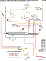
Supplemental Parts List - Electrical Schematic - Charging Circuit
RH NEUTRAL
SWITCH
5021451
STARTER
MOTOR
BATTERY
PTO
SWITCH
5022180
M
L
G
B
S
IGNITION
SWITCH
5020927
A
PARKING BRAKE
SWITCH
5022182
SEAT
SWITCH
5022094
HOURMETER
5100996
PTO CLUTCH
5023233
WHITE
YELLOW
RED
RED
RED
VIOLET
IGNITION SWITCH
POSITION CIRCUIT MAKE
1. OFF G & M & A
2. RUN B & L & A
3. START B & L & S
NEGATIVE BATTERY CABLE
5021406
POSITIVE BATTERY CABLE
5021405
NO
NC
NO
IS3100Z WIRE HARNESS
5401150
COMNONC
85
86
30
87A
87
RELAY
5021766
NC
NC
LH NEUTRAL
SWITCH
5021451
NO
85
86
30
87A
87
RELAY
5021766
AUXILARY
CONNECTOR
BLACK
GREEN
BLUE
BLUE
ORANGE
ORANGE/WHITE
ORANGE/GREEN
ORANGE/WHITE
ORANGE
ORANGE/GREEN
YELLOW
YELLOW
YELLOW
ORANGE
WHITE
WHITE
BLACK
BLACK
WHITE
GRAY
GRAY
BLACK
BLACK
BLACK
BLACK
VIOLET
ORANGE
ORANGE
TIME DELAY MODULE
5023310
1
2
3
4
5
1
R/C
5
4
3
2
TIME DELAY MODULE
SCHEMATIC
BLUE
YELLOW
YELLOW
GRAY
BLACK
ORANGE/WHITE
AUXILARY
SWITCH
YELLOW
ORANGE
WHITE
ORANGE/BLACK
ORANGE/BLACK
ORANGE/BLACK
BLACK
TO JUMPER
HARNESS
BLUE
ORANGE
ORANGE
ORANGE
BLUE
ORANGE
BLUE
BLACK
BLACK
BLACK
ORANGE/WHITE
BLACK
12
3
4
5 6
WHITE
BLACK
20A FUSE
5021603
WHITE
TO TEMP.
GUAGE HARNESS
(LIQUID COOLED ONLY)
WHITE/RED
VIOLET
ORANGE/WHITE
ORANGE/WHITE
TO JUMPER
HARNESS
1
3
5
7
2
4
6
8
FUEL CUT-OFF
VOLTAGE REGULATOR
IGNITION
GROUND
BROWN
BLACK
RED
GRAY
BRIGGS & STRATTON ENGINE
BLACK
BLACK
1
2
3
4
12
PROPANE
SOLENOID
PROPANE FUEL
SOLENOID &
HARNESS
5404096
STARTER SOLENOID
NEGATIVE BATTERY CABLE
5044014 (S/N: 2014809903 & Below)
1
3
5
2
4
6
YELLOW
TO ENGINE
HARNESS
TO MAIN
HARNESS
TO MAIN
HARNESS
1
3
5
7
2
4
6
8
BLACK
VIOLET
WHITE
ORANGE/
WHITE
BLACK BLACK
JUMPER HARNESS
5403508
12
OIL
PRESSURE
SWITCH
NO
NC
COMMON
YELLOW
YELLOW
ORANGE/BLACK
YELLOW
ENGINE
BLOCK
Not for
Reproduction

25
Supplemental Parts List - Electrical Schematic - Cranking Circuit
RH NEUTRAL
SWITCH
5021451
STARTER
MOTOR
BATTERY
PTO
SWITCH
5022180
M
L
G
B
S
IGNITION
SWITCH
5020927
A
PARKING BRAKE
SWITCH
5022182
SEAT
SWITCH
5022094
HOURMETER
5100996
PTO CLUTCH
5023233
WHITE
YELLOW
RED
RED
RED
VIOLET
IGNITION SWITCH
POSITION CIRCUIT MAKE
1. OFF G & M & A
2. RUN B & L & A
3. START B & L & S
NEGATIVE BATTERY CABLE
5021406
POSITIVE BATTERY CABLE
5021405
NO
NC
NO
IS3100Z WIRE HARNESS
5401150
COMNONC
85
86
30
87A
87
RELAY
5021766
NC
NC
LH NEUTRAL
SWITCH
5021451
NO
85
86
30
87A
87
RELAY
5021766
AUXILARY
CONNECTOR
BLACK
GREEN
BLUE
BLUE
ORANGE
ORANGE/WHITE
ORANGE/GREEN
ORANGE/WHITE
ORANGE
ORANGE/GREEN
YELLOW
YELLOW
YELLOW
ORANGE
WHITE
WHITE
BLACK
BLACK
WHITE
GRAY
GRAY
BLACK
BLACK
BLACK
BLACK
VIOLET
ORANGE
ORANGE
TIME DELAY MODULE
5023310
1
2
3
4
5
1
R/C
5
4
3
2
TIME DELAY MODULE
SCHEMATIC
BLUE
YELLOW
YELLOW
GRAY
BLACK
ORANGE/WHITE
AUXILARY
SWITCH
YELLOW
ORANGE
WHITE
ORANGE/BLACK
ORANGE/BLACK
ORANGE/BLACK
BLACK
TO JUMPER
HARNESS
BLUE
ORANGE
ORANGE
ORANGE
BLUE
ORANGE
BLUE
BLACK
BLACK
BLACK
ORANGE/WHITE
BLACK
12
3
4
5 6
WHITE
BLACK
20A FUSE
5021603
WHITE
TO TEMP.
GUAGE HARNESS
(LIQUID COOLED ONLY)
VIOLET
ORANGE/WHITE
ORANGE/WHITE
TO JUMPER
HARNESS
1
3
5
7
2
4
6
8
FUEL CUT-OFF
VOLTAGE REGULATOR
IGNITION
GROUND
BROWN
BLACK
RED
GRAY
BRIGGS & STRATTON ENGINE
1
2
3
4
WHITE/RED
BLACK
BLACK
12
PROPANE
SOLENOID
PROPANE FUEL
SOLENOID &
HARNESS
5404096
STARTER SOLENOID
1
3
5
2
4
6
YELLOW
TO ENGINE
HARNESS
TO MAIN
HARNESS
TO MAIN
HARNESS
1
3
5
7
2
4
6
8
BLACK
VIOLET
WHITE
ORANGE/
WHITE
BLACK BLACK
JUMPER HARNESS
5403508
12
OIL
PRESSURE
SWITCH
NO
NC
COMMON
YELLOW
YELLOW
ORANGE/BLACK
YELLOW
NEGATIVE BATTERY CABLE
5044014 (S/N: 2014809903 & Below)
ENGINE
BLOCK
Not for
Reproduction
/