
Ransomes Way, Ipswich, England, IP3 9QG
RANSOMES
GB
OPERATORS INSTRUCTIONS
Publication No. 24077G (rev.1) (RSJ 001 071997)
CG161 COMPACT
GARDEN TRACTOR


1
PLEASE READ CAREFULLY:
This operator’s manual has been prepared to provide the information you need to correctly assemble, operate
and maintain your tractor. For maximum satisfaction carefully read and follow the instructions in this manual.
Should you ever need repair parts or service contact your RANSOMES TRACTOR DEALER.
Be sure safety precautions are observed. They are for your benefit.
Any references made in this Operator’s Manual concerning the right-or left-hand sides are deter-mined by the
direction the operator is facing when in the tractor seat.
The replacement of any part on this product by other than the manufacturer’s authorised replacement part may
adversely affect the performance, durability or safety of this product.
The manufacturer reserves the right to make changes on and to add improvements upon its product at any time
without notice or obligation. The manufacturer also reserves the right to discontinue manufacture of any product
at its discretion at any time.
A VEHICLE IDENTIFICATION PLATE is located on the left-hand side of the tractor below the engine. The
numbers on the plate are important should your tractor require future service. For your convenience, have your
dealer record the numbers in the appropriate spaces below.

2
CONTENTS
SAFETY PRECAUTION ...................................................................................................... 3
CONTROLS AND INSTRUMENTS ..................................................................................... 7
SEAT.................................................................................................................................... 7
INSTRUMENT PANEL ........................................................................................................ 7
HAND THROTTLE CONTROLS.......................................................................................... 8
BRAKE CONTROLS............................................................................................................8
H.S.T CONTROLS & GEARSHIFT...................................................................................... 9
P.T.O. AND HYDRAULIC LIFT CONTROLS .....................................................................10
STEERING WHEEL............................................................................................................11
OPERATION....................................................................................................................... 12
BREAK IN PROCEDURES................................................................................................. 12
STARTING THE ENGINE................................................................................................... 12
STOPPING THE ENGINE .................................................................................................. 13
OPERATING THE HYDROSTATIC TRANSMISSION ....................................................... 14
DRIVINOTHETRACTOR .................................................................................................... 14
DRAWBAR.......................................................................................................................... 15
TIRE PRESSURES............................................................................................................. 15
LUBRICATION AND MAINTENANCE................................................................................ 16
LUBRICATION AND MAINTENANCE CHART .................................................................. 17
FUEL AND LUBRICANTS .................................................................................................. 18
GENERAL MAINTENANCE ............................................................................................... 26
TRACTOR STORAGE........................................................................................................ 33
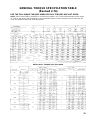
GENERAL TOROUE SPECIFICATION TABLE ................................................................. 35
SPECIFICATIONS .............................................................................................................. 36

3
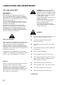
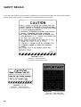
SAFETY RULES
Please pay particular attention to all boxed-
parts in the text which have the sign
This sign warns you to be careful when
carrying out certain functions.
DANGER:
Indicates serious injury or death WILL result if
instructions are not followed.
WARNING:
indicates a strong possibility that serious
injury or death could re suit if instructions are
not followed.
CAUTION:
Indicates a possibility that minor injury can
result if instructions are not followed.
NOTE: Gives helpful information.
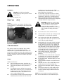
Labels attached to certain parts of the Garden-
tractor give important safety information.
Please read them carefully. Should a label detach
itself or become illegible, contact your dealer for a
replacement.
SAFETY INSTRUCTIONS
TRAINING
1) Read the instructions carefully. Be familiar
with the controls and the proper use of the
equipment. Learn how to stop the engine
quickly.
2) Only use the Garden-tractor for the purpose
for which it was made, that is, the cutting and
collection of grass. Any use not specifically
indicated in the instruction handbook can be
dangerous and result in damage to the ma-
chine, and will also result in the annulling of
the warranty and the manufacturer declining
all responsibility.
3) Never allow children or people unfamiliar with
these instructions to use the Garden-tractor.
Local regulations may restrict the age of the
operator.
4) Never use the Garden-tractor:
l When people, especially children, or pets are
nearby.
l If the operator has taken medicine or
substances that can affect his ability to react
and concentrate.
5) Keep in mind that the operator or user is
responsible for accidents or hazards
occurring to other people or their property.
6) Do not carry passengers.
7) The operator of a Garden-tractor must
carefully follow the driving instructions,
particularly:
l The need for care and concentration when
using Garden-tractors;
l That control of a Garden-tractor sliding on a
slope will not be regained by the application of
the brake.
The main reasons for loss of control are:
l Insufficient wheel grip;
l Being driven too fast;
l Inadequate braking;
l The type of machine is unsuitable for its task;
l Lack of awareness of the effect of ground
conditions, especially slopes;
l Incorrect hitching and load distribution.
8) The Garden-tractor is equipped with a series
of safety microswitches and devices which
must never be removed, altered or tampered
with. Removing these devices invalidates the
warranty and the manufacture declines any
responsibility.
SAFETY

4
SAFETY
PREPARATION
1) While mowing, always wear substantial
footwear and long trousers. Do not operate
the equipment when barefoot or wearing open
sandals.
2) Thoroughly inspect the area where the
equipment is to be used and remove all
objects which may be thrown by the machine
(stones, sticks, metal wire, bones, etc.)
3) WARNING: - Engine fuel is highly flammable:
l Store fuel in containers specifically designed
for this purpose.
l Refuel using a funnel and outdoors only. Do
not smoke while refuelling or whenever
handling the fuel.
l Add fuel before starting the engine. Never
remove the cap of the fuel tank or add fuel
while the engine is running or when the
engine is hot.
l If fuel is spilled, do not attempt to start the
engine but move the machine away from the
area of spillage and avoid creating any source
of ignition until the fuel has evaporated and
the fumes dispersed.
l Tighten caps of all fuel tanks and containers
securely.
4) Replace faulty silencers.
5) Before using, always carry out a visual
inspection, particularly of the blades, seeing
that the screws and cutter assembly are not
worn or damaged. Replace worn or damaged
blades and screws in sets to preserve
balance.
6) Before mowing, attach the discharge opening
guards (grass-catcher or deflector).
7) Take care as the rotation of one blade can
cause the other blade to turn.
OPERATION
1) Do not operate the engine in a confined space
where dangerous carbon monoxide fumes
can collect.
2) Mow only in daylight or good artificial light.
3) Avoid operating the equipment in wet grass,
where feasible.
4) Before starting the engine, disengage the
blades, shift into neutral and engage the
parking brake.
5) Do not use on slopes of more than 100(17%).
6) Remember there is no such thing as a “safe”
slope.
Travel on grass slopes requires particular care. To
guard against overturning:
l Do not stop or start suddenly when going up
or downhill;
l Always keep the machine in gear, especially
when travelling downhill;
l Machine speeds should be kept low on -
slopes and during tight turns;
l Stay alert for humps and hollows and other
hidden hazards;
l Never mow across the face of the slope.
7) Stop the blades rotating before crossing
surfaces other than grass. When moving the
Garden-tractor away from the lawn disengage
the blades and put the cutting plate into the
highest position.
8) Never operate the Garden-tractor as a Cutter-
deck with defective guards, or without safety
devices, for example deflectors and/or grass
catchers, in place.
9) Do not change the engine governor settings
or over speed the engine. Operating the
engine at excessive speed can increase the
hazard of personal injury.

5
SAFETY
10) Before leaving the operator’s position:
l Disengage the blades and lower the Cutter
Deck.
l Charge into neutral and set the parking brake.
l Stop the engine and remove the key.
11) Disengage blades, stop the engine and
remove key:
l Before carrying out any work beneath the
cutting deck or unclogging the chute;
l Before checking, cleaning or working on
Garden-tractor;
l After striking a foreign object. Inspect the
Garden-tractor for damage and make repairs
before restarting and operating the Garden-
tractor;
l If the Garden-tractor starts to vibrate
abnormally (immediately check and remove
the cause of the vibration)
12) Disengage drive to blades when transporting
or not in use. Disengage the blades for them
to stop before emptying the grass-catcher.
13) Stop the engine and disengage blades:
l Before refuelling.
l Every time the grass-catcher is removed or
replaced.
l Before making height adjustment.
14) Reduce the throttle setting during engine shut
down and turn the fuel off at the conclusion of
mowing, following the instructions in the
handbook.
15) Do not put hands or feet near or under
rotating parts. Keep clear of the discharge
opening at all times.
16) Use care when pulling loads or using heavy
equipment.
l Use only approved drawbar hitch paints.
l Limit loads to those you can safely control.
l Do not turn sharply. Use care when reversing.
1 7) Watch out for traffic when crossing or near
roadways.
18) When using any attachments, never direct
discharge of material toward bystanders nor
allow anyone near the machine while in
operation.
MAINTENANCE AND STORAGE
1) Keep all nuts, bolts and screws tight to be
sure the equipment is in safe working
condition. Regular maintenance is essential
for safety and for maintaining performance
levels.
2) Never store the equipment with fuel in the
tank inside a building where fumes may reach
a flame or a spark or a source of extreme
heat.
3) Allow the engine to cool before storing in an
enclosed space.
4) To reduce the fire hazard, keep the engine,
exhaust silencer, battery compartment and
fuel storage area free of grass, leaves, or
excessive grease. Always empty the grass-
catcher and do not leave garden rubbish
containers within a room.
5) Check the deflector and grass-catcher
frequently for wear and deterioration.
6) For reasons of safety, do not use the
equipment with worn or damaged parts. Parts
are to be replaced and not repaired. Use
genuine spare parts. Parts which are not of an
equivalent quality can damage the equipment
and be dangerous for your safety.
7) If the fuel tank has to be drained, this should
be done outdoors and when the engine is
cool.
8) Wear strong work gloves when removing and
reassembling the blades.
9) Check the blades’ balance after sharpening.

6
SAFETY
10) Take care as the rotation of one blade can
cause the other blade to turn.
11) When the machine is to be parked, stored or
left unattended, lower the cutting means.
12) The ignition key must never be left inserted in
the machine, or where children or persons not
familiar to the machine may reach them.
Before any maintenance or repair, remove the
ignition key.

7
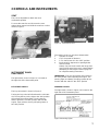
SEAT
The seat is adjustable to obtain the most
comfortable position
To move the seat fore and aft, move the seat
release lever upward and slide the seat fore or aft as
desired, Figure 1.
Figure 1 - Tractor Seat
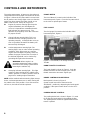
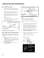
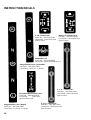
INSTRUMENT PANEL
LIGHT SWITCH
The light switch, shown in Figure 2, is located on
the right side of the instrument panel.
KEY START SWITCH
The key start switch is shown in Figure 2.
Turning the key to the left wilt activate the cold-start
aid. Turning the key 10 the right to the “ON” position
will activate the warning lights. Turning the key
further right to the “START” position will start the
engine. Upon release, the key will spring return to
the “ON” position.
Figure 2 - Instrument Panel
The starting circuit can only be activated when
1. Operator is seated,
2. H.S.T foot pedal is released.
3. P.T.O clutch lever is in the “OFF” position.
4. Brake pedal is depressed or parking brake
lever is locked.
Always check to make certain the range shift
lever and lift control lever are in neutral before
attempting to start engine. Refer to page 19
for complete starting instructions.
IMPORTANT : The key start switch must remain in
the “ON” position while operating the engine. The
warning lights and battery charging system will not
function with the switch in the “OFF” position
WARNING LIGHTS
The light switch, shown in Figure 3 is located on the
right side of the instrument panel.
Figure 3-Warning Lights
CONTROLS AND INSTRUMENTS

8
CONTROLS AND INSTRUMENTS
The engine temperature, oil pressure, glow plug and
charge indicator warning lights are located as shown
in Figure 3, When the key start switch is turned “ON”
the oil pressure and charge lights come on. After the
engine has been started, the lights should go out
within a few seconds. If they do not go out:
l Engine oil pressure warning light: Stop the
engine immediately and investigate the
cause. It is important to remember that this
light indicates OLI pressure only. The
operator must regularly check the crankcase
for proper oil level.
l Charge indicator warning light: This is an
indication that the charging system is not
operating normally. Investigate the cause as
soon as possible, otherwise the battery will
become fully discharged.
l Coolant temperature warning light: The
warning light is not on under normal operating
conditions. If the light comes on, stop the
engine and investigate. Regularly check the
radiator for proper coolant level. Function of
the indicator light bulb can be checked by
grounding this light at the thermostat.
WARNING: When engine is at
operating temperature always relieve
pressure in the cooling system before
removing the radiator cap.
l Glow plug indicator warning light : This light
comes on when turning the key switch to the
“HEAT” position or “START” position. Refer to
page 19 for ‘starting engine information.
NOTE: Make certain that three warning lights except
for the coolant temperature turn on when turning the
key switch to the “ON” position. If one of them does
not turn on, the bulb should be replaced.
PROOF-METER
The Proof-Meter is located on the left side of the
instrument panel, Figure 4. Turn the key start switch
to the “ON” to operate proof meter.
FUEL GAUGE
The fuel gauge is located on the left side of the
instrument panel, Figure 4.
Figure 4 - Proof Meter, Fuel Gauge and Hand
Throttle
HAND THROTTLE CONTROLS
The hand throttle is shown in Figure 2. Push the
throttle forward to increase engine rpm Pull the
throttle rearward to decrease engine rpm
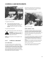
BRAKE CONTROLS BRAKE PEDAL
Brake pedal is shown in Figure 5.
Speed control lever will be returned to the
“RELEASE” position by depressing the brake pedal
suddenly, if the speed control lever is in the “SET”
position
PARKING BRAKE CONTROL
The parking brake latch, shown in Figure 5, is used
for locking the brake pedal in the applied position.
The parking brake should be applied whenever the
tractor is parked.

9
CONTROLS AND INSTRUMENTS
Figure 5 - Brake Controls
To apply the parking brake:
l Pull up the parking brake latch while
depressing the brake pedal. The pawl on the
control will engage the teeth on the brake
pedal and will retain the pedal in the applied
position.
To release the parking brake
l Depress the brake pedal to release the pawl.
WARNING: Do not park on an incline. If
necessary to park there be sure to
chock the wheels to prevent accidental
rolling of the machine.
NOTE: The parking brake must be applied to start
the engine
H.S.T. CONTROLS & GEARSHIFT
H.S.T.FOOT PEDAL
The ground speed of tractors equipped with the
hydrostatic transmission Is continuously variable,
from zero to full rated speed in each range. Speed is
controlled by the H.S.T. foot pedal on the right side
of the transmission, Figure 6. Depress the forward
pad on the pedal for forward travel, to the position
that provides the desired ground speed. For reverse
travel, depress the rear pad on the pedal.
Releasing the pedal returns the transmission to
Neutral, and stops the tractor, unless the speed
control lever is in the “SET” position.
NOTE: The H.S.T. foot pedal must be in neutral to
start the engine
Figure 6 - HST Control
SPEED CONTROL LEVER
The speed control lever, Figure 6, may be used to
maintain a constant forward speed when desired.
After attaining the desired speed with the forward
pedal pad, move the lever to the “SET” position, and
the tractor will maintain the set speed even if the
pedal is released.
To cancel the speed setting or stop the tractor move
the speed control lever to the “RELEASE” position
or firmly depress the brake pedal. If a higher or
lower set speeds is desired, release and reset the
lever.
WARNING: To avoid injury, the lever should not be
put in the “SET” position when operating at high
speed or when in reverse.
Do not move the speed control lever to the SET
position while applying the parking brake.

10
CONTROLS AND INSTRUMENTS
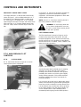
GEARSHIFT - RANGE SHIFT LEVER
The range shift lever, on the left side of the fender,
shown in Figure 7, can be shifted when the H.S. T
foot pedal is in the Neutral position, to High range
“H”, Low range “L” or Neutral “N”. In “H”, forward
speed ranges from zero to 13 kph, and reverse from
zero to 6.5 kph. In “L”, forward speed ranges from
zero to 6..5 kph, and the reverse range is zero to 3
kph.
Figure 7 Range Shift Lever
P.T.O. AND HYDRAULIC LIFT
CONTROLS
P.T.O. CLUTCH LEVER
P.T.O. clutch lever shown in Figure 8. is used to
control power input to equipment.
Figure 8 - P.T. 0 Clutch Lever
Push the P.T.O. clutch lever forward to operate the
equipment. Pull the lever rearward to stop the
equipment. Mid mounted equipment is driven with
V-belts from the engine.
NOTE: The P.T.O. clutch lever must be placed in
the “OFF” position to start the engine.
WARNING: To avoid injury when the
P.T.O. driven equipment is not used,
the P.T.O. clutch lever must be placed
in the “OFF” position.
LIFT CONTROL LEVER
The lift control lever is shown in Figure 9, and is
located on the right side of the fender. The mid-
mounted equipment can be raised and lowered by
the lift control lever. Four positions are provided in
the lift control lever, i.e. RAISE, LOCK, LOWER, and
MOW for mowing operation.
Figure 9 - lift Control Lever
Set the lift control lever in MOW only for mowing
operation. The lever will hold at this position.
Floating of the mower is obtained in this position
permitting the mower to touch the ground lightly
during mowing operation. This position transfers
maximum weight to the tractor rear wheels for
increased traction.
It is necessary to set the lever in MOW after gauge
wheels have touched the ground while pushing the
lever from LOCK to LOWER. Passing directly from
LOCK to MOW may not allow the deck to go down
to the cutting height set by the gauge wheels. Be
sure to hold the lever in the LOWER position
momentarily before going into the MOW position.

11
CONTROLS AND INSTRUMENTS
NOTE: The lift control lever must be placed in the
“LOCK” position to start the engine.
NOTE: The hydraulic oil flows to the power steering
system first so that the mid mounted equipment may
not raise when operating the power steering, even if
the lift control lever has been moved to the RAISE
position.
WARNING: To avoid personal injury
never operate mower with the lift
control lever in raised position. Mower
must be lowered completely before
operating.
STEERING WHEEL
The steering wheel is adjustable to obtain the most
comfortable position
To move the steering wheel fore and aft, push the
steering wheel release lever downward and move
the steering wheel fore or aft as desired, Figure 10.
Figure 10 - Steering Wheel

12
OPERATION
BREAK-IN PROCEDURES
Your RANSOMES Tractor will provide long and
dependable service if given proper care during the
50-hour break-in period During the first 50 hours of
operation:
1. Avoid “lugging” the engine. Operating in too
high a gear under heavy load may cause
engine “lugging”, which is indicated when the
engine will not respond to a throttle increase.
2. Use the lower gear ratios when pulling heavy
loads and avoid continuous operation at
constant engine speeds. You will save fuel
and minimise engine wear by selecting the
correct gear ratio for a particular operation.
Operating the tractor in low gear with a light
load and high engine speed will waste fuel
3. Avoid prolonged operation at either high or
low engine speeds without a load on the
engine.
4. Check the instruments frequently and keep
the
radiator and oil reservoirs filled to their
recommended levels.
Daily checks include:
l Engine oil level
l Air cleaner
l Belt tension
l Radiator coolant
STARTING THE ENGINE
Neutral start switches on the tractor allow the
starting motor to be used only when the H.S.T. foot
pedal is released, the P.T.O. clutch lever is in the
“OFF” position when the brake pedal is depressed
and the operator is in the seat. For safe operation
the shift lever and lift control lever should be in
“LOCK” position prior to starting the engine.
WARNING: To avoid injury, never
attempt to start the engine while
standing beside the tractor always sit
in the seat when starting the engine.
IMPORTANT: Do not engage the starting motor
continuously for more than 10 seconds; doing so
may cause starting motor failure.
STARTING
To start the engine:
1. Move the shift lever and lift control lever to the
neutral position
2. Move the hand throttle forward to a near full
open position.
3. Turn the key start switch to the “HEAT” to
preheat the precombustion chambers and
wait until the glow plug indicator warning light
on the instrument panel goes out. (for 4
seconds approximately)
4. Turn the key start switch to the “START”
position, Figure 11. \/\/hen the engine starts,
release the key. Check to be sure the warning
lights go out.
Figure 11- Key Start Switch
WARNING: To avoid injury, do not use
ether with the thermostart starting aid.
NOTE: A coolant immersion heater which provides
for easier starting in temperatures below O°F (-1 7-
70°C) by warning the engine oil and coolant is
available as a dealer installed option.
NOTE: If the engine develops sufficient speed to
disengage the starter but does not keep running (a
“false start”), the engine rotation must be allowed to
come to a complete stop before attempting to restart
the engine. If the starter is engaged while the
flywheel is rotating, the starter pinion and flywheel
ring gear may clash, resulting in damage to the
starter.

13
OPERATION
If the starter does not turn the engine over, shut off
starter immediately. Do not make further attempts to
start the engine until the condition is corrected.
SAFETY INTERLOCK SWITCHES
Your RANSOMES tractor is equipped with three
interlock switches, P T 0 clutch lever, brake and
seat. The engine can be started only when the
P.T.O. clutch lever is in the “OFF” position and when
the brake pedal is depressed. If even one of them is
not applied the engine cannot be started. The
engine will continue to run without an operator in the
seat only if the brake pedal is locked down and
P.T.O. clutch is disengaged.
STARTING THE TRACTOR WITH JUMPER
CABLES
WARNING: To avoid injury always start
engine from the operator’s seat. If
safety start switch is bypassed, engine
can start with transmission in gear.
If it is necessary to use jumper cables to start the
tractor, follow the instructions below;
1 Shield eyes.
2. Connect one end of the jumper cable to the
tractor battery positive (+) terminal and the
other to the auxiliary battery positive (+)
terminal. Connect one end of the other cable
first to the auxiliary battery negative (-)
terminal, and the other end to the tractor
starter ground terminal. Follow the starting
procedures above after the jumper cables are
connected as instructed.
Idle the engine and turn on electrical equipment
(lights, etc.) , then disconnect the cables in reverse
order of the connecting procedure above. This will
help protect the alternator from damage due to
extreme load changes.
WARNING: Batteries contain sulphuric
acid and produce explosive gases.
Follow the instructions below to prevent
personal injury.
l Wear eye and skin protection.
l Keep sparks and flame away.
l Always have adequate ventilation while
charging or using the battery.
l Follow the battery manufacturer’s instructions
which are shown on the battery.
l If ice is present or the battery is cracked, DO
NOT ATTEMPT TO “JUMP START” vehicle.
l Bring helper vehicle with a battery of the
same voltage as disabled machine within
easy cable reach “THE VEHICLES MUST
NOT TOUCH”.
STOPPING THE ENGINE
Stopping the engine should be done according to
the following procedures,
Pull the throttle lever fully rearward.
2. Place the speed control lever in the
“RELEASE” position, and release the H.S.T.
foot pedal.
3. Set and lock the brake pedal.
4. Place the range shift and lift control levers in
the “LOCK” position.
5. Turn the key start switch to the “OFF”
position.
6. Remove the key
IMPORTANT: Failure to turn the key start switch to
the “OFF” position after the engine stops will allow
the warning lights to remain on, causing the battery
to discharge.

14
OPERATION
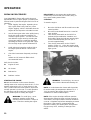
OPERATING THE HYDROSTATIC
TRANSMISSION
HYDROSTATIC TRANSMISSION
The hydrostatic transmission is controlled by the
H.S.T.foot pedal, speed control lever, shown in
Figure 13. and range shift lever shown in Figure 7.
Figure 13 - HST Controls
When operating the range shift lever, place the H.S.
T. foot pedal in neutral position. If it is difficult to
engage, slightly depress the foot pedal for smooth
engagement.
Never engage or disengage the shift lever when the
tractor is in motion.
With the shift lever in “H” range, ground speed can
be varied from zero to maximum by depressing the
forward or reverse pad on the foot pedal. In L”
range, speeds are about 50% of maximum.
Maximum speeds in reverse are about a half of
maximum forward speeds.
For prolonged operation at a fixed forward speed,
use the forward pedal pad to attain the desired
speed, then move the speed control lever to the
“SET” position. The speed will remain at the set
value when the pedal is released. To change the
tractor speed, move the speed control lever to the
“RELEASE” position, use the foot pedal to attain the
desired speed. then move the speed control lever to
the “SET” position again.
To stop the tractor, place the speed control lever in
the “RELEASE” position without depressing the foot
pedal. When the speed control lever is in the
“RELEASE” position, release the foot pedal, and it
will return to the neutral position automatically,
stopping the tractor.
Or to stop the tractor, depress the brake pedal, and
the speed control lever returns to the “RELEASE’:
position (if in SET position) and the H.S. T. foot
pedal returns to the neutral position.
DRIVING THE TRACTOR
WARNING: To prevent personal injury,
observe the following precautions
when driving the tractor.
l Watch where you are going-especially at row
ends, on roads, and around trees.
l Keep the tractor in gear when going down hill.
Use a low gear to maintain control.
l If the tractor is stuck, back out to prevent
upsetting the unit.
l Do not pull from any other part than the draw-
bar of the tractor since it may tip backward.
l Reduce speed before turning quickly or
applying brake.
l Use extreme caution and avoid hard
applications of the tractor brake when pulling
heavy towed loads at road speeds.
l Towed loads that weigh more than twice the
weight of the tractor should have brakes. If
not, reduce speed and avoid inclines.
l Always sit in the tractor seat while starting or
driving the tractor

15
OPERATION
DRAWBAR
Warning: Pull only from drawbar.
Pulling from any other point can cause
rear overturn
The maximum drawbar load
Pulling - load: 340 kg
Vertical - load: 140 kg
Towing
Towing this machine, set the gear shift lever to the
neutral position. If not, damage to the transmission
may result.
Figure 22 - Drawbar
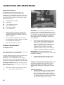
TYRE PRESSURE
Tire pressure must be considered when adding
weight to the tractor. The following “TYRE
INFLATION vs. PERMISSIBLE LOAD” table lists
the tire size available and shows the maximum load
the tire can carry for a given air pressure. Note that
the load capacities decrease as inflation pressures
decrease.
TYRES
Inflation and Service
l Upon receiving your tractor, check the air
pressure in the tires as indicated in the tables.
l Check the tire pressure every 50 hours, or
weekly.
l Tire inflation pressure affects the amount of
weight which a tire may carry. Locate the tires
for your tractor in the “ TIRE INFLATION vs.
PERMISSIBLE LOAD” chart below. Do not
over or under inflate the tires.
l Do not Inflate a tire above the manufacturer’s
maximum pressure shown on the tire or the
maximum pressure shown in the “TIRE
INFLATION vs. PERMISSIBLE LOAD” chart,
below if the tire is not marked.
l Do not inflate a tire that has been run flat or
seriously under-inflated until the tire has been
inspected for damage by a qualified person.
l When checking tire pressure, inspect tire for
damaged side walls and tread cuts. Neglected
damage will lead to early tire failure.
WARNING: Inflating or servicing tires
can be dangerous. Trained personnel
should be called to service and/or
mount tires when possible. In any
event to avoid possible serious or fatal
injury, follow the safety precautions
below.
l Be sure the rim is clean and free of rust.
l Lubricate both tire beads and rim flanges with
soap solution. Do not use oil or grease.
l Use a clip-on tire chuck with a remote hose
and gauge which allows the operator to stand
clear of the tire while inflating it.
l NEVER INFLATE TO OVER 35 psi (241 kpa).
TO SEAT BEADS. If beads have not seated
by time pressure reaches 35 psi, deflate the
assembly, reposition tire on rim, relubricate
both tire beads and rim flanges and re-inflate.
Inflation beyond 35 psi with unseated beads
may break the bead or rim with explosive
force sufficient to cause serious injury.
l After seating the beads, adjust inflation
pressure to recommended operating
pressure.
l Do not inflate a tire unless the rim is mounted
on the tractor or is secured so that it will not
move if the tire or rim should suddenly fail.
l Do not weld, braze, otherwise repair, or use a
damaged rim.
l Never attempt tire repairs on a public road or
highway.
l Use jack stands or other suitable blocking to
support the tractor while repairing tires.
l Insure jack has adequate capacity to lift your
tractor.
l Insure jack is placed on a firm level surface.
l Do not put any part of your body under the
tractor or start the engine while the tractor is
on the jack.
NOTE: Do not exceed the maximum load listed.
Also do not under-inflate or over-inflate the tyres.

16
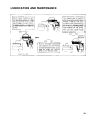
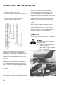
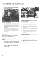
LUBRICATION AND MAINTENANCE

17
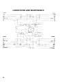
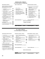
LUBRICATION AND MAINTENANCE
NO
LUBRICATION AND
MAINTENANCE
ITEMS
C
H
E
C
K
C
L
E
A
N
L
U
B
E
C
H
A
N
G
E
A
D
J
U
S
T
SERVICE
INTERVALS
6 Radiator Coolant X
Every
10 Hours
or Daily
1 Engine Oil Level X
15 Air Cleaner X
2 Belt Tension X
12
Transmission and Rear
Axle Oil
X
Every
10
Hours
or Daily
3 Battery X
15 Air Cleaner Element X
9 HST Line Filter X
Hours
10 HST Suction Filter X
12
Transmission and Rear
Axle Oil
X
1 Engine Oil X
14 Fan Belt X X
17 Fuel Filter DRAIN
50
Hours
16 Tyres X
7 Brake Pedal X X X
Lubrication Fittings
7 Pedal Shaft X
8 Speed Control Lever X
NO
LUBRICATION AND
MAINTENANCE
ITEMS
C
H
E
C
K
C
L
E
A
N
L
U
B
E
C
H
A
N
G
E
A
D
J
U
S
T
SERVICE
INTERVALS
Lubrication Fittings
Every
50
Hours
13 PTO Clutch Lever X
2 Belt Tension Pulley X
5 Steering Linkage X
17 Fuel Filter X
Every
100
Hours
1 Engine Oil X
9 HST Line Filter X
17 Fuel Filter Element X
Every
200
Hours
14 Fan Belt X X
18 Engine Oil Filter X
11 Brake X
10 HST Suction Filter X
12
Transmission and Rear
Axle Oil
X
19 Fuel Injectors X
Every
600
Hours
20 Fuel Pre-Filter X
6 Radiator Coolants X
Seasonal
15 Air Cleaner Element X

18
LUBRICATION AND MAINTENANCE
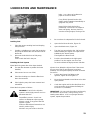
FUEL AND LUBRICANTS
FUEL (DIESEL
Type of fuel to use
When operating in temperatures above 20~F (-
6.7C), use diesel fuel oil No.2-D with a minimum
cetane rating of 40. When operating in temperatures
below 20F (-6.7C), use diesel fuel oil No. 1 -D with a
minimum cetane rating of
40. Low ambient temperatures as well as engine
operation or high altitudes may require use of fuels
with higher cetane ratings.
Fuel represents a major portion of your tractor
operating costs; therefore, it is important to use it
efficiently. Do not let low price tempt you to use
inferior diesel fuel. The Initial savings is a false
economy when you consider the damage poor fuel
can do to your tractor fuel system.
FUEL USAGE SAFETY
Fuel is becoming very expensive and scarce. As a
result, many of our customers are trying new fuels or
blends to reduce costs and conserve energy.
Today’s new fuels or blends are frequently more
volatile and there is a need to handle them carefully.
Furthermore, some of the blends are dangerous and
should not be used at all.
The following new or blended fuels are becoming
available or are sometimes recommended by certain
sources. Our recommendations are as follows:
Diesel oil
Under no circumstances should gasoline, alcohol or
gasohol be added to diesel fuel. These
combinations can create an increased fire hazard
and under certain circumstances an explosive
hazard. They are more dangerous (explosive ) than
pure gasoline in a closed container such as fuel
tank. Do Not Use These Blends.
WARNING: Fuel oil in the injection
system is under high pressure and can
penetrate the skin. Unqualified persons
should not remove or attempt to adjust
a pump injector, nozzle or any part of
the fuel injection system.
Failure to follow these instructions can
result in serious injury.
DO NOT use your hand to check for
leaks. Use a piece of cardboard or
paper to search for leaks.
If any fluid is injected into the skin,
obtain medical attention immediately or
gangrene may result.
WARNING
l Never remove the fuel cap or refuel the tractor
when the engine is running or is hot.
l Don’t smoke while refuelling or while
anywhere near fuel.
l When filling the tank, maintain control of the
nozzle.
l Don’t fill the fuel tank to capacity “allow room
for expansion.
l Wipe up spills immediately.
l Always tighten the fuel tank cap securely
l If the original equipment fuel tank cap is lost,
always replace it with an approved cap. A
will-fit cap may not be safe.
l Keep equipment properly maintained.
l Keep equipment clean - free of trash and oil.
l Don’t drive equipment near open fires.
l Never use gasoline for cleaning parts.
LUBRICANTS
Page is loading ...
Page is loading ...
Page is loading ...
Page is loading ...
Page is loading ...
Page is loading ...
Page is loading ...
Page is loading ...
Page is loading ...
Page is loading ...
Page is loading ...
Page is loading ...
Page is loading ...
Page is loading ...
Page is loading ...
Page is loading ...
Page is loading ...
Page is loading ...
Page is loading ...
Page is loading ...
Page is loading ...
Page is loading ...
Page is loading ...
Page is loading ...
Page is loading ...
Page is loading ...
Page is loading ...
Page is loading ...
Page is loading ...
Page is loading ...
Page is loading ...
Page is loading ...
Page is loading ...
Page is loading ...
-
 1
1
-
 2
2
-
 3
3
-
 4
4
-
 5
5
-
 6
6
-
 7
7
-
 8
8
-
 9
9
-
 10
10
-
 11
11
-
 12
12
-
 13
13
-
 14
14
-
 15
15
-
 16
16
-
 17
17
-
 18
18
-
 19
19
-
 20
20
-
 21
21
-
 22
22
-
 23
23
-
 24
24
-
 25
25
-
 26
26
-
 27
27
-
 28
28
-
 29
29
-
 30
30
-
 31
31
-
 32
32
-
 33
33
-
 34
34
-
 35
35
-
 36
36
-
 37
37
-
 38
38
-
 39
39
-
 40
40
-
 41
41
-
 42
42
-
 43
43
-
 44
44
-
 45
45
-
 46
46
-
 47
47
-
 48
48
-
 49
49
-
 50
50
-
 51
51
-
 52
52
-
 53
53
-
 54
54


Ask a question and I''ll find the answer in the document
Finding information in a document is now easier with AI
Related papers
-
Ransomes 67003, 67004 Owner's manual
-
-
-
-
-
-
-
Ransomes 84043, 84044, 898627, 898628, 84052 Owner's manual
-
-
Other documents
-
Univex Clipper 385002X108 User manual
-
Univex Clipper 405012X108 User manual
-
New Holland TD 70D User manual
-
Shibaura ST333 User manual
-
-
Mitsubishi diesel engines User manual
-
-
-
-