Minicom Advanced Systems 3000 User manual
- Category
- Networking
- Type
- User manual
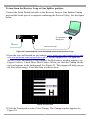
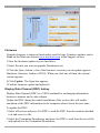
Minicom Advanced Systems 3000 is an out-of-band solution for the last step in a digital signage network. It combines video, stereo/audio and serial functions for distributing real-time multimedia content from player to multiple screens up to 300m/1,000ft away. With the DS Vision an administrator can remotely turn the distributed screens on and off, and monitor them either separately or as a unified group. The system also supports Display Data Channel (DDC) signaling, enabling optimal player-screen configuration for better visual experience.
Minicom Advanced Systems 3000 is an out-of-band solution for the last step in a digital signage network. It combines video, stereo/audio and serial functions for distributing real-time multimedia content from player to multiple screens up to 300m/1,000ft away. With the DS Vision an administrator can remotely turn the distributed screens on and off, and monitor them either separately or as a unified group. The system also supports Display Data Channel (DDC) signaling, enabling optimal player-screen configuration for better visual experience.


-
 1
1
-
 2
2
-
 3
3
-
 4
4
-
 5
5
-
 6
6
-
 7
7
-
 8
8
-
 9
9
-
 10
10
-
 11
11
-
 12
12
-
 13
13
-
 14
14
-
 15
15
-
 16
16
-
 17
17
-
 18
18
-
 19
19
-
 20
20
-
 21
21
-
 22
22
-
 23
23
-
 24
24
-
 25
25
-
 26
26
-
 27
27
-
 28
28
-
 29
29
-
 30
30
-
 31
31
-
 32
32
-
 33
33


Minicom Advanced Systems 3000 User manual
- Category
- Networking
- Type
- User manual
Minicom Advanced Systems 3000 is an out-of-band solution for the last step in a digital signage network. It combines video, stereo/audio and serial functions for distributing real-time multimedia content from player to multiple screens up to 300m/1,000ft away. With the DS Vision an administrator can remotely turn the distributed screens on and off, and monitor them either separately or as a unified group. The system also supports Display Data Channel (DDC) signaling, enabling optimal player-screen configuration for better visual experience.
Ask a question and I''ll find the answer in the document
Finding information in a document is now easier with AI
Related papers
-
Minicom Advanced Systems 3000 User manual
-
-
-
-
-
-
-
-
-
Other documents
-
Kramer Electronics BC-2S-300M Datasheet
-
-
Minicom VGA Extender User manual
-
Tripp Lite Minicom Power-On Cable Quick start guide
-
Digitus DS-52110 Owner's manual
-
-
-
-
Black Box AC3016A-R2 Specification
-
Ultratec Minicom IV User manual