Page is loading ...

NOR1.01,11
INSTALLATION AND OPERATING
INSTRUCTIONS
682
683
662
663
WARNING
Improper installation, adjustment, al-
teration, service, or maintenance can
cause injury or property damage. Re-
fer to this manual. For assistance or
additional information consult a quali-
fied installer, service agency, or the
gas supplier.
FOR YOUR SAFETY
Do not store or use gasoline or other
flammable vapors and liquid in the vi-
cinity of this or any other appliance.
FOR YOUR SAFETY
If you smell gas:
1.
Open windows
2.
Do not touch any electrical
switches
3.
Extinguish any open flame
4.
Immediately call your gas supplier
Contents
Safety Precautions
1
Extended Service Protection Plan
3
Ventilation Requirements
4
Installation Instructions
7
Decorative Door Panel Installation
11
Reversing Door Swing
11
Lighting and Start-Up Instructions
15
Operating and User Instructions
17
Refrigerator Care
22
Refrigerator Maintenance
22
Failure of Refrigerator
23
Replacement Parts
23
Information About LP Gas
24
Wiring Diagrams
25
Warranty
27
This refrigerator has been designed to operate on the following energy sources:
LP GAS OPERATION - 11.0 inches Propane & 12 volt DC control voltage (15.4 volts max., 10.5 volts min.).
AC OPERATION - 120 volts AC (132 volts max., 108 volts min.) and 12 volt DC control voltage.
DC OPERATION - [3-WAY MODELS] 12 volts DC (15.4 volts max., 11.5 volts min.).
Operation
where
these specifications are exceeded may cause damage and will void the warranty.
MODEL NO.
SERIAL NO.
The location of the model number and serial number may be found attached to the lower front panel of
the refrigerator. (See Figure 24)
Part No.: 616682J (93-03)

Safety Precautions
Read this manual and become thoroughly acquainted with it before installing or starting
the refrigerator. The following safety precautions and recommendations contained herein
are for your protection.
Improper installation, adjustment, or operation can cause injury or property damage.
The safety symbols used in this manual contain Safety Alert information. Understand
their meanings and be safety conscious.
A SITUATION WHICH, IF NOT AVOIDED,
WILL
RE-
SULT IN DEATH OR SERIOUS INJURY.
A
DANGER
A SITUATION WHICH, IF NOT AVOIDED,
COULD
RE-
SULT IN DEATH OR SERIOUS INJURY.
A
WARNING
A SITUATION WHICH, IF NOT AVOIDED, MAY RE-
SULT IN MINOR OR MODERATE INJURY.
A
CAUTION
General
•
Keep the unit and surrounding area clean. Never use the area behind refrigerator for
storage; in particular, storing flammable materials (oily rags, paper, aerosol cans,
and chemicals.). Stored materials not only present a safety hazard but could block
the ventilation to the system.
•
Provide appropriate fire extinguishers installed in convenient locations. Consult
your local fire department for the correct type to use. Do not use foam on electrical
fires. Use extinguisher rated by NFPA.
•
Make sure all fasteners, supports, seals, electrical covers are secure.
LP Gas System
•
LP gas is highly flammable. Gas connections must be leak tight. Do not smoke,
create sparks or use an open flame when checking gas connections. Do not ignore
the "rotten egg" smell of gas fumes.
•
Protect all gas lines from physical damage, vibration, or excessive heat.
•
Insure that the supply gas pressure is within the tolerance specified on the front
cover of this manual. The gas controls are designed for safety. Never tamper with
the adjustment or function of the controls other than as directed by the Lighting and
Shutdown Instructions. All repairs must be done by a qualified service person.
Exhaust Gases
•
Proper ventilation to remove exhaust gases is extremely important. These gases,
generated in the GAS mode at the rear of the refrigerator, replace the oxygen in the
air and in extreme cases can produce dangerous levels of carbon monoxide. This
manual contains installation instructions to safely remove the exhaust gases and
seal the zone from the living area. The installation instructions are certified by
American Gas Association and Canadian Gas Association and must be followed.
•
Check the burner for proper flame characteristics at the initial start-up and at least
once every year. The information for this check is located in this manual and must
be performed by a qualified service person.
1

Safety Precautions -
continued
Electrical Circuits - AC and DC
•
The 120 volt AC circuit must be properly grounded. Never cut or remove the round
grounding prong from the refrigerator's AC cord. Do not use a two-prong adapter.
Do not use an extension cord to connect to the approved AC receptacle.
•
Protect all wiring from physical damage, vibration, or excessive heat.
•
Always disconnect both AC and DC sources of power when working on either cir-
cuit (only a qualified service person).
•
Insure all terminating connections are clean and tight to prevent arcing or over-
heating.
•
Never allow Leak Detecting fluids or any other liquids to spill on electrical connec-
tions. Many liquids are electrically conductive and could cause serious arcing dam-
age and, in some case, fires.
Refrigerant System
•
Never physically bend, drop, drill, weld, or hammer the refrigerant system. Doing so
could cause the system to rupture and release dangerous chemicals which can
cause severe burns to the eyes or skin. If ignited, these chemicals will burn with
intense flame. A leaking system can release certain chromium components which, if
inhaled, can cause cancer.
•
Never apply direct heat in excess of 240' F to the refrigerant system. Because the
refrigerant is hermetically sealed under pressure, a temperature sensitive safety de-
vice opens to protect the system from erupting under excessive pressure. However,
the expelled refrigerant could ignite and burn if an ignition source were near.
•
Never attempt to repair or recharge the refrigerant system. If defective, it must be
replaced.
Child Entrapment
•
Never install door locks or other restraints which could entrap small children within
the refrigerator. The Travel Latch system must not be modified.
Handling the Refrigerator
•
Never lift the refrigerator without assistance. Protect yourself from body strain.
•
Avoid hot surfaces at the rear of the refrigerator when operating. The absorption
type refrigerator produces several hot areas at the rear of the unit. This is true
whether in GAS or ELECTRIC mode.
•
Take care to avoid brushing against the irregular shapes and sheet metal parts at
the rear of the refrigerator. Cuts or abrasions could result.
2

*NORCOLD E.S.P.
Models 662, 663, 682, and 683
EXTENDED COOLING UNIT SERVICE PROTECTION PLAN
An additional four year Service Contract is now
E.S.P. is a service contract between Norcold and
available to original purchasers of Norcold refrig-
the original purchaser. The contract provides re-
erators. For only $40.00 you get:
placement of a defective cooling unit only for this
refrigerator (freight, parts, and labor) for an addi-
*
Four extra years protection against cooling unit
tional period of four years after expiration of the
failure.
original Limited Warranty. The refrigerator must be
delivered to Norcold Service Center together with
•
Automatic replacement of defective cooling unit.
the Norcold E.S.P. card showing E.S.P. coverage.
An E.S.P. card will be mailed to the original pur-
• Pre-paid freight from your dealer to Norcold and
chaser upon receipt of a completed Service Con-
return.
tract Application form and a check covering the
E.S.P. charge. E.S.P. coverage is non-transferable
•
Labor free of charge.
and non-refundable.
To register your refrigerator, fill out the warranty
The E.S.P. (Extended Service Protection) plan
Service Contract Application - i.e.: Tear Sheet
can be obtained by mailing your check for $40.00*,
Form in yellow envelope or include the following
U.S. funds to:
information (Please Print Clearly):
NORCOLD
P 0 BOX 4248
SIDNEY OH 45365-4248
If mailing in Canada:
GREG LUND PRODUCTS LTD
P
0
BOX 760
OAKVILLE ONTARIO CANADA L6J 5C4
1.
Owner's name and address.
2.
Refrigerator model number.
3.
Refrigerator serial number.
4.
Date of purchase.
5.
Check for $40.00* (payable to Norcold).
Applications will be accepted only if they are mailed
within ninety (90) days
after
date of purchase.
*Ohio residents, add $2.60 sales tax.
General Instructions - All Models
The refrigerators described herein are designed and
certified for built-in installations. They must be in-
stalled on a solid floor and secured by screws
THIS REFRIGERATOR IS NOT INTENDED TO BE
through holes provided. In making provisions for the
OPERATED AS A FREE STANDING UNIT (I.E.
installation, the following must be considered:
WHERE THE PRODUCTS OF COMBUSTION ARE
a.
Adequate ventilation (See section on "Ventila-
NOT COMPLETELY SEALED OFF FROM THE LIV-
tion Requirements").
ING AREA) OR INSTALLED IN SUCH A WAY AS
b.
Minimum clearance to combustible materials: 0"
TO CONFLICT WITH THESE INSTALLATION IN-
back, sides, bottom, top, is acceptable on these
STRUCTIONS. UNAPPROVED INSTALLATIONS
models.
COULD RESULT IN SAFETY RISKS OR PER-
c.
Adequate seal between refrigerator mounting
FORMANCE PROBLEMS.
flange and cut-out opening. (See Figure 12)
A
WARNING
3

0" best
1" max. allowable
If rear clearance is
greater than 1",
see Figure 2.
615791
615998
616009
616010
616066
3
Certified Lower
Certified
Vent Door
Roof Jack
Models
Kit Number
662, 663
682, 683
VENTILATION REQUIREMENTS
Installation must assure complete isolation of the
living space of the mobile home or recreational vehi-
cle and the combustion system of the refrigerator.
Certified installation requires that one lower com-
bustion air intake and one upper exhaust vent be
used. Not only must the combustion kits be installed
correctly, but the construction around the rear of the
refrigerator allow good circulation and seal off the
combustion products from the living space. Cut-Out
dimensions for factory supplied vents are shown in
TABLE 1. The specified vent kit for this refrigerator,
certified by A.G.A. and CGA, must be installed as
directed by this manual without modification. Any de-
viation or substitution other than the specified vent
kit will void this certification and the factory war-
ranty of the refrigerator.
A.G.A./CGA certification permits installing the refrig-
erator with zero inch (0") minimum clearance at the
sides, back, top, and bottom. This certification does
not specify any maximum clearance. However, the
clearances around the sides and rear should be mini-
mized in order to create a proper air draft necessary
for good refrigerator performance. The condenser
and absorber tubes must receive a continual supply
of cooler air in order to maintain proper refrigerator
cooling. The air passage (ventilation zone) from the
lower vent door to the refrigerator coils and from the
coils up through the roof vent must be unobstructed.
A
WARNING
INADEQUATE VENTILATION OR PARTIAL BLOCK-
AGE OF FLUE EXHAUST CAN PRODUCE CARBON
MONOXIDE WHILE OPERATING IN GAS MODE. IN-
HALING FUMES CAN CAUSE DIZZINESS, NAUSEA,
OR IN EXTREME CASES, DEATH.
TABLE 1
VENT KITS AND DIMENSIONS (INCHES)
The Lower vent is also to be utilized as a service
entrance door. Opening of the lower vent must be
flushed or below the bottom of the refrigerator. In the
event of a propane leak, the properly installed lower
vent door will allow the propane to
"Weep" to the
outside at the floor level, preventing large pockets of
gas from collecting.
Certified Vent Kits
Figure 1 - Minimum Rear Clearance
Cut - Out Dimension (inches)
Roof Jack
Lower Intake Vent
Part No.
Type
Length
Width
Height
Width
Radius
Approved
Models
615302
Sq. Corner
-
13 1/8
22 1/4
All Models
615303
Rad. Corner
13 1/8
22 1/4
2 5/8
All Models
616010
Sq. Corner
13 3/4
21 3/4
All Models
616009
Rad. corner
13 3/4
21 7/8
3 1/4
All Models
615998
Rad. Corner
13 3/4
21 7/8
3 1/4
All Models
614467
Roof Jack
24
5
615791
Roof Jack
24
5 1/4
All Models
All Models
4

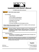
If this clearance ex-
ceeds 1", baffles
must be added to
prevent air by-pass
Baffle required to prevent trapping of hot air above refrigerator
Condenser
(source of
rejected heat)
Absorber
(source of
rejected heat)
When more than 1' clearance is required and/or roof jack is
installed inboard
Angle of baffle tilt not to exceed 45'
Not mandatory but recommended
for performance improvement
Greater than 1"
Add baffle within
1/4" to coils
Space above refrigerator baffled from point 'A" to point "8". Baffle bit must
not exceed 45'. Space at rear is baffled to improve draft through coils.
Roof Jack opening centered
over condenser (front to rear
of vehicle)
Figure 2 - Baffles Required at Rear
Construction Requirements
The optimum installation is illustrated in Figures 1,
3, 5, and 8 where clearances are minimum and the
roof jack is exactly centered over the refrigerator's
condenser. Not all coach construction will accommo-
date the optimum construction, so Figures 2 and 4
show optional installations which are permitted by the
certification.
Clearance at Rear
Figure 1 illustrates an installation where there is no
more than 1 inch clearance at the rear of the refrig-
erator. This is best for maximum efficiency.
Figure 2 illustrates an installation with more than 1
inch at the rear. The baffles are required to block off
by-pass air and still obtain good cooling efficiency.
Ventilation Above Refrigerator
The construction of Figure 3 achieves the best re-
sults where the roof opening is aligned with the con-
denser. Figure 4 illustrates an optional condition
where the roof opening is more inboard than the rear
of the refrigerator. This opening position is permitted,
provided a baffle is provided between Point A (in-
board edge of roof opening) and Point B (back edge
of refrigerator cabinet). The tilt angle (as indicated)
must not
exceed 45 degrees.
Figure 5 indicates the requirement to center the roof
jack opening over the condenser (front to rear of ve-
hicle). No options to this location are permitted.
Figure 3 - Roof Jack Above Condenser
Figure 4 - Roof Jack Inboard from Condenser
Figure 5 - Roof Jack Centered
(Front to Rear of Vehicle\
5

Side baffle should be in line
with top baffle at point "C"
(should be to rear of refrig-
erator cabinet)
The space requires a
baffle as shown between
points "A" & "B"
Top baffles & side baffles line
up at rear of refrigerator
(Point B directly
below Point C)
The space at side of refrig-
erator is completely blociced
off (blocking material could
be paneling, fiberglass baits,
etc.)
Side Blockage
A good installation requires a
minimum amount of side clear-
ance. Figure 6 illustrates the re-
quirement to allow no more
than 1/2 inch clearance on
either side of the refrigerator.
This minimum clearance can be
provided by built-in panels, fi-
berglass batts, or other types of
baffles. No options are permitted.
Rear View of Refrigerator
0
'0
0
0
0
0
4=1.,
0
0
0
0
0
0
0
00
0• Best
0
0
0" Best
1/2' maximum
0
0
1/2' maximum
allowable
'0'
r
0
allowable
0
0
0
0
0
0
0
0
0
0
0
0
0
0
0
0
0
0
0
0
0
0
0
0
0
0
0
Figure 6 - Maintain a Minimum Side Clearance
Figure 7 -
Incorrect
Alignment of Side Baffles
Figure 7 illustrates an
unap-
proved
installation where the
side baffle is not aligned with the
top baffle; consequently hot air
can fill above the refrigerator.
Figure 8 shows an approved
side baffle, aligned with the top
baffle. The rising hot air is car-
ried off and does not become
trapped above the refrigerator.
Figure 8 - Correct Alignment of Side Baffles
6

INSTALLATION INSTRUCTIONS
Certification and Code Requirements
The refrigerators described herein are certified un-
der the latest edition of ANSI 221.19 Standards by
the American Gas Association for installation in mo-
bile home or recreational vehicle and approval by the
Canadian Gas Association.
Installation of the refrigerator described herein must
conform to the Manufactured Home Construction and
Safety Standard, Title 24 CFR, Part 3280 [formerly
the Federal Standard for Mobile Home Construction
and Safety, Title 24 (Part 280), 1975].
Installation must be made in accordance with these
instructions in order for the certifications to be held
valid and the factory warranty to remain in effect.
United States installations must conform with the
latest editions of the following, as applicable:
a.
Local codes or, in the absence of local codes,
the National Fuel Gas Code, ANSI Z223.1.
b.
Local codes or, in the absence of local codes, the
Standard for Recreational Vehicles, ANSI A119.2.
The appliance must not be installed directly on car-
peting. Carpeting must be protected by a metal or
wood panel beneath the appliance which extends at
least the full width and depth of the appliance.
For installations requiring an electric outlet which is
energized by an external power source, the refrigera-
tor must be electrically grounded in accordance with
the latest edition of the National Electric Code.
ANSI/NFPA No. 70.
Canadian Installations must conform with the follow-
ing, as applicable:
1.
Local codes or, in the absence of local codes,
the current CAN 1-B149.2 Installation Code for
Propane Burning Appliances and Equipment.
2.
Current CSA Z240.4 Gas Equipped Recrea-
tional Vehicles and Mobile Housing or the cur-
rent CSA Z240.4.2 Installation Requirements for
Propane Appliances and Equipment in Recrea-
tional Vehicles.
3.
Current CSA Z240.6.2/C22.2 No. 148 Electrical
Requirements for Recreational Vehicles.
4.
When installed, the appliance must be electri-
cally grounded in accordance with the current
CANADIAN ELECTRICAL CODE C22.2
PARTS 1 and 2.
The refrigerator, designed and certified for built-in
•nstallation, requires opening dimensions as specified
in TABLE 2.
TABLE 2
REFRIGERATOR CUT-OUT OPENINGS (INCHES)
Model
Height
Width
Depth
662, 663
52 7/8
23 1/2
24
682, 683
59 7/8
23 1/2
24
Lower Flange Installation
The lower flange is shipped as a loose part to pre-
vent damage during shipment. The part is to be at-
tached after the refrigerator is set into the cut-out
opening. (See Figure 12)
A
WARNING
THE LOWER FLANGE CANNOT BE OMITTED
SINCE IT IS A PART OF THE COMBUSTION SEAL.
FAILURE TO MAINTAIN THIS SEAL COULD AL-
LOW EXHAUST FUMES INTO LIVING QUARTERS.
INHALING EXHAUST FUMES COULD CAUSE DIZZI-
NESS, NAUSEA, OR IN EXTREME CASES, DEATH.
1. Install the lower flange by maneuvering it un-
der and behind the bottom hinge plate, as
shown in Figure 9 (the hinge will be located
on either the right or left side, depending on
door swing preference).
Figure 9
2.
Once the lower flange is slipped around the
hinge, the part will swing into place as shown in
Figure 10.
3.
Secure the flange with screws provided. (Fig. 10)
Figure 10
7

Figure 11 - Rear View
LOWER FLANGE
(SEE FIGURES
9 AND 10)
BEFORE INSTALLING THE REFRIGERATOR, INSPECT
THE FACTORY INSTALLED SEAL STRIPS TO INSURE
THEY ARE IN PLACE CONTINUOUSLY AROUND THE
MOUNTING FLANGES.
Securing Refrigerator
After the refrigerator is mounted in place (insuring a
combustion seal at the front mounting flange), the
unit can be secured by screws through the mounting
Gas Connection
A
WARNING
flange and hole(s) provided at floor level in the rear
USE EXTREME CAUTION WHEN WORKING ON
(See Figure 11). Caps are provided to cover the OR NEAR A PROPANE GAS SYSTEM. DO NOT
mounting flange holes. SMOKE OR USE AN OPEN FLAME NEAR A PRO-
PANE GAS SYSTEM. LEAKING PROPANE GAS
CAN CAUSE AN EXPLOSION AND RESULT IN SE-
VERE PERSONAL INJURY OR DEATH.
When connecting the gas supply line to the refrig-
erator, use tubing and fittings that comply with local,
state, or national codes governing size and type. All
flexible metal connectors used must comply with the
provisions of the current Standard CAN1-6.10, MET-
AL CONNECTORS FOR GAS APPLIANCES. The
gas connection fitting is located at the inlet to the gas
valve (See Figure 13) and is a 3/8 SAE (UNF 5/8"-
18) male flare connection. Care must be taken when
final tightening of the tubing nut is done that the fit-
ting is held securely. Access to this fitting is through
the lower vent door.
Seal strips, provided with the refrigerator, must be
in position behind the mounting flange after the refrig-
erator is installed in the wall encbsure (See Figure 12).
Figure 12 - Location of Seals
A
WARNING
A
CAUTION
USE TWO WRENCHES WHEN TIGHTENING OR
UNTIGHTENING GAS INLET FITTING. FAILURE
TO USE TWO WRENCHES COULD OVER STRESS
TUBING AND CREATE GAS LEAKS.
The gas line should be routed in a manner to limit
the possibility of vibration or abrasion. It is recom-
mended that the gas supply line enter the combus-
tion chamber through the floor which supports the re-
frigerator. The hole size through which the gas line
enters should be of sufficient size that adequate
clearance is maintained. Once the gas line is in-
stalled a rubber type sealant should be applied
around the line at the point it enters the refrigerator
area. This will minimize abrasion, vibration, and
serve as a barrier from external moisture.
Once the gas line has been connected, ALL CON-
NECTIONS must be thoroughly checked for possible
leaks with a soap suds solution. DO NOT TEST FOR
LEAKS WITH AN OPEN FLAME.
A
CAUTION
THE SEAL MUST BE CONTINUOUS BETWEEN
THE REFRIGERATOR MOUNTING FLANGE AND
WALL TO ASSURE COMBUSTION SEAL. FAILURE DO NOT ALLOW LEAK DETECTION SOLUTIONS TO
TO MAINTAIN THIS SEAL COULD ALLOW EX- COME INTO CONTACT WITH ELECTRICAL COM-
HAUST FUMES INTO LIVING QUARTERS. INHAL- PONENTS. MANY SUCH LIQUIDS ARE ELECTRI-
ING EXHAUST FUMES COULD CAUSE DIZZI- CALLY CONDUCTIVE WHICH CAN CAUSE ELEC-
NESS, NAUSEA, OR IN EXTREME CASES, DEATH. TRICAL SHORTS AND IN SOME CASES, FIRES.
8

A
WARNING
DO NOT REMOVE OR CUT OFF GROUNDING
PRONG FROM AC CORD. ABSENCE OF PROPER
GROUNDING COULD CAUSE SEVERE ELECTRI-
CAL SHOCK OR DEATH WHEN TOUCHING MET-
AL PARTS OF THE REFRIGERATOR.
12 Volts DC Connection
All operating modes require a 12 volt DC supply
(even when AC or GAS modes are selected, a 12
volt DC control is required to maintain the control cir-
cuit functions). The DC lead connections
(1/4"
male
If compressed air is used for leak testing, the pres-
proximately 12" from the floor (See Figure 11). This
sure must not exceed 1/2 psig (3.4kPa).
allows easy accessibility through the vent door. The
The appliance and its individual shutoff valve (See
cord must be routed so as not to come in contact
Figure 13) must be disconnected from the gas supply
with the burner cover, flue pipe, or any other compo-
piping system during any pressure testing of that
nent that could damage the cord insulation. EXTEN-
system at test pressures in excess of 1/2 psig (14 SION CORDS ARE NOT RECOMMENDED.
inches Water Column).
Figure 13 - Gas & DC Supply Connections
The appliance must be isolated from the gas supply
quick connects) are at terminals located on the
piping system by closing its individual manual shutoff
Power supply at the rear of the refrigerator (See
Fig-
valve during any pressure testing of the gas supply
ure 13). One connection (J4) is marked positive (+)
piping system at test pressures less than or equal to
and the other (J3) negative (-). Correct polarity must
1/2 psig (14 inches Water Column).
be observed when connecting to the DC supply. The
After placing the appliance in operation, the gas
DC supply must be fused and must be a two wire sys-
safety shutoff device must be tested, by disconnecting
tern since the certification does not allow the refrigera-
the electrode wire to the ignition module (See Figure
for chassis to be used as the return leg of the circuit.
14). In not more than 20 seconds, the flame should
The distance the current must travel from the bat-
go out, indicating the safety valve is operational.
tery to the refrigerator dictates the AWG wire size to
be used. Should the wire be too small for the distance,
a voltage drop will result. In the case of 3-Way models,
the voltage drop affects the wattage output of the sys-
•
tern heater and resultant refrigerator performance. Rec-
ommended wire and fuse sizes are shown below.
TABLE 3
12 VOLT SUPPLY WIRING & FUSE SIZE
662, 682
663, 683
min. wire max. fuse min. wire max. fuse
size
size
size
size
0 - 20' 18 AWG 6 Amp 10 AWG 30 Amp
Figure 14 - Location of Electrode Wire
Electrical Connection
120 Volts AC Connection
This refrigerator is equipped with a three prong plug
for protection against shock hazard and must be con-
12 Volts DC Operation (3
-
Way Models Only)
netted into a recognized three prong attachment re-
ceptacle. The free length of cord is 24" and therefore
The refrigerator receives its power from the vehi-
is recommended that the receptacle be located to the
cle's 12 volt system, which in most cases is an auxil-
left side of the refrigerator (viewed from rear) and ap-
iary (house) battery. In some cases, it may be the
over 20'
18 AWG
6 Amp 8 AWG 40 Amp
If a wire size is installed which is larger than the
minimum size indicated in the table, it must be fused
in accordance with the requirements of the R.V.I.A.
A119.2 standard or local governing codes.
9

engine's battery. The battery source is not only fur-
Refrigerator Check Out
nishing the power for the refrigerator's DC mode, but
it is also supplying the demands for the other compo-
should the installation is complete, the refrigerator
s
d be checked out in both gas and electric op-
nents in the coach. For this reason, the refrigerator's
eration. Both gas and electric supplies must be con-
DC circuit is designed to be as energy conserving as
possible with the resulting cooling power somewhat
nected
.
and within specifications on the front page of
less than the gas and AC modes.
this manual. Refer to pages 15 and 16 for layout of
Mode Control Panel. Check functions as follows:
Set NORMAL-STORAGE-HIGH HUMIDITY switch
IMPORTANT INFORMATION ON 12 VOLT
to HIGH HUMIDITY; set thermostat to COLDEST.
DC OPERATION (3-Way Models Only)
On 3-Way models, set DC OFF/DC ON switch to
DC OFF.
The 12 volt DC mode is not designed for continu-
Set AUTO-OFF-GAS to AUTO. The Mode Control
ous DC operation - only for short "in transit" periods
panel should display AC indicating 120 volts AC.
when gas or AC sources are not available.
Disconnect AC power. Mode Control panel should
Check the DC supply voltage at the refrigerator (not
now display GAS, indicating the system has automat-
at the battery) while the unit operates on DC mode.
ically switched to gas upon loss of AC power.
The voltage must not be less than the minimum of
Let the unit operate on gas for a few minutes to
11.5 v
o
t
ts
.
insure the flame does not lock out.
The 12 voltDC mode cannot be used for the initial
With the aid of a mirror (dental type mirror is best),
pull-down of the refrigerator compartment(s). The in-
observe the flame. The flame should be sharp blue
itial cooling operation must be done in either the
as indicated in Figure 28 with a stable burning ap-
GAS or AC modes. The refrigerator must be cooled
pearance. The flame should have no yellow constitu-
and stabilized before the DC operation is effective.
ent or appear erratic or unstable. The flame should
The following points regarding the DC operation
be centered into the flue tube without touching the
should be considered:
inner wall of the tube. See Figure 28.
a.
Operate the refrigerator in the DC mode only
Turn off gas supply at refrigerator's manual valve
in periods when AC or GAS operation is un-
(See Figure 11). After about 20 seconds the red X on
available.
the Mode Control panel will indicate loss of flame.
b.
The DC operation is designed to operate during
Turn gas supply back on. The gas should remain
a short "hold over" period, such as a four (4) to
locked out. Switch AUTO-OFF-GAS to GAS. The gas
six (6) hour period while in transit. The refrig-
erator should not be switched to the DC mode
mode should be re-established indicated by LP on
if the food is not completely chilled.
the Mode Control panel.
c.
Good battery condition is essential when oper-
On 3-Way models, set DC OFF/DC ON switch
.
to
ating on DC. This implies an adequate recharg-
DC ON. The Mode Control panel should display DC in-
ing means which can handle the demands of
dicating operation in 12-volt DC mode. Also, the gas and
the refrigerator along with other loads.
AC functions will be disabled regardless of the AUTO-
d.
The wires from the battery to the refrigerator
OFF-GAS setting. Re-set the switch back to DC OFF.
must be of large enough size to handle the
Check the divider between the two doors; the divider
load. The connections must be clean, tight and
panel should feel warm after being on for a few min-
free from corrosion. If not, a resulting voltage
utes. Turn NORMAL-STORAGE-HIGH HUMIDITY to
drop will cause a decreased cooling capacity.
STORAGE. All functions, including Mode Control panel
and the interior cabinet light should be off. Then move
Hypot Tests
the switch to NORMAL. The refrigerator should return
to the operation indicated by the Mode Selector switch.
A successful Dielectric Strength test (Hypot test)
AN EXAMINATION OF THE VENT AND FLUE
has been conducted at the factory and the refrigera- SYSTEM SHOULD BE MADE TO INSURE THAT
for does not require an additional test. If Hypot tests
NOTHING IS OBSTRUCTING THE NORMAL FLOW
are to be conducted on other 12-volt DC circuits, the
OF COMBUSTION AND VENTING AIR. PAY PAR-
12-volt supply to the refrigerator must be discon-
TICULAR ATTENTION TO THE AREA ABOVE THE
nected to protect the sensitive electronic circuit. In
REFRIGERATOR TO GUARANTEE THAT FIBER-
addition, never contact the positive probe of the Hy-
GLASS OR OTHER MATERIALS DO NOT BLOCK
pot tester to the chassis or grounded members of the THE PASSAGE. THE REFRIGERATOR AREA
vehicle since damage could be introduced into the
MUST BE CLEAN AND FREE OF COMBUSTIBLE
electronics. Failure to observe these precautions
MATERIALS, GASOLINE, AND OTHER
FLAMMA-
voids the Warranty.
BLE VAPORS OR LIQUIDS.
10

!!
I
N—(B)
(A)
11
1
Decorative Door Panel Installation
Instructions for Reversing Door Swing
The Norcold refrigerator doors provide slots for in-
Your refrigerator is equipped with convertible door
serting decorative panels. Installation of the panels is
hinges. The hinging of the doors can be changed to
accomplished by removing the handle assembly, in-
the opposite side anytime you wish.
serting the decorative panel, and re-inserting the
handle assembly. This procedure applies to both
TOOLS REQUIRED
doors. (See Figure 15)
-
The frame slots are designed to accept panel thick-
Phillips Screwdriver Size #2
ness up to 3/16" maximum.
Two Slotted Screwdrivers
TABLE 4
PANEL DIMENSIONS
662, 663
682, 683
Upper Door 19 11/16" x 16"
19 11/16" x 16"
Lower Door 19 11/16" x 32 1/4" 19 11/16" x 39 1/4"
INSTRUCTIONS
1.
Prepare panel by cutting to size indicated in ac-
companying chart. (See TABLE 4)
2.
Remove handle assembly (A) by removing four
screws (B). (See Figure 15)
3.
Slide panel into frame slots.
4.
Replace the handle assembly.
Figure 15
Figure 16
REMOVING THE DOORS
1.
Remove all items of food, juices, etc., from the
doors. Remove the juice rack and storage bins.
Cbse both doors before removing hinge pins.
(See Figure 24)
2.
Remove the top hinge pin using one of the slot-
ted screwdrivers. Remove the center hinge pin
(both pieces) using the two slotted screwdriv-
ers; one on each end of the pin. Lastly, remove
the bottom hinge pin. Be sure to save the pins
for reassembly later. (See Figure 23)
3.
Remove the upper door by opening the door
slightly and pulling the bottom of the door away
from the refrigerator. Allow enough room to
slide the door down off of the upper hinge pin
shoulder. (See Figure 17)
Figure 17
4.
Remove the lower door by opening it slightly
and pulling the top of the door away from the
refrigerator. Allow enough room so the door can
be lifted up and off of the bottom hinge pin
shoulder (See Figure 18). Be sure to save the
hinge plates along with the spacer used in the
middle hinge bracket, for reassembly later. (See
Figures 23A, 23B, and 23C)
11

hole plugs from each of the corresponding
holes on the opposite side of the refrigerator.
Relocate them in the two holes just exposed by
the removal of the latches. Using the two
screws, attach each latch in the new position so
the tab points towards the opposite side of the
refrigerator. Do not tighten screws completely.
(See Figure 20)
Figure 18
REMOVING AND RELOCATING THE HINGE
BRACKETS
5. Remove the middle hinge bracket by using the
#2 Phillips screwdriver and taking out the three
screws holding it in place. Next, with fingernails,
lift and remove the three hole plugs on the op-
posite side corresponding to the center hinge
Figure 20
location. Relocate them in the holes just ex-
posed by the removal of the hinge bracket. Us-
ing the same screws, attach the hinge bracket
to the refrigerator where the hole plugs pre-
viously were. Do not tighten screws completely.
(See Figure 19)
Figure 19
6.
Remove the top hinge bracket and reposition it
in the opposite bottom corner. Use the same
Figure 21
technique as outlined in Step #5.
7.
Remove the bottom hinge bracket and reposi-
tion it in the opposite top corner. Use the same
technique as outlined in Step #5.
RELOCATING THE TRAVEL LATCHES
8.
Remove both travel latches by taking out the
two screws holding each to the refrigerator. Use
the #2 Phillips screwdriver. Remove the two
9. Turn the door over so that the end previously at
the bottom is now at the top. Relocate the bot-
tom of the door on the bottom hinge pin shoul-
der. Close door and align holes in top hinge
brackets. The magnetic gasket will hold the
door in place. Before reinstalling the top door,
check to insure that the spacer is in place. (See
Figures 21 and 23C)
10.
Reposition the upper door in a similar manner
as described in Step #9, except the top of the
door must be engaged into the hinge pin
shoulder before setting the door
in
place.
(See Figure 22)
11.
Starting at the top, replace the hinge pins using
the slotted screwdrivers as in the
removal pro-
cedure. Tighten all screws.
12

Figure 22
Figure 23
ALIGNMENT OF THE DOORS
12.
Align the upper door with the lower so that
there is a parallel gap between the doors and
around the frame. Adjust the doors to the cabi-
net so the gaskets seal but do not bind. Tighten
the screws holding the hinge brackets in place.
13.
Door Seal: The door seal can be checked by
closing the door on a 1" x 6" strip of paper. A
slight drag should be noticed when the paper is
pulled out from between the gasket and the
cabinet. Repeat the process around all four
sides of the door. If the door does not seal
properly, readjust the hinge brackets.
14.
Position the travel latches so that they secure
the doors when closed but does not prevent the
doors from closing properly. Tighten the two
screws in each travel latch.
15.
Replace the juice rack and storage bins into
the door. Make sure that the milk bins (wider
storage bins) are installed in the lowest door
position.
13

NOTES
14

IAC
1
AUTO OFF GAS
IP
1
I
ELEC CHECK GAS
COLD COLDEST
ELEC
OPERATION
1.
Move thermostat to COLDEST position. Set
AUTO-OFF-GAS switch to AUTO.
2.
If 120 volts is active, Mode Control panel will
display AC, indicating refrigerator is operating in
120 volt AC mode.
3.
If 120 volts AC is inactive (power failure, dis-
connected, etc.), Mode Control panel will dis-
play LP, indicating refrigerator has automatically
switched to LP gas mode.
4.
If Mode Control panel displays LP and a red X
continuously, the refrigerator has failed to ignite
burner on gas mode. Restart gas operation
by
DO NOT CONTINUE TO RESET GAS SWITCH IF
moving AUTO-OFF-GAS switch to OFF and CHECK INDICATION CONTINUES TO DISPLAY
back to AUTO (See steps 3, 4, and 5 under AFTER SEVERAL TRIES. A GAS BUILD-UP MAY
Gas Mode.). Note: Unit operation will automat-
OCCUR IN THE BURNER AREA AND RESULT IN
ically return to AC when 120 volts AC is restored, A FLASH BACK WHICH MAY CAUSE PERSONAL
even if the unit is locked out on gas operation.
INJURY.
5.
Move thermostat to desired setting, usually a
mid setting.
Shut Down Instructions - Gas or Electric
Start Up Instructions - Auto Mode
3.
After 10 seconds, the burner should be ignited
and operating normally.
4.
On the initial refrigerator start-up, it may take
longer than 10 seconds to allow air to be
purged from the gas line. If gas does not ig-
nite within 20 seconds, valve will automat-
ically shut off and the red X will be displayed
at the CHECK position.
5.
To restart when the X is displayed, move
AUTO-OFF-GAS switch to OFF position then
return switch to the GAS position.
A
CAUTION
AUTO OFF GAS
I
ELEC CHECK GAS
COLD COLDEST
u.
I
MEIN
GAS
OPERATION
AUTO OFF GAS
E
t
a
k
=
t
ELEC CHECK GAS
COLD COLDEST
NO
OPERATION
LIGHTING INSTRUCTIONS
PRELIMINARY REQUIREMENTS:
a) 12 volts must be present for any selected mode of operation.
b) The NORMAL-STORAGE-HIGH HUMIDITY switch must be set to NORMAL or HIGH HUMIDITY.
(2-Way Models)
Start Up Instructions - Gas Mode
1.
Move thermostat to COLDEST. Set AUTO-
OFF-GAS switch to GAS.
2.
Mode Control panel will display LP, indicating
LP gas mode (If LP is not displayed, check for
loss of DC supply voltage.). Initially, the red X
will be displayed for about 2 seconds; after
which, sparking will start at the burner and the
red X goes off.
Short Duration: Set AUTO-OFF-GAS switch to OFF.
Long Duration: Set NORMAL-STORAGE-HIGH HU-
MIDITY switch (located on divider be-
tween the two doors) to STORAGE.
15

84- 8,9 AUTO OFF GAS ELEC CHECK GAS COLD COLDEST
AC
OPERATION
.1.±1
milc5±1
I AC
1
OFF 82
AUTO OFF GAS ELEC CHECK GAS COLD COLDEST
fy
NO
OPERATION
(3-Way Models)
4.
On the initial refrigerator start-up, it may take
longer than 10 seconds to allow air to be purged
from the gas line. If gas does not ignite within 20
seconds, valve will automatically shut off and the
red X will be displayed at the CHECK position.
5.
To restart when the X is displayed, move
AUTO-OFF-GAS switch to OFF position then
return switch to the GAS position.
Start Up Instructions - Auto Mode
A
CAUTION
82
AUTO OFT GAS ELEC CHECK GAS COLD COLDEST
DC
Eta. 1±.111±1
I DC
OPER
ATION
1.
Move thermostat to COLDEST position. Set
AUTO-OFF-GAS switch to AUTO. Set DC
OFF/DC ON to DC OFF.
2.
If 120 volts is active, Mode Control panel will
display AC, indicating refrigerator is operating in
120 volt AC mode.
3.
If 120 volts AC is inactive (power failure, dis-
connected, etc.), Mode Control panel will dis-
play LP, indicating refrigerator has automatically
DO NOT CONTINUE TO RESET GAS SWITCH
switched to LP gas mode.
IF CHECK INDICATION CONTINUES TO DIS-
4.
If Mode Control panel displays LP and a red X
PLAY AFTER SEVERAL TRIES. A GAS BUILD-
continuously, the refrigerator has failed to ignite
UP MAY OCCUR IN THE BURNER AREA AND
burner on gas mode. Restart gas operation by RESULT IN A FLASH BACK WHICH MAY
moving AUTO-OFF-GAS switch to OFF and CAUSE PERSONAL INJURY.
back to AUTO (See steps 3, 4, and 5 under
Gas Mode.). Note: Unit operation will automat-
ically return to AC when 120 volts AC is restored,
DC Mode
even if the unit is locked out on gas operation.
5.
Move thermostat to desired setting, usually a
mid setting.
Start Up Instructions - Gas Mode
8F%
82
AUTO OFF GAS ELEC CHECK GAS COLD COLDEST
GAS
sk±1
'
1
OPERATION
1.
Move thermostat to COLDEST. Set AUTO-
OFF-GAS switch to GAS. Set DC OFF/DC ON
to DC OFF.
2.
Mode Control panel will display LP, indicating
LP gas mode (If LP is not displayed, check for
loss of DC supply voltage.). Initially, the red X
will be displayed for about 2 seconds; after
which, sparking will start at the burner and the
red X goes off.
3.
After 10 seconds, the burner should be ignited
and operating normally.
1.
Move thermostat to COLDEST position.
2.
Set DC OFF/DC ON switch to DC ON. (DC ON
will override the AUTO-OFF-GAS switch.)
3.
Mode Control panel will display DC, indicating
operation in DC mode.
Shut Down Instructions - All Modes
Short Duration: Set AUTO-OFF-GAS switch to OFF.
Set DC OFF/DC ON switch to
DC OFF.
Long Duration: Set NORMAL-STORAGE-HIGH HU-
MIDITY switch (located on divider be-
tween the two doors) to STORAGE.
16

Door in closed position
(Door Gasket Sealed)
OPERATING AND USER INSTRUCTIONS
Operation in Transit
While the refrigerator should be level when the ve-
hicle is stopped, performance during transit is not
normally affected.
Door Latch
The refrigerator's built-in door latch prevents the
door from flying open during transit. There are no
chains or slides to remember to actuate when the
THIS APPLIANCE HAS BEEN DESIGNED FOR
vehicle starts moving (See Figure 25). Always close
STORAGE OF FOODS, STORAGE OF FROZEN
the door to the sealed position (audible click) to pre-
FOODS AND MAKING ICE WHEN INSTALLED AS vent cooling loss and heavy frost.
Norcold cannot accept responsibility for re-
pairs, adjustment, or maintenance performed
by other than a qualified dealer or service
center. Resultant costs or related consequen-
tial problems cannot be assumed by Norcold.
The nearest qualified service location can be
furnished by a) your dealer, b) the qualified
service center list supplied with the refrigera-
tor, or c) contacting Norcold.
DIRECTED BY THIS MANUAL.
Location of Controls
Figure 24 illustrates the locations of the refrigera-
tor's operating controls. The Mode Control panel is
located above the upper door and includes the
thermostat for controlling the interior temperatures,
the switches which select the operating mode, and
an area which continuously displays the selected op-
erating mode. On the divider panel, located between
the two doors, is the High Humidity and Storage switch.
See following paragraphs for a description. The light
switch, which is located in this area, automatically ac-
tivates the cabinet light when the lower door opens.
Figure 24
Leveling
Norcold refrigerators do not require critical leveling
such as required by other absorption type refrigerators.
Normal vehicle leveling to provide comfort for the
occupants is satisfactory for refrigerator operation.
This will be well within the refrigerator's operation
limits of 3 degrees off-level side to side and 6 de-
grees off-level front to back.
Figure 25
Door Latch in Sealed Position
Mode Selector
This refrigerator is equipped with Norcold's exclu-
sive Mode Selector. A description of each of these
selections follows:
AUTO: The refrigerator will operate on 120 volts
AC so long as AC power is available to the
refrigerator. If AC power is lost (or discon-
nected), the Selector will automatically
switch to gas operation. As soon as AC
power is restored, the Selector automat-
ically switches back to AC operation (The
user does not have to manually switch the
refrigerator back to AC). When the opera-
tion is automatically switched to gas, the
burner will ignite and continue to operate
the refrigerator at the same thermostat set-
ting as set for AC power.
Note: If a 3-Way model, DC ON/DC OFF switch
must be set at DC OFF.
GAS: This selection allows the refrigerator to op-
erate on LP gas only. It will not automat-
ically switch modes regardless of whether
AC power is connected. If the flame is lost
17

Additional Information on Controls
A
CAUTION
NEVER ALLOW WATER TO BE SPRAYED DI-
RECTLY ON ELECTRICAL CONTROLS LOCATED
BEHIND THE INLET VENT DOOR. ELECTRICAL
DAMAGE OR FIRES COULD RESULT.
Figure 26
Mode Display
The lighted display area provides a continuous indi-
cation of the refrigerator's operating mode. A descrip-
tion of each indication is as follows:
AC: Indicates 120 volt AC is connected and op-
erating in that mode while the Mode Selec-
tor switch is set at AUTO.
LP: Indicates the gas burner is operating nor-
mally in the LP gas mode. However, if a
red X is also displayed, the gas burner is
off and the refrigerator is locked out in the
gas mode. As a safety precaution, the
Mode Selector switch must be manually re-
set. See Lighting Instructions on page 15
(2-Way) or page 16 (3-Way).
X: Indicates the gas burner is off in the gas
mode. See explanation in the preceding
paragraph.
DC: (3-WAY Models Only) Indicates refrigerator
is operating on 12 volts DC with the Mode
Selector set at DC ON.
(LP bottle empty, etc), the operation locks
position. This position shuts off all DC power includ-
out and must be manually reset.
ing the light and humidity heater and allows the re-
Note: If a 3-Way model, DC ON/DC OFF switch
frigerator door to be left open for airing without
must be set at DC OFF.
chance of battery drain during storage. (See "Infor-
12 VOLT DC (3-WAY models): Selecting DC op-
mation Regarding Battery Drain" below.) The "STOR-
eration overrides all other operating modes
AGE" position also prevents refrigerator operation,
(all three settings of the AUTO-OFF-GAS
regardless of where the Mode Selector is set.
switch). If DC power is lost, the refrigerator
remains off until the DC per is restored. It
does not require a manual restart procedure.
1.
Be attentive when the outer coach surface
is
being hosed down to avoid wetting the refrig-
Thermostat
erator controls.
2.
The User should be aware that 12 volts DC is
The thermostat on the Norcold refrigerator con-
required during all operating modes (AC,
trols both the gas and electric operation thereby
GAS, DC). 12 volts is necessary to energize
eliminating the necessity of resetting each time a
the cabinet light, humidity heater and the
different energy source is employed. After the in-
mode display area.
itial start-up, the thermostat should be moved from
3. This Norcold refrigerator is equipped with
"COLDEST" to the desired temperature setting,
electronic ignition (no pilot flame). It provides
usually about mid setting.
automatic gas ignition on start-up, automatic
re-ignition in case of flame blowout and elec-
High Humidity
-
Storage Switch
trical signal to warn of flame failure (red X on
mode display).
Pressing this switch (Figure 26) to "HIGH HUMID-
ITY" will keep the surface between the door openings
Information Regarding Battery Drain
dry during high humidity conditions. The switch
should be left in the "NORMAL OPERATION" posi-
As indicated, a 12 volt DC source is required for
tion unless condensation is observed in this area.
operation on gas to provide features of automatic ig-
Both NORMAL and HIGH HUMIDITY positions al-
nition. The current draw is less than 500 milliamps. If
low the cabinet light to activate when the lower door
the humidity heater is also energized, this adds 240
is opened.
milliamps for a total less than 740 milliamps (.74
When your RV is being stored for the winter, this
amps). This indicates that the drain on the battery is
switch should be placed in the "STORAGE" (light off)
very low and has little effect on "battery run down"
18

Figure 27
unless these switches are left on for long periods of
time on a battery with no means of recharging.
During AC operation, 12 volt DC is required to oper-
ate the interior light, humidity heater, the mode dis-
play, and electronic thermostat.
On 3-Way Models, the DC operation draws approxi-
mately 14.5 amps at 12 volts or 16 amps at 14 volts.
The DC voltage should be checked while operating
in the DC mode. The voltage at the refrigerator
should never drop below 11.5 volts.
Battery drain should also be considered during
times when the refrigerator is stored, defrosted, or
occasions when the door is left open. The interior
light will draw 600 milliamps and the humidity heater,
if left on, draws 240 milliamps for a possible current
draw of 840 milliamps (.84 amps). In this case, the
NORMAL-STORAGE-HIGH HUMIDITY switch should
be set to the "STORAGE" position (See section on
"High Humidity - Storage").
Except for DC operation (3-Way Models) it is evi-
dent that the 12 volt demand is quite low; neverthe-
less, the refrigerator should not be operated for long
periods of time from a battery only, without a means
of recharge (through alternator or converter).
The Freezer Compartment
Door Sealing
To maintain cooling efficiency and prevent exces-
sive frost build-up, the doors must seal completely
around the entire length of the door gasket. Frequent
frost build-up or reduced cooling are indications of air
leaks. To check for complete door sealing, lay a long
strip of paper (or a dollar bill) across the flange,
against which the gasket seals; then close the door.
A frictional drag should be felt upon withdrawing the
paper. Repeat in several places all around the door.
If the paper feels loose, the gasket is not sealing.
Contact your dealer or Service Center.
A
CAUTION
DO NOT USE UNDUE FORCE OR JERKING AC-
TION WHEN OPENING THE REFRIGERATOR
DOOR. AIR TEMPERATURE DIFFERENCES CAN
CAUSE A PARTIAL VACUUM WITHIN THE CABI-
NET REQUIRING A FIRM BUT STEADY FORCE
TO OPEN THE DOOR. A SUDDEN JERK COULD
CAUSE DOOR DAMAGE OR PERSONAL INJURY.
Defrosting the Refrigerator
This compartment is not designed for the quick
After a period of operation, it is normal for frost to
freezing of food, but designed to retain food in a fro-
gradually accumulate on the freezer plate and the
zen state. Foods purchased for storage in the freezer
cooling fins, thereby impairing cooling efficiency.
compartment should be frozen when purchased to
To defrost the refrigerator, remove all food, then move
reduce the load on the refrigerator system.
the NORMAL-STORAGE-HIGH HUMIDITY switch to
IMPORTANT: Ice trays must be placed on the
"STORAGE". Fill trays with hot water, placing them
bottom freezer surface when
in the freezer compartment. When all frost has
making ice.
melted, empty the drip tray (beneath the finned
Water will freeze more rapidly if the thermostat is at
evaporator) and wipe up the excess moisture with
it's coldest setting.
a clean cloth. Replace the drip tray (making sure
The freezer shelf (Figure 27) can be adjusted for
the drain is not clogged and the tray engages the
three different heights or can be removed for large
drain tube) and all the food. Place the refrigerator
back
packages. Do not place packages on ice trays
ack into operation. Set the thermostat to its cold
while water is freezing.
est setting for a few hours for maximum cooling
before returning it to its normal operation.
A
WARNING
NEVER BEND, DROP, DRILL, OR WELD THE
COOLING UNIT. DOING SO COULD CAUSE THE
UNIT TO RUPTURE, RELEASING DANGEROUS
CHEMICALS WHICH CAN CAUSE SEVERE
BURNS TO THE EYES OR SKIN.
Cleaning the Refrigerator
It is important to keep the cabinet clean to minimize
the possibility of food odor. The best time to clean
the cabinet is after defrosting the refrigerator. Re-
19
/