Page is loading ...

First of all, let me just say “Thank You!” for choosing the Tower Hobbies
®
System 3000
™
4-TH! All of us here at Tower
Hobbies are very pleased with the 4-TH, because we feel it offers you, the Tower Hobbies customer, one of the very best values
available in an airplane system.
The 4-TH offers 4-channel control, enough for trainer and many sport models. As an FM narrow-band system, it's far less
vulnerable to interference than AM radios. The narrow-band transmitter and dual-conversion receiver enhance strong control
by filtering and boosting the signal. Combined, they'll provide you with smooth, glitch-free operation even in today's “noisiest”
radio environments.
Those are big pluses, but we went even further to make the 4-TH the most complete
4-channel radio we've ever offered. The case has been ergonomically designed to ensure a
more comfortable fit for your hands, allowing you many hours of flying enjoyment. You also
receive such advantages as a full set of NiCd batteries with charger, reversing switches for
all channels, improved trainer jack and more.
Packed with easy-to-use features and complete with a 1-year limited warranty, the
4-TH is a valuable investment toward superior model control. Congratulations on your
purchase and happy flying!
Sincerely,
Bruce R. Holecek
Founder and Chief Executive Officer,
Tower Hobbies
®
®
4-TH 4-CHANNEL FM RADIO CONTROL SYSTEM
INSTRUCTION MANUAL FOR R/C AIRPLANE USE
QUICK REFERENCE GUIDE
QUICK REFERENCE GUIDE
NOTE: This Quick Reference Guide is a condensed version of all
information given in this manual. We strongly recommend you
first read this entire manual before operating your 4-TH system
or your model.
1. Charge the transmitter and receiver batteries for 15 hours with
the included charger.
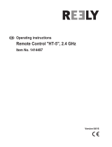
2. Connect servos, 4-cell battery pack and switch harness to the
receiver as shown at right.
3. Turn on the transmitter and then turn on the receiver
switch harness.
4. Center all four transmitter trim levers. Make sure all servos
operate according to transmitter stick movements.
5. Turn off the system, receiver first, then transmitter.
6. Wrap the receiver and receiver battery in foam rubber
(HCAQ1000 or HCAQ1050) for protection from vibration and
hard landings.
7. Install the entire radio system into your model as shown in the
model's instruction manual (see receiver picture to the right
for proper channel usage).
8. If you need to reverse the direction in which a servo rotates, locate
the reversing switch for the desired channel on the bottom front
of the transmitter and slide it to the “REVERSE” position.
9. Range test the radio system prior to flight. With the transmitter
antenna collapsed, you should be able to smoothly control
movement of all control surfaces on your model from at least
100ft on the ground.
Receiver (Rx)
Transmitter (Tx)
Charge
Plug
Battery
Plug
Antenna
Throttle,
Rudder
Stick
Trainer
Switch
Elevator,
Aileron
Stick
Switch
Harness
Rudder
CH 4
Throttle
CH 3
Elevator
CH 2
Aileron
CH 1
™
Reversing Switches
Power Switch
Elevator Trim
Aileron Trim
Throttle Trim
Rudder Trim
Crystal Holder

BEFORE INS
BEFORE INS
T
T
ALLA
ALLA
TION
TION
The rechargeable batteries inside of the Tx and the Rx pack must be fully charged prior to use. Plug the supplied charger into
a 110V AC wall outlet. Connect the charger's output leads to the Rx pack and the charge jack located on the side of the Tx
(make sure the power switch is OFF). The corresponding LEDs will illuminate on the charger when a good electrical
connection is made with each battery. When charging is complete, disconnect the charge leads from the batteries and
disconnect the charger from the wall.
• Do not fly simultaneously on a frequency that is already
being used in your area. Doing so could cause unwanted
interference, a crash and possibly bodily harm.
• Always attach the proper frequency flag to the
transmitter’s (Tx's) antenna when flying. This alerts others
at the flying field as to which frequency you are using.
• Do not fly in the rain or at night. Water can permanently
damage many of the components in the radio system,
possibly causing loss of control and a crash.
• Only fly at designated R/C flying fields. Fly at safe
distances away from other people, objects in the air,
buildings, electrical lines, or any other object which
could possibly impede safe flying. Failure to do so could
cause a crash and possibly bodily harm and physical
damage to other property.
• Extend the Tx and recevier (Rx) antennas to maximum
length when flying. Make sure the Tx antenna is threaded
into the Tx tightly. Always test the radio system before
use. Make sure the operation of each channel in the radio
is in the proper direction. If a channel does not accurately
respond according to Tx stick input, do NOT fly the
plane. Check for and correct improperly functioning
equipment before use. Failure to ensure proper radio
operation before flight could result in a crash.
• During flight preparations, be certain to place the Tx on
its back when on the ground, to prevent it from
accidentally falling over and inadvertently moving the
throttle stick to high speed.
• Do not allow fuel or oil on the plastic parts. Some plastics
may melt when exposed to such materials.
• BEFORE turning the Tx's power switch “ON”, adjust the
throttle stick to minimum speed position. After stopping the
engine turn “OFF” the Rx's power switch, then turn “OFF”
the Tx power switch. Failure to follow this order could
cause the engine to go to full throttle and cause an injury.
• Do not make adjustments to the radio system while the
engine is running unless absolutely necessary. Failure to
do so could cause the engine to accidentally go to high
speed and cause an injury.
• Always fully charge the Tx and Rx NiCd batteries before
each flight. Failure to do so could cause an inadvertent
power failure and a crash. Use the charger supplied with
this system. If using another charger, do not overcharge
the battery, as it could cause burns, fire, injury or other
equipment damage. Do not short circuit the NiCd battery
terminals, as arcing, overheating or fire could result.
• Do not leave the radio system, batteries, model airplane or
other modeling equipment within the reach of children.
• Do not overheat or throw the NiCd batteries into a fire.
Leaking electrolyte from the battery could cause injury,
such as burns or blindness. IN CASE OF EMERGENCY,
IMMEDIATELY FLUSH YOUR EYES, SKIN OR CLOTHES
WITH PLENTY OF WATER AND SEE A DOCTOR.
Recycle the battery when no longer in usable condition.
• Store the radio with all NiCd batteries in the discharged state
and be certain to fully charge the batteries just prior to use.
• Do not store the radio system in extreme heat (exceeding
104°F) or cold (below -14°F), in direct sunlight, in high
humidity, in high vibration environments or in dusty areas.
PREFLIGHT PREC
PREFLIGHT PREC
A
A
UTIONS
UTIONS
P
P
A
A
GE 2
GE 2
Please read this entire manual carefully and use your radio system safely.
Pay special attention to all precautions and warnings to ensure the safest operation.
WARNINGS

THE
THE
TRANSMITTER
TRANSMITTER
P
P
A
A
GE 3
GE 3
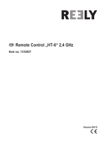
The 4-TH transmitter (Tx) is designed for mode-II operation.
Mode-II is commonly used throughout the U.S., where the
aileron and the elevator are controlled with the right stick and the
throttle and rudder are controlled with the left stick. Operation of
controls and their assigned channel numbers are as follows:
Aileron Control (CH1): When the aileron stick is moved to
the right, the right aileron is raised and the left aileron is
lowered and the plane banks to the right. When the aileron
stick is moved to the left, the ailerons move in the opposite
direction and the airplane banks left. To level the plane, the
aileron stick must be moved in the opposite direction and
back to center.
Elevator Control (CH2): When the elevator stick is pulled
back, the tail elevator is raised and the tail of the plane is
forced down, thus causing the plane to climb (UP operation).
When the elevator stick is pushed forward, the elevator is
lowered; the tail of the plane is forced up, thus causing the
plane to descend (DOWN operation).
Throttle Control (CH3): When the throttle stick is pulled
back, the engine throttle lever arm moves to the SLOW (low
speed) side. When the throttle stick is pushed forward, the
throttle lever arm moves to the HIGH (high speed) side.
Rudder Control (CH4): When the rudder stick is moved to the
right, the rudder moves to the right and the nose points to the
right, thus causing the plane to turn right. When the rudder
stick is moved to the left, the rudder moves to the left and the
nose points to the left, thus causing the plane to turn left.
During normal conditions, the range, or safe operating
distance from the Tx to the Rx is “line of sight”. This means
the 4-TH should maintain complete control any time you can
see your model. The 4-TH operates on the 72MHz frequency
band. There are 50 different channels available for this system
ranging from 72.010MHz (Ch11) through 72.990MHz
(Ch60). For safety reasons, you must always be aware of what
channel you are using so that no two radios in the same area
are EVER operating on the same frequency simultaneously.
Aileron
CH1
Rudder
CH4
Throttle
CH3
RIGHT
GIMBAL
Figure 1
LEFT
GIMBAL
Elevator
CH2
Trainer Switch
Aileron Trim
Servo Reversing
Switches
Power Switch
Elevator Trim
Rudder Trim
Throttle Trim
Charge Jack
Power LEDs
Over 9V: Both on
8.5V – 9.0V: Red on, green off
Under 8.5V: Red flashes, green off
Antenna
Trainer Jack
Battery Cover

S
S
TICK LEVER LENGTH
TICK LEVER LENGTH
ADJUS
ADJUS
TMENTS
TMENTS
The stick lengths can be adjusted to match different
preferences (see figure 2). Turn the stick head (A) counter-
clockwise and stick head (B) clockwise to unlock. Adjust the
length to your preference and lock in reverse order.
Stick
Head B
Stick
Head A
Figure 2
THE
THE
TRANSMITTER (C
TRANSMITTER (C
ONTINUED)
ONTINUED)
P
P
A
A
GE 4
GE 4
The rechargeable batteries inside the transmitter and the receiver
pack must be fully charged prior to use. Plug the charger into a
110V AC wall outlet. Next, connect the charger's output leads to
the Rx battery pack or switch harness and Tx charge jack. The
respective charger LEDs will illuminate as you connect the
charger to the batteries. Charge each battery for 15 hours. The
batteries may become warm as they charge. This is normal and a
good indication that the batteries are becoming fully charged.
NOTE: The Tx and Rx batteries should be charged the night
before each use. If the batteries have not been used for several
months, you may need to cycle them prior to use. Cycling is
the process of fully charging, then discharging, rechargeable
batteries to help maximize their charge capacity and run
time. To cycle a battery, charge it for 15 hours and then
discharge it by turning on the transmitter. The Tx's voltage
indicator should not drop into the red zone (with the antenna
extended) for 90 to 120 minutes. If it does, cycle the batteries
again. If the batteries still cause the voltage indicator to drop
in less than 90 minutes after repeated cycles, battery
replacement is recommended. The old batteries should be
disposed of at a recycling center.
TRAINER FUNCTIONS
TRAINER FUNCTIONS
The trainer function is a very effective way to teach others
how to fly. To use it, the special trainer cord (sold separately)
is necessary. The trainer cord comes in 2 configurations,
based on what transmitter is being used as a “Buddy Box”.
Configuration 1 can be connected to Tower 6FM, 4FM
and Futaba
®
SKYSPORT4, FF5, SKYSPORT6, 7U series, 8U
series and PCM1024Z series transmitters. The Tower trainer
cord TOWM6081 or the Futaba FUTM4420 may be used in
this configuration.
Configuration 2 can be connected to another Tower 4-TH
and the new Futaba 9C series transmitters. The Tower trainer
cord TOWM6082 or the Futaba FUTM4415 may be used in
this configuration.
OPERATING INSTRUCTIONS
Connect the student and instructor transmitters with the
trainer cord.
Instructor side:
Turn on the power switch and extend the antenna to its full
length. When the trainer switch is not pressed, the instructor
has control. When the spring-loaded trainer switch is pressed
and held, control of the airplane is transferred to the student.
Student side:
WARNING: Never turn on the student transmitter power
switch. Turning on the power switch will cause interference
and a crash. Set the student and instructor transmitter controls
to the same settings. For example, if the direction of operation
of any channel is reversed, control will be incorrect and the
plane will crash. All trim settings on the student Tx should
match that of the instructor Tx. The instructor’s Tx can only be
an FM (PPM) type transmitter. If the modulation method is
different, control is impossible.
Before training, it is important to follow these preflight checks:
1. Connect the appropriate trainer cord to the appropriate trainer
cord jack; they are located on the rear of the transmitters.
2. Turn off the instructor’s Tx and Rx switch harness in the
model. Caution: Do not turn on the student's Tx or
damage to the instructor's Tx will occur. The student's Tx
will receive its power from the instructor's Tx.
3. Set the trims and reversing switches on the student's Tx to
match the instructor's Tx.
4. Press and hold the trainer switch on the instructor's Tx. The
student should now be able to control the aircraft. Caution:
Make sure the student's Tx is properly controlling the
aircraft. Any difference in operation could cause loss of
control during flight.
5. Release the trainer switch in order to confirm that the
instructor's Tx has regained control of the model.
6. You are now ready to begin flight training.
Caution: Training should only begin if an experienced pilot is
controlling the instructor's transmitter. Failure to do so could
put yourself and others in the area at risk of injury or property
damage. To make your R/C modeling experience more
enjoyable, it is recommended that you get an experienced
instructor for your first flights. Experienced instructors can be
located at your local R/C club; some even offer training
programs and insured newcomer training. To locate a club in
your area, you can contact the national Academy of Model
Aeronautics (AMA), which has more than 2,500 chartered
clubs across the country. Please contact the AMA at:
Academy of Model Aeronautics
5151 East Memorial Drive
Muncie, IN 47302-9252
Tel: (800) 435-9262 Fax: (765)741-0057
http://www.modelaircraft.or g/
To Loosen:

Use the frequency flags that are supplied with your R/C
system so that other modelers at the flying field can identify
your channel number. Attach the flags to the base of the Tx
antenna as shown in figure 3.
Frequency board
Side A
Side B
Band Number Seal (after sticking)
Figure 3
FREQUENCY FLA
FREQUENCY FLA
G
G
P
P
A
A
GE 5
GE 5
SER
SER
V
V
O INS
O INS
T
T
ALLA
ALLA
TION
TION
All servos should be mounted as shown in the model's
instructions. Use the rubber grommets, screws and brass
eyelets supplied when mounting your servos (see figure 4).
Do NOT over-tighten the mounting screws. The servos should
be able to move slightly to compensate for engine vibration.
For each servo, use a servo horn long enough to accommodate
the entire range of movement for that particular control.
When mounting the servos, make sure the pushrods are not
too loose or bind in anyway. Pushrods should be capable of
operating the full range of the servo. This can be tested by
moving the Tx sticks to maximum positions several times
while observing the movement of the control services. If a
servo is binding or sticks in flight, a greater current drain on
the battery is applied, thus shortening the flight time of the
model. Binding can also cause damage to the servo and loose
linkages could result in poor control of the aircraft.
Because there are a variety of specific applications for servos
in R/C modeling, different servos are designed for different
applications. Tower Hobbies offers a large line-up of servos
which you can choose from.
Figure 4
RECEIVER,
RECEIVER,
S
S
WIT
WIT
CH HARNESS & RECEIVER B
CH HARNESS & RECEIVER B
A
A
TTER
TTER
Y INS
Y INS
T
T
ALLA
ALLA
TION
TION
Receiver (Rx)
Charge
Plug
Battery
Plug
Antenna
Switch
Harness
Rudder
CH 4
Throttle
CH 3
Elevator
CH 2
Aileron
CH 1
Figure 5
After the receiver and servos are mounted in your model,
connect the Rx to the servos and switch harness per the
diagram in figure 5. Always insert the servo and battery or
switch harness connector into the Rx firmly, to ensure
solid physical and electrical connections are made.
Turn on the Tx, then the Rx switch harness. Make sure all
servos operate according to the movement of the Tx
sticks. Center all trim levers, turn off the Rx switch
harness, then the transmitter and be careful not to move
the servo arms from their centered position during
installation. The servo connectors are keyed to prevent
improper connection, but do pay close attention when
connecting them to the receiver. The black wire goes
toward the outside edge of the receiver case. Mount the
switch harness to the side of the fuselage away from the
engine exhaust (refer to your model's instruction manual).
Connect the red plug to the receptacle on the Rx marked
“B” for battery. Connect the 4.8V Rx battery to the female
plug on the switch harness. Wrap the receiver and battery
in 1/4"-1/2" foam rubber (HCAQ1000, HCAQ1050) to
reduce vibration. Route the receiver antenna according to
the model's instructions. Do NOT cut or coil the antenna
or you may lose adequate operational range.
NOTE: You may mount the battery fore or aft of the location
shown to better balance the aircraft. Range test the radio system
prior to flight. With the Tx antenna collapsed, you should be
able to smoothly control movement of all control surfaces on
your model from at least 100 ft. on the ground. If not, refer to
the 4-TH's Troubleshooting Guide on page 7 before proceeding.

This device complies with part 15 of the FCC rules. Operation is subject to the following two conditions.
(1) This device may not cause harmful interference.
(2) This device must accept any interference received, including interference that may cause undesired operation.
The user is cautioned that changes or modifications not expressly approved by the party responsible for compliance could
void the user’s authority to operate the equipment.
RECY
RECY
CLING OF NICD B
CLING OF NICD B
A
A
TTERIES
TTERIES
The Tower Hobbies 4-TH Radio system contains nickel-cadmium (NiCd) batteries in the Tx as
well as a separate pack to power the receiver. The RBRC
®
Battery Cycling Seal on the NiCd
batteries indicate that Tower Hobbies is voluntarily participating in an industry program to
collect and recycle these batteries at the end of their useful life, when taken out of service in the
United States and Canada. The RBRC program provides a convenient alternative to placing used
NiCd batteries into the trash or the municipal waste system, which may be illegal in your area.
Please call 1-800-8-BATTERY™ for information on NiCd battery recycling and disposal
bans/restrictions in your area.
4-
4-
TH SPECIFIC
TH SPECIFIC
A
A
TIONS
TIONS
FC
FC
C S
C S
T
T
A
A
TEMENT
TEMENT
P
P
A
A
GE 6
GE 6
Transmitter
Channels: 4-channel
Transmitting frequencies: 72MHz band
Modulation type: FM Narrow-band
Nominal current drain: approx. 180mA
Input power: 9.6V NiCd battery
Output power: <0.75W
Receiver
Channels: 7-channel
Receiving frequencies: 72MHz band
Crystal type: FM Dual-Conversion Narrow-band
Current drain: 10mA, approx. 250mA w/4 standard servos
Input power: 4.8V or 6.0V NiCd battery
Receiving Range: 500 yards ground, 1000 yards air
Dimensions: 2.5 x 1.38 x 0.88"
Weight: 1.4 oz
SAFETY GUIDE
SAFETY GUIDE
Read and abide by the following Academy of Model Aeronautics Official
Safety Code (Model Flying MUST be in accordance with this Code in
order for AMA Liability Protection to apply):
GENERAL
1. I will not fly my model aircraft in sanctioned events, air shows, or
model flying demonstrations until it has been proven to be airworthy by
having been previously, successfully flight tested.
2. I will not fly my model higher than approximately 400 feet within 3
miles of an airport without notifying the airport operator. I will give right-
of-way and avoid flying in the proximity of full-scale aircraft. Where
necessary, an observer shall be utilized to supervise flying to avoid
having models fly in the proximity of full-scale aircraft.
3. Where established, I will abide by the safety rules for the flying site I
use and I will not willfully and deliberately fly my models in a careless,
reckless and /or dangerous manner.
4. At all flying sites a straight or curved line(s) must be established in
front of which all flying takes place with the other side for spectators.
Only those persons essential to the flight operations are to be permitted
on the flying side of the line; all others must be on the spectator side.
Flying over the spectator side of the line is prohibited, unless beyond the
control of the pilot(s). In any case, the maximum permissible takeoff
weight of the models is 55 pounds.
5. At air shows or model flying demonstrations a single straight line must
be established, one side of which is for flying, with the other side for
spectators. Only those persons accredited by the contest director or
other appropriate official as necessary for the flight operations or as
having duties or functions relating to the conduct of the show or
demonstration are to be permitted on the flying side of the line. The only
exceptions which may be permitted to the single straight line
requirements, under special circumstances involving consideration of
site conditions and model size, weight, speed and power, must be jointly
approved by the AMA President and the Executive Director.
6. Under all circumstances, if my model weighs over 20 pounds, I will fly
it in accordance with paragraph 5 of this section of the AMA Safety Code.
7. I will not fly my model unless it is identified with my name and
address or AMA number, on or in the model. NOTE: This does not apply
to models flown indoors.
8. I will not operate models with metal-bladed propellers or with gaseous
boosts, in which gases other than air enter their internal combustion
engine(s); nor will I operate models with extremely hazardous fuels such
as those containing tetranitromethane or hydrazine.
9. I will not operate models with pyrotechnics (any device that explodes,
burns, or propels a projectile of any kind) including, but not limited to,
rockets, explosive bombs dropped from models, smoke bombs, all
explosive gases (such as hydrogen-filled balloons), ground mounted
devices launching a projectile. The only exceptions permitted are rockets
flown in accordance with the National Model Rocketry Safety Code or
those permanently attached (as per JATO use); also those items authorized
for Air Show Team use as defined by AST Advisory Committee (document

TROUBLESHOO
TROUBLESHOO
TING GUIDE
TING GUIDE
Problem Possible causes Solution
Short range Collapsed Tx antenna.....................................Fully extend the Tx antenna
Interference ....................................................Check frequencies in area, check Rx
installation
Rx antenna poorly routed...............................Re-route Rx antenna
Low Tx or Rx battery ......................................Charge batteries for 15 hours prior to use
Rx or Tx out of tune .......................................Send radio to Hobby Services for tuning
Severed Rx antenna........................................Send radio to Hobby Services for repair
Crash damage ...............................................Send radio to Hobby Services for repair
Short run-time Low Tx or Rx batteries....................................Charge batteries for 15 hours prior to use
Batteries need to be cycled ...........................See before Installation on page 3
Binding servos causing excess battery drain......Free binding components in pushrods or
moving surfaces. See model's manual.
Too many servos for the Rx pack used ...........Additional servos cause quicker battery
drain. Use a Rx battery pack with a
higher mAh rating.
Tx meter low Tx batteries need charged .............................Charge Tx batteries for 15 hours
Rx batteries need charged .............................Charge Rx batteries for 15 hours
Rx switch in off position ................................Turn on switch harness
Switch harness connected incorrectly ...........See quick reference guide on page 4
Interference or servos glitching Another Tx is on your channel ......................Do not operate your system until other
system is not in use
Outside interference ......................................Check your local R/C club for confirmation
(Pagers, transmission towers) of dangerous
frequencies in your area
Engine or motor noise ....................................Reroute the antenna or servo leads as far
away from the engine as possible. When
using an electric motor, make sure that
the proper capacitors (see motor
installation instruction for details) have
been mounted and that there is a good
electrical connection
One glitching servo Bad servo ......................................................Send servo to Hobby Services for repair
available from AMA HQ). In any case, models using rocket motors as a
primary means of propulsion are limited to a maximum weight of 3.3
pounds and a G series motor. NOTE: A model aircraft is defined as an
aircraft with or without engine, not able to carry a human being.
10. I will not operate any turbo jet engine (axial or centrifugal flow)
unless I have obtained a special waiver for such specific operations from
the AMA President and Executive Director and I will abide by any
restriction(s) imposed for such operation by them. (NOTE: This does not
apply to ducted fan models using piston engines or electric motors.)
11. I will not consume alcoholic beverages prior to, nor during,
participation in any model operations.
RADIO CONTROL
1. I will have completed a successful radio equipment ground range
check before the first flight of a new or repaired model.
2. I will not fly my model aircraft in the presence of spectators until I
become a qualified flier, unless assisted by an experienced helper.
3. I will perform my initial turn after takeoff away from the pit or
spectator areas and I will not thereafter fly over pit or spectator areas,
unless beyond my control.
4. I will operate my model using radio control frequencies currently
allowed by the Federal Communications Commission. (Only properly
licensed Amateurs are authorized to operate equipment on Amateur
Band Frequencies.)
5. I will not knowingly operate an R/C system within 3 miles of a pre-existing
model club flying site without a frequency sharing agreement with that club.
6. I will not fly my model aircraft in any racing competition which allows
models over 20 pounds unless that competition event is AMA
sanctioned. (For the purposes of this paragraph, competition is defined
as any situation where a winner is determined.)
SAFETY GUIDE (C
SAFETY GUIDE (C
ONTINUED)
ONTINUED)
P
P
A
A
GE 7
GE 7
Tx meter beyond
red zone but servos
do not function

1-YEAR LIMITED WARRANTY
(U.S.A. and Canada Only)
Tower Hobbies warrants this product to be free from defects in materials and workmanship for a period of one (1) year from
the date of purchase. During that period, Tower Hobbies will, at its option, repair or replace without service charge any
product deemed defective due to those causes. You will be required to provide proof of purchase (invoice or receipt). This
warranty does not cover damage caused by abuse, misuse, alteration or accident. If there is damage stemming from these
causes within the stated warranty period, Tower Hobbies will, at its option, repair or replace it for a service charge not greater
than 50% of its then currant retail list price. Be sure to include your daytime telephone number in case we need to contact
you about your repair. This warranty gives you specific rights. You may have other rights, which vary from state to state.
For service on your Tower Hobbies product, warranty or non-warranty, send it post paid and insured to:
HOBBY SERVICES
1610 Interstate Drive
Champaign, IL 61821
Phone: (217) 398-0007
CONTACTING TOWER HOBBIES
Via phone:
Toll-Free in the US and Canada: 800-637-6050
Outside the US and Canada: 217-398-3636
Toll-Free FAX in the US and Canada: 800-637-7303
FAX Outside the US and Canada: 217-356-6608
Via the Internet:
World Wide Web: http://www.towerhobbies.com
Via mail:
Tower Hobbies
P.O. Box 9078
Champaign, IL 61826-9078
TOWZ1262 for TOWJ41**Version 1.0
• Entire contents © Copyright 2002 • The contents of this manual are subject to change without prior notice • Tower Hobbies is not responsible for the use of this product
W
W
ARRANTY
ARRANTY
/