VOLTCRAFT 1009621 Operating Instructions Manual
- Category
- Cable network testers
- Type
- Operating Instructions Manual
This manual is also suitable for
Page is loading ...
Page is loading ...
Page is loading ...
Page is loading ...
Page is loading ...
Page is loading ...
Page is loading ...
Page is loading ...
Page is loading ...
Page is loading ...
Page is loading ...
Page is loading ...
Page is loading ...
Page is loading ...
Page is loading ...
Page is loading ...
Page is loading ...
Page is loading ...
Page is loading ...
Page is loading ...

G
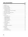
..............................................................................................................................................
1. Introduction ........................................................................................................................22
2. Intended Use .....................................................................................................................23
3. Scope of Delivery ..............................................................................................................24
4. Explanation of Symbols .....................................................................................................24
5. Safety Information .............................................................................................................24
a) GeneralNotes ...............................................................................................................24
b) Notes on Batteries/Rechargeable Batteries .................................................................26
6. Control Elements ...............................................................................................................27
7. Inserting/Replacing the Battery .........................................................................................28
8. Explanation of Symbols .....................................................................................................29
9. Operation ...........................................................................................................................30
10. Measuring ..........................................................................................................................30
a) Zero reconciliation ........................................................................................................30
b) Internal Battery Test .....................................................................................................30
c) Voltage Measurement ..................................................................................................31
d) Current Measurement ..................................................................................................32
e) Resistance Measuring..................................................................................................35
f) Continuity Test ..............................................................................................................35
g) Battery Test ..................................................................................................................36
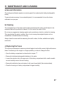
11. Maintenance and Cleaning ................................................................................................37
a) General Information .....................................................................................................37
b) Cleaning .......................................................................................................................37
c) Replacing the Fuses ....................................................................................................37
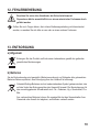
12. Troubleshooting .................................................................................................................38
13. Disposal .............................................................................................................................38
a) General Information .....................................................................................................38
b) Batteries/Rechargeable Batteries ................................................................................38
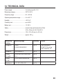
14. Technical Data ...................................................................................................................39

Dear customer,
Thank you for making the excellent decision of purchasing this Voltcraft
®
product.
Voltcraft® - This name stands for above-average quality products in the areas of measuring,
charging and grid technology, characterised by technical competence, extraordinary perfor-
mance and permanent innovation.
Whether you are an ambitious hobby electronics technician or a professional user - a product
of the Voltcraft
®
brand family will provide you with the best solution for even the most sophisti-
cated of tasks. Special features: We offer the sophisticated technology and reliable quality of
our Voltcraft
®
products at a near-unbeatable price/performance ratio. We lay the groundwork
for long, good and successful cooperation.
Enjoy your new Voltcraft
®
product!
All company names and product names are trademarks of their respective owners.
All rights reserved.
International: www.conrad.com/contact
United Kingdom: www.conrad-electronic.co.uk/contact

- Measuring and displaying electrical parameters in the range of the measuring category CAT
III up to max. 500 V against earth potential according to EN61010 and all lower categories.
- Direct and alternating voltage measurement up to max. 500 V
- Measuring direct currents of up to 10 A
- Measuring alternating currents of up to 500 mA
- Measuring resistances up to 10 MΩ
- Acoustic continuity test
- Battery Test
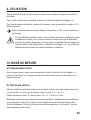
Only use with the stated type of battery.
The meter must not be operated when it is open, i.e. with an open battery compartment or
when the battery compartment cover is missing. Measurements in moist rooms or under detri-
ment ambience conditions such as wetness or high humidity, dust, ammable gases, vapours,
solvents, thunderstorm or strong electrostatic elds are not permissible.
For safety reasons, only use measuring lines or accessories which are adjusted to the speci-
cations of the meter when measuring.
Any use other than that described above damages the product. Moreover, this is linked to
dangers such as short circuit, re, electric shock, etc. No part of the product must be modied
or converted!
Read the operating instructions carefully and keep them for later reference.
Always observe the safety information!

• Analogue Multimeter
• Safety measuring lines (red and black)
• 2 x AA battery
• Operating Instructions
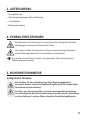
The triangle containing a lightning symbol warns against danger of electric shock or
impairment of the electrical safety of the device.
An exclamation mark in a triangle indicates important notes in these operating
instructions that must be strictly observed.
The “arrow” symbol indicates special information and advice on operating the device.

Dear Customer,
this safety information serves not only to protect the product, but also your own
safety and the safety of other persons. Therefore, read this chapter very carefully
before taking the product into operation!
This product left the manufacturer‘s factory in a safe and perfect condition. To
maintain this condition and to ensure safe operation, the user must observe the
safety information and warning notes in these operating instructions.
• Unauthorized conversion and/or modication of the product are not permissible
for safety and approval reasons (CE).
• The product is only suitable for operation in dry environments. The entire product
must not become damp or wet. Never touch it with wet hands to avoid damage to
it.
• This product is not a toy and not suitable for children!
• Do not leave packaging material unattended. It may become a dangerous toy for
children.
• The voltage between the connection points must not exceed the indicated
voltage.
• Be especially careful when dealing with voltages >25 V/AC or >35 V/DC! Even
at these voltages it is possible to receive a potentially fatal electric shock if you
touch electrical conductors.
• Never touch the measuring prods during measurement!
• Set the meter to the desired unit before any measurement. Incorrect measure-
ments may destroy the product!
• Always observe proper polarity when connecting the measuring lines to the
meter. (Red = Plus pole, Black = Minus pole).
• Check before each measurement that the meter or measuring lines are not
damaged. Never perform any measurements if the insulation or the product are
damaged otherwise!
• During each measurement, observe that the connections/measuring points do
not touch. Danger of short-circuit!

• Never operate the product in direct proximity of:
- Strong magnetic or electromagnetic elds
- transmitter aerials or HF generators.
• Observe the description of the gures in each chapter for each measurement. An
incorrect measurement could destroy the product and seriously injure the user.
• Remove the dust protection caps at the connection sockets before connecting
the measuring lines. Always install them after each measurement to avoid
contamination of the contacts.
• Keep batteries/rechargeable batteries out of the reach of children.
• Do not leave any batteries lying around openly. There is a risk of batteries being
swallowed by children or pets. If swallowed, consult a doctor immediately.
• Leaking or damaged batteries/rechargeable batteries may cause alkali burns
if they come in contact with the skin. It is therefore advisable to use suitable
protective gloves.
• Batteries/rechargeable batteries must not be short-circuited, disassembled or
thrown into re. There is a danger of explosion.
• Do not recharge normal, non-rechargeable batteries; danger of explosion!
• Always observe the polarity (positive/+ and negative/-) when inserting the battery.

?
PROTECTION
FUSE&DIODE
D
O
O
G
E
C
A
L
P
E
R
BAT
Ω
䌲
5K
2K
1K
10K
OHMS
OHMS
500
200
100
50
20
10
0
Ω
DC
DC
50
250
200
30
150
20
100
10
50
0
2
1.6
1.2
0.8
0.4
0
1
2
3
4
9
10
5
6
7
8
11
12
13
14
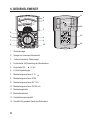
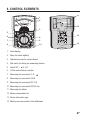
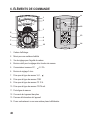
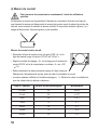
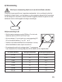
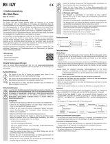
1. Scale display
2. Mirror for better legibility
3. Adjustment screw for scale indicator
4. Dial switch for setting the measuring function
5. Switch DC,
, Ω / AC
6. 0-Ohm reconciliation controller
7. Measuring line connection V, Ω,
8. Measuring line connection COM
9. Measuring line connection DC 10 A
10. Measuring line connection DC/AC mA
11. Measuring line holder
12. Battery compartment lid
13. Device information sign
14. Base for an even position of the Multimeter

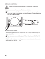
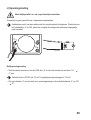
1. Switch off the meter before starting battery replacement.
2. Open the rear screw of the battery compartment with a small Phillips-head screwdriver.
3. Carefully remove lid of the battery compartment “12”.
4. If required, remove at batteries from the housing and insert two new batteries of the
same type (see technical data) into the battery compartment with the correct polarity.
5. Carefully replace the battery compartment lid on the meter and fasten it again with the
screw.

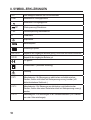
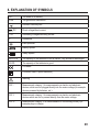
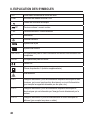
OFF The meter is in standby
COM The ground line connection
Acoustic continuity test
DC
Direct voltage/direct current
~ AC
Alternating voltage/alternating current
Ω Resistance
Earth potential
Battery symbol
Safety symbol
REPLACE The capacity of the batteries in use is limited. They should be exchanged
GOOD The capacity of the batteries is good
CE-tested
Protection class II (extra insulation)
Warning
CAT I Measurement category I for measurements on electric and electronic
devices, which are not plugged directly into the mains voltage (for example
devices powered by batteries, etc.).
CAT II Measurement category I for measurements on electric and electronic
devices which are run by current directly from the mains voltage.
CAT III Measurement category III for measurements in the building circuitry (for
example plugs or relays).

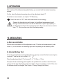
After insertion of the battery/rechargeable battery, you can start with the desired measuring
process.
For this, select the desired measuring value via the adjustment wheel “4”.
For details on measurement, see chapter “10“ Measuring.
Switch the meter to “OFF” after each measurement to save energy.
Observe the description in each chapter for the different measurement types!
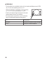
During a measurement make sure that the Multimeter is placed appropriately, or
an adequate base. Place the measurement device at on an even base or use the
base “14”. Other positions can distort the display reading.
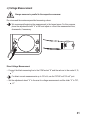
Perform zero reconciliation with the adjustment screw “3” before each measurement. (scale
value 0 V). At this moment, no measuring signal must be pending at the measuring lines!
To test the inserted battery/rechargeable battery for capacity, connect the black measuring line
to socket “8” and the red one to socket V, Ω,
“7”.
Place the adjustment wheel “4” to the area “Ω x 1” 10 Ohm or 1 Ohm.
Now place the two measuring points together and, parallel to this, conduct a zero-Ohm com-
parison until the right side display needle is at 0 Ohm. If it is not possible to reach 0 Ohm, then
the batteries should be changed. See Chapter 7 Placing/Changing the Battery.

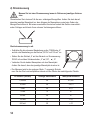
Do not exceed the maximum permitted measuring values.
We recommend beginning the measurement in the largest areas. For this purpose,
place the adjustment wheel “4” at 500 and adjust or correct the measurement size,
downwards, if necessary.
DC
AC
DC
AC
V
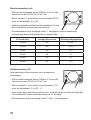
• Connect the black measuring line to the COM socket “8” and the red one to the socket V, Ω,
“7”.
For direct current measurements up to 100 mV, use the “DC/AC mA 100 mV” port.
• Set the adjustment wheel “4” to the area for voltage measurement and the slider “5” to “DC,
, Ω”.

• Connect the two measuring prods with the object to be measured
The measuring value is shown on the analogue scale “1”. Take the value and multiply it with
the values of the following table:
2 V 2 x 1
10 V 10 x 1
50 V 50 x 1
100 V 10 x 10
250 V 250 x 1
500 V 50 x 10
100 mV 10 x 10
• Connect the black measuring line to the COM socket “8” and the red one to the socket V, Ω,
“7”.
• Set the adjustment wheel “4” to the area for voltage measurement and the slider “5” to “AC“
• Connect the two measuring prods with the object to be measured.
• The measuring value is shown on the analogue scale “1”. Take the value and multiply it with
the values of the following table:
10 V 10 x 1
50 V 50 x 1
250 V 250 x 1
500 V 50 x 10

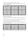
Do not exceed the maximum permitted measuring values. Always make sure that the given
measurement object is disconnected from the electrical current before the measurement points
are placed, or when the size of the measurement is changed. If the points should slip there is
the danger of a very serious electrical shock.
DC
AC
DC
AC
V
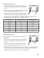
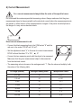
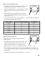
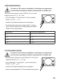
• Connect the black measuring line to the COM socket “8” and the
red one to the socket “DC/AC mA 100 mV”.
• Set the adjustment wheel “4” to the area for current measurement
DC/AC mA and the slider “5” to “DC,
, Ω“
• Connect the two measuring prods with the object to be measured.
Make sure that the given measurement object is disconnected
from the electrical current.
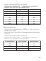
• The measuring value is shown on the analogue scale “1”. Take the value and multiply it with
the values of the following table:
0,05 mA 50 x 0,001
0,5 mA 50 x 0,01
5 mA 50 x 0,1
10 mA 10 x 1
50 mA 50 x 1
100 mA 10 x 10
500 mA 50 x 10

DC
AC
DC
AC
V
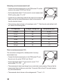
• Connect the black measuring line to the COM socket “8” and the
red one to the socket “DC/AC mA 100 mV”.
• Set the adjustment wheel “4” to the area for current measurement
DC/AC and the slider “5” to “AC“
• Connect the two measuring prods with the object to be measured.
Make sure that the given measurement object is disconnected
from the electrical current.
• The measuring value is shown on the analogue scale “1”. Take the value and multiply it with
the values of the following table:
0,25 mA 250 x 0,001
2,5 mA 250 x 0,01
25 mA 250 x 0,1
50 mA 50 x 1
250 mA 250 x 1
500 mA 50 x 10
DC
AC
DC
AC
V
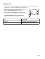
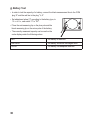
This connection is designed for a limited period of currency
measurement only.
• Connect the black measuring line to the COM socket “8” and
the red one to the socket “DC/AC mA 100 mV”.
• Set the adjustment wheel “4” to the area for current “10 A”
and the slider “5” to “DC,
, Ω“
• The measurement object must always have no electrical current passing. Observe that the
measurement does not take any more than 15 seconds. Wait at least 30 seconds between
any two measurements!
• The measured value is shown on the analogue scale “1” from 0 – 10

Connect the black measuring line to the COM socket “8” and
DC
AC
DC
AC
V
the red one to the socket V, Ω, “7”.
• Set the adjustment wheel “4” to the area Ω and the slider “5”
to “DC,
, Ω“
• Connect the two measuring prods with the object to be mea-
sured.
• The measuring value is shown on the analogue scale “1”.
Take the value and multiply it with the values of the following
table:
X 1 X 1
X 10 X 10
X 100 X 100
X 1K X 1000
• Connect the black measuring line to the COM socket “8” and
DC
AC
DC
AC
V
the red one to the socket V, Ω, , “7”.
• Set the adjustment wheel “4” to the area
, and the slider
“5” to “DC,
, Ω“
• Connect the two measuring prods with the object to be
measured
• A resistance value up to 40 Ohm will cause a signal to sound

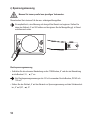
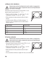
• In order to test the capacity of a battery, connect the black measurement line to the COM
plug “8“ and the red line to the plug “V, Ω.”
• Set adjustment wheel “4” according to the battery type, to
DC
AC
DC
AC
V
1.5 v. or 9 v., and switch “5” to “DC”.
• Place the red measuring tip on the plus pole and the
black measuring tip on the minus pole of the battery.
• The currently measured capacity can be read on the
scale display under the following values
BAT The battery is defective
REPLACE The battery should be exchanged soon
GODD The battery has adequate reserves

The analogue multimeter requires no servicing apart from replacing the battery/rechargeable
battery.
To warrant meter accuracy for an extended period, it is recommended to have the device
calibrated once per year.
The connected lines of the meter must be disconnected from the meter and all objects to be
measured before the produced is cleaned. For this, switch the meter off rst.
Do not use any aggressive cleaning agents such as petroleum, alcohol or similar for cleaning.
This may damage the meter‘s surface. Also do not use any sharp-edged objects such as
screwdrivers or medal brushes for cleaning.
Always clean the meter and the measuring lines with a clean, lint-free, antistatic and slightly
moist cloth.
The currency measurement areas are protected against overload by ceramic high-performance
fuses. If measuring in this range is no longer possible, you have to change the fuse.
• Open the battery compartment as describe din chapter “7”.
• Remove the batteries/rechargeable batteries in the meter
• Loosen the retention tab in the upper part of the battery compartment with a small screwdri-
ver and carefully remove the rear housing
• Remove the defective fuse and replace it with one of equal build. (See technical data)
• Close the housing incl. battery compartment lid again carefully

If you have any questions that are not answered in this manual, please contact our
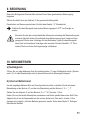
technical service or another specialist.
Dispose of the product according to the applicable statutory provisions at the end of
its service life.
You as the end user are required by law (Battery Ordinance) to return all used batteries/rechar-
geable batteries. Disposing of them in the household waste is prohibited.
Batteries containing hazardous substances are marked with the adjacent symbol to
indicate that disposal in the household waste is prohibited. The descriptions for the
respective heavy metals are: Cd = cadmium, Hg = mercury, Pb = lead.
You may return your used batteries free of charge to collection points in your
municipality and anywhere where batteries/rechargeable batteries are sold.

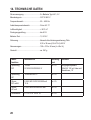
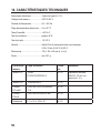
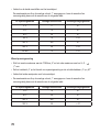
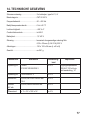
Power supply ........................................2 x battery type AA 1.5 V
Measuring category ..............................CAT III 500 V
Frequency range ..................................50 – 400 Hz
Operating temperature range ...............0 to +40 °C
Humidity ................................................< 80 % rF
Continuity test .......................................up to 40 Ω
Battery test ...........................................1.5 V/9 V
Safety ................................................... ceramic high-performance fuse Flink
6.35 x 32 mm (0.5 A/10 A) 500 V
Dimensions ...........................................150 x 102 x 54 mm (L x W x H)
Weight ..................................................approx. 261 g
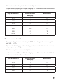
Voltage DC 100mV
2/10/50/100/250/500 V
± 4 % Input impedance
20 kΩ/V 100 mV via
mA connection “10“
Voltage AC 10/50/250/500 V ± 5 %
Current
DC mA/A
0,05/0,5/5/10/50/100/500 mA
10 A
± 4 %
Current
AC mA
0,25/2,5/25/50/250/500 mA ± 5 %
Resistance x 1/ x 10/ x 100/ x 1K ± 4 %
Page is loading ...
Page is loading ...
Page is loading ...
Page is loading ...
Page is loading ...
Page is loading ...
Page is loading ...
Page is loading ...
Page is loading ...
Page is loading ...
Page is loading ...
Page is loading ...
Page is loading ...
Page is loading ...
Page is loading ...
Page is loading ...
Page is loading ...
Page is loading ...
Page is loading ...
Page is loading ...
Page is loading ...
Page is loading ...
Page is loading ...
Page is loading ...
Page is loading ...
Page is loading ...
Page is loading ...
Page is loading ...
Page is loading ...
Page is loading ...
Page is loading ...
Page is loading ...
Page is loading ...
Page is loading ...
Page is loading ...
Page is loading ...
Page is loading ...
Page is loading ...
Page is loading ...
Page is loading ...

D
Dies ist eine Publikation der Conrad Electronic SE, Klaus-Conrad-Str. 1, D-92240 Hirschau (www.conrad.com).
Alle Rechte einschließlich Übersetzung vorbehalten. Reproduktionen jeder Art, z. B. Fotokopie, Mikroverlmung, oder die
Erfassung in elektronischen Datenverarbeitungsanlagen, bedürfen der schriftlichen Genehmigung des Herausgebers. Nach-
druck, auch auszugsweise, verboten. Die Publikation entspricht dem technischen Stand bei Drucklegung.
G
This is a publication by Conrad Electronic SE, Klaus-Conrad-Str. 1, D-92240 Hirschau (www.conrad.com).
All rights including translation reserved. Reproduction by any method, e.g. photocopy, microlming, or the capture in electronic
data processing systems require the prior written approval by the editor. Reprinting, also in part, is prohibited. This publication
represent the technical status at the time of printing.
F
Ceci est une publication de Conrad Electronic SE, Klaus-Conrad-Str. 1, D-92240 Hirschau (www.conrad.com).
Tous droits réservés, y compris de traduction. Toute reproduction, quelle qu‘elle soit (p. ex. photocopie, microlm, saisie dans
des installations de traitement de données) nécessite une autorisation écrite de l‘éditeur. Il est interdit de le réimprimer, même
par extraits. Cette publication correspond au niveau technique du moment de la mise sous presse.
O
Dit is een publicatie van Conrad Electronic SE, Klaus-Conrad-Str. 1, D-92240 Hirschau (www.conrad.com).
Alle rechten, vertaling inbegrepen, voorbehouden. Reproducties van welke aard dan ook, bijvoorbeeld fotokopie, microver-
lming of de registratie in elektronische gegevensverwerkingsapparatuur, vereisen de schriftelijke toestemming van de uitge-
ver. Nadruk, ook van uittreksels, verboden. De publicatie voldoet aan de technische stand bij het in druk bezorgen.
V3_0115_02/VTP
-
 1
1
-
 2
2
-
 3
3
-
 4
4
-
 5
5
-
 6
6
-
 7
7
-
 8
8
-
 9
9
-
 10
10
-
 11
11
-
 12
12
-
 13
13
-
 14
14
-
 15
15
-
 16
16
-
 17
17
-
 18
18
-
 19
19
-
 20
20
-
 21
21
-
 22
22
-
 23
23
-
 24
24
-
 25
25
-
 26
26
-
 27
27
-
 28
28
-
 29
29
-
 30
30
-
 31
31
-
 32
32
-
 33
33
-
 34
34
-
 35
35
-
 36
36
-
 37
37
-
 38
38
-
 39
39
-
 40
40
-
 41
41
-
 42
42
-
 43
43
-
 44
44
-
 45
45
-
 46
46
-
 47
47
-
 48
48
-
 49
49
-
 50
50
-
 51
51
-
 52
52
-
 53
53
-
 54
54
-
 55
55
-
 56
56
-
 57
57
-
 58
58
-
 59
59
-
 60
60
-
 61
61
-
 62
62
-
 63
63
-
 64
64
-
 65
65
-
 66
66
-
 67
67
-
 68
68
-
 69
69
-
 70
70
-
 71
71
-
 72
72
-
 73
73
-
 74
74
-
 75
75
-
 76
76
-
 77
77
-
 78
78
-
 79
79
-
 80
80


VOLTCRAFT 1009621 Operating Instructions Manual
- Category
- Cable network testers
- Type
- Operating Instructions Manual
- This manual is also suitable for
Ask a question and I''ll find the answer in the document
Finding information in a document is now easier with AI
in other languages
- français: VOLTCRAFT 1009621
- Deutsch: VOLTCRAFT 1009621
- Nederlands: VOLTCRAFT 1009621
Related papers
-
VOLTCRAFT VC-7055BT User manual
-
VOLTCRAFT VC135 Safety Instructions
-
-
-
-
-
-
VOLTCRAFT VC-125 Operating Instructions Manual
-
-
Other documents
-
 Reely 1877013 Operating instructions
-
Basetech FM-10 Owner's manual
-
Conrad Components 5-Channel LED Running Light Module Operating instructions
-
Laserliner MultiMeter-Home Owner's manual
-
-
 Reely 1877012 Operating instructions
-
-
-
Velleman VTSET24 User manual
-
Facom 711A Owner's manual

