Ingersoll-Rand AVC26 Operation and Maintenance Manual
- Category
- Power tools
- Type
- Operation and Maintenance Manual

Refer All Communications to the Nearest
Ingersoll–Rand Office or Distributor.
Ingersoll–Rand Company 1999
Printed in U.S.A.
03528742
Form P6408
Edition 12
June, 1999
OPERATION AND MAINTENANCE MANUAL
FOR MODELS AVC10, AVC12, AVC13,
AND AVC26 LIGHTWEIGHT RIVETING HAMMERS
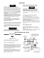
Models AVC10, AVC12, AVC13 and AVC26 Lightweight Riveting Hammers are designed for
riveting door and window frames, sheet metal, lightweight plate and riveting skin on all types of
air and spacecraft.
Ingersoll–Rand is not responsible for customer modification of tools for applications on which
Ingersoll–Rand was not consulted.
IMPORTANT SAFETY INFORMATION ENCLOSED.
READ THIS MANUAL BEFORE OPERATING TOOL.
IT IS THE RESPONSIBILITY OF THE EMPLOYER TO PLACE THE INFORMATION
IN THIS MANUAL INTO THE HANDS OF THE OPERATOR.
FAILURE TO OBSERVE THE FOLLOWING WARNINGS COULD RESULT IN INJURY.
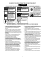
PLACING TOOL IN SERVICE
• Always operate, inspect and maintain this tool in
accordance with American National Standards
Institute Safety Code for Portable Air Tools
(ANSI B186.1).
• For safety, top performance, and maximum durability
of parts, operate this tool at 90 psig (6.2 bar/620 kPa)
maximum air pressure at the inlet with 1/2” (13 mm)
inside diameter air supply hose.
• Always turn off the air supply and disconnect the air
supply hose before installing, removing or adjusting
any accessory on this tool, or before performing any
maintenance on this tool.
• Do not use damaged, frayed or deteriorated air hoses
and fittings.
• Be sure all hoses and fittings are the correct size and
are tightly secured. See Dwg. TPD905–1 for a typical
piping arrangement.
• Always use clean, dry air at 90 psig maximum air
pressure. Dust, corrosive fumes and/or excessive
moisture can ruin the motor of an air tool.
• Do not lubricate tools with flammable or volatile
liquids such as kerosene, diesel or jet fuel.
• Do not remove any labels. Replace any damaged label.
USING THE TOOL
• Always wear eye protection when operating or
performing maintenance on this tool.
• Always wear hearing protection when operating this
tool.
• Keep hands, loose clothing and long hair away from
impacting end of tool.
• Anticipate and be alert for sudden changes in motion
during start up and operation of any power tool.
• Keep body stance balanced and firm. Do not
overreach when operating this tool. High reaction
torques can occur at or below the recommended air
pressure.
• Tool accessory may continue to impact briefly after
throttle is released.
• Air powered tools can vibrate in use. Vibration,
repetitive motions or uncomfortable positions may be
harmful to your hands and arms. Stop using any tool
if discomfort, tingling feeling or pain occurs. Seek
medical advice before resuming use.
• Use accessories recommended by Ingersoll–Rand.
• Never operate a Percussion Tool unless an accessory is
properly installed and the tool is held firmly against
the work.
• Always use a retainer, when furnished, in addition to
proper barriers to protect persons in surrounding or
lower areas from possible ejected accessories.
• This tool is not designed for working in explosive
atmospheres.
• This tool is not insulated against electric shock.
The use of other than genuine Ingersoll–Rand replacement parts may result in safety hazards, decreased tool performance, and
increased maintenance, and may invalidate all warranties.
Repairs should be made only by authorized trained personnel. Consult your nearest Ingersoll–Rand Authorized Servicenter.
F
E
P
TPD1378

2
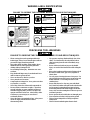
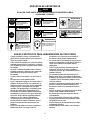
WARNING LABEL IDENTIFICATION
FAILURE TO OBSERVE THE FOLLOWING WARNINGS COULD RESULT IN INJURY.
Always wear eye protection
when operating or perform-
ing maintenance on this
tool.
WARNING
WARNING
Always wear hearing
protection when operating
this tool.
Always turn off the air sup-
ply and disconnect the air
supply hose before install-
ing, removing or adjusting
any accessory on this tool,
or before performing any
maintenance on this tool.
WARNING
Air powered tools can vibrate
in use. Vibration, repetitive
motions or uncomfortable po-
sitions may be harmful to your
hands and arms. Stop using
any tool if discomfort, tingling
feeling or pain occurs. Seek
medical advice before resum-
ing use.
WARNING
Do not carry the tool by
the hose.
WARNING
WARNING
Do not use damaged, frayed
or deteriorated air hoses
and fittings.
WARNING
Keep body stance balanced
and firm. Do not overreach
when operating this tool.
WARNING
Operate at 90 psig (6.2 bar/
620 kPa) Maximum air pressure.
90 psig
(6.2bar/620kPa)
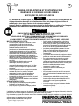
PERCUSSIVE TOOL WARNINGS
FAILURE TO OBSERVE THE FOLLOWING WARNINGS COULD RESULT IN INJURY.
• When wearing gloves and operating models with
inside trigger, always be sure that the gloves will not
prevent the trigger from being released.
• Wear safety shoes, hard hat, safety goggles, gloves,
dustmask and any other appropriate protective
clothing while operating the tool.
• Do not indulge in horseplay. Distraction can cause
accidents.
• Keep hands and fingers away from the throttle lever
until it is time to operate the tool.
• Never rest the tool or chisel on your foot.
• Never point the tool at anyone.
• Compressed air is dangerous. Never point an air hose
at yourself or co–workers.
• Never blow clothes free of dust with compressed air.
• Be sure all hose connections are tight. A loose hose
not only leaks but can come completely off the tool
and while whipping under pressure, can injure the
operator and others in the area. Attach safety cables
to all hoses to prevent injury in case a hose is
accidentally broken.
• Never disconnect a pressurized air hose. Always turn
off the air supply and bleed the tool before
disconnecting a hose.
• The operator must keep limbs and body clear of the
chisel. If a chisel breaks, the tool with the broken
chisel projecting from the tool will suddenly surge
forward.
• Do not ride the tool with one leg over the handle.
Injury can result if the chisel breaks while riding the
tool.
• Know what is underneath the material being worked.
Be alert for hidden water, gas, sewer, telephone or
electric lines.
• Use only proper cleaning solvents to clean parts. Use
only cleaning solvents which meet current safety and
health standards. Use cleaning solvents in a well
ventilated area.
• Do not flush the tool or clean any parts with diesel
fuel. Diesel fuel residue will ignite in the tool when the
tool is operated, causing damage to internal parts.
When using models with outside triggers or throttle
levers, take care when setting the tool down to prevent
accidental operation.
• Do not operate the tool with broken or damaged parts.
• Never start the tool when it is lying on the ground.
• This tool is not designed for working in explosive
atmospheres.
• This tool is not insulated against electric shock.

3
ADJUSTMENTS
Keep the Handle tight on the Barrel.
After the first 24 hours of operation, remove the Exhaust
Deflector and Locking Key. Clamp the Barrel flats in a
leather–covered or copper–covered vise and using a wrench
at least 12” (305 mm) long, draw the handle as tightly as
possible. For aluminum handles, tighten to 160 ft–lb
(216 Nm) torque. For all other Handles, tighten to 180
ft–lb (244 Nm) torque.
Do not attempt to pry apart the two sections of the
Valve Box. Grasp the front section in the hand and insert a
rod that will pass through the Valve and contact the rear
section. Lightly strike the rod until the two sections are
separated.
Keep the front and rear sections of a Valve Box as a
unit. They are factory matched and must not be
mismatched.
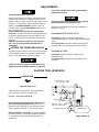
SETTING THE POWER REGULATOR
With the exception of the AVC10C1, all the Riveters have a
power regulator that allows the operator to adjust power
output. To adjust the power, proceed as follows:
Always turn off the air supply and disconnect the air
supply hose before installing, removing, or adjusting
any accessory on this tool, or before performing any
adjustments of the tool.
Never operate the tool unless an accessory is properly
installed and held firmly against the work.
Experience will indicate how much power regulation is
required for each job.
For Models AVC10, AVC12, AVC13
For full power, rotate the Throttle Adjusting Knob
counterclockwise until you get full trigger travel (maximum
power).
For reduced power, rotate the Throttle Adjusting Knob
clockwise until you get less trigger travel (less power).
For Model AVC26B1
For full power, rotate the Power Adjusting Valve
counterclockwise.
For reduced power, rotate the Power Adjusting Valve
clockwise.
PLACING TOOL IN SERVICE
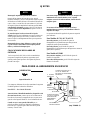
LUBRICATION
Ingersoll–Rand No. 10
Always use an air line lubricator. We recommend the
following Filter–Lubricator–Regulator Unit:
For USA – No. C18–03–FKG0–28
Before starting the Riveting Hammer and after each
two or three hours of operation, unless the air line
lubricator is used, detach the air hose and inject several
drops of Ingersoll–Rand No. 10 Oil into the air inlet.
When the Hammer is to be idle for a period exceeding
24 hours, lubricate it in the regular manner and operate it
for 5 seconds to coat the internal parts with the oil to
prevent rust.
MAIN LINES 3 TIMES
AIR TOOL INLET SIZE
TO
AIR
SYSTEM
TO
AIR
TOOL
LUBRICATOR
REGULATOR
FILTER
BRANCH LINE 2 TIMES
AIR TOOL INLET SIZE
DRAIN REGULARLY
COMPRESSOR
(Dwg. TPD905–1)

4
SPECIFICATIONS
Model Handle Power
Regulator
Blows per min. Piston Stroke
in (mm)
AVC10C1
button throttle – – – – 3,200 1–7/8 (47)
AVC10A1
offset built–in 3,200 1–7/8 (47)
AVC12A1
offset built–in 2,100 3 (76)
AVC13A1
offset built–in 1,725 4 (101)
AVC26A1
offset built–in 1,120 6 (152)
AVC26B1
pistol grip built–in 1,120 6 (152)
Page is loading ...
Page is loading ...
Page is loading ...
Page is loading ...
Page is loading ...
Page is loading ...
Page is loading ...
Page is loading ...
Page is loading ...
Page is loading ...
Page is loading ...
Page is loading ...

17
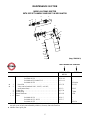
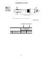
MAINTENANCE SECTION
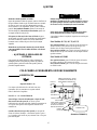
MODEL AVC26A1 RIVETER
WITH OFFSET HANDLE AND BUILT–IN REGULATOR
(Dwg. TPB558–3)
10A
10
9
8
11
6
2
14
26
15
16
17
25
22
21
20
18
24
23
19
12
1
PART NUMBER FOR ORDERING
AVC10, AVC12 AVC26
AVC13
Valve Box Assembly
for Model AVC10 . . . . . . . . . . . . . . . . . . . . . . . . . . . . . AV10–A4 –––
for Models AVC12 and AVC13 . . . . . . . . . . . . . . . . . . . AV11–A4 –––
for Model AVC26 . . . . . . . . . . . . . . . . . . . . . . . . . . . . . ––– AV24–A4A
♦ 1 Dowel Pin . . . . . . . . . . . . . . . . . . . . . . . . . . . . . . . . . . . . . . . . . . . AV11–32 AV 11 –32
♦ 2 Valve (can be furnished 0.001”, 0.0015”, or 0.002”;
see Oversize Parts) . . . . . . . . . . . . . . . . . . . . . . . . . . . . . . . . . . . . . AV11–2 AV24–2
3 Locking Key . . . . . . . . . . . . . . . . . . . . . . . . . . . . . . . . . . . . . . . . . . . . AV 11 –34 –––
4 Locking Ring . . . . . . . . . . . . . . . . . . . . . . . . . . . . . . . . . . . . . . . . . . . . ––– K–196A
• 5 Exhaust Deflector . . . . . . . . . . . . . . . . . . . . . . . . . . . . . . . . . . . . . . . . AV 11 –85 K–85A
• 6 Piston
for Model AVC10 . . . . . . . . . . . . . . . . . . . . . . . . . . . . . AV10–5 –––
for Model AVC12, AVC13 . . . . . . . . . . . . . . . . . . . . . . AV12–5 –––
for Model AVC26 . . . . . . . . . . . . . . . . . . . . . . . . . . . . . ––– AV24–5A
• To keep downtime to a minimum, it is desirable to have on hand certain repair parts. We recommend that you stock
one (pair or set) of each part indicated by a bullet (•) for every four tools in service.
♦ Indicates Tune–up Kit part.

18
MAINTENANCE SECTION
PART NUMBER FOR ORDERING
AVC10, AVC12 AVC26
AVC13
7 Barrel
for Model AVC10 only . . . . . . . . . . . . . . . . . . . . . . . . . . . AVC10–6 –––
for Model AVC10–EU only . . . . . . . . . . . . . . . . . . . . . . . . AVC10–EU–6 –––
for Model AVC12 only . . . . . . . . . . . . . . . . . . . . . . . . . . . AVC12–6 –––
for Model AVC12–EU only . . . . . . . . . . . . . . . . . . . . . . . . AVC12–EU–6 –––
for Model AVC13 . . . . . . . . . . . . . . . . . . . . . . . . . . . . . . . AVC13–6 –––
for Model AVC13–EU . . . . . . . . . . . . . . . . . . . . . . . . . . . . AVC13–EU–6 –––
* Warning Label
for AVC10, AVC12 and AVC13 . . . . . . . . . . . . . . . . . . . . WARNING–6–99 –––
for AVC10–EU, AVC12–EU and AVC13–EU . . . . . . . . . EU–99 –––
8 Barrel Assembly with 0.498” bore Nozzle
for AVC26 . . . . . . . . . . . . . . . . . . . . . . . . . . . . . . . . . . . . . ––– AVC26–A6A
for AVC26–EU . . . . . . . . . . . . . . . . . . . . . . . . . . . . . . . . . . ––– AVC26–EU–A6A
* Warning Label
for AVC26 . . . . . . . . . . . . . . . . . . . . . . . . . . . . . . . . . . . . . ––– WARNING–6–99
for AVC26–EU . . . . . . . . . . . . . . . . . . . . . . . . . . . . . . . . . . ––– EU–99
9 Nozzle (0.498” bore) . . . . . . . . . . . . . . . . . . . . . . . . . . . . . . . . . . . ––– AV24–219
Nozzle (0.401” bore) . . . . . . . . . . . . . . . . . . . . . . . . . . . . . . . . . . . ––– AV24–19
♦• 10 Safety Set Retainer
for 0.401” diameter Shanks (Beehive) . . . . . . . . . . . . . . . AVC1–83 AVC1–83
for 0.498” diameter Shanks . . . . . . . . . . . . . . . . . . . . . . . . ––– AVC24–283
10A Accessory (Ingersoll–Rand offers a complete line of Jacksets
and Chisels. Inquire at nearest Office for types and prices.)
11 Offset Handle . . . . . . . . . . . . . . . . . . . . . . . . . . . . . . . . . . . . . . . . . . . . AV 11 –A59F AV24–A59B
Offset Handle (Bare Handle) . . . . . . . . . . . . . . . . . . . . . . . . . . . . . ––– AV24–59B
• 12 Trigger . . . . . . . . . . . . . . . . . . . . . . . . . . . . . . . . . . . . . . . . . . . . . . AV1–93A AV 1 –93A
• 13 Intermediate Lever . . . . . . . . . . . . . . . . . . . . . . . . . . . . . . . . . . . . . AV1–56 AV1 –56
♦ 14 Intermediate Lever Pin . . . . . . . . . . . . . . . . . . . . . . . . . . . . . . . . . LG2–191 LG2–191
15 Throttle Valve Assembly . . . . . . . . . . . . . . . . . . . . . . . . . . . . . . . . AVC10–A302 AVC10–A302
♦• 16 Throttle Valve Seal . . . . . . . . . . . . . . . . . . . . . . . . . . . . . . . . . 401–159 401–159
♦ 17 Throttle Valve Spring . . . . . . . . . . . . . . . . . . . . . . . . . . . . . . . . . . . H80–11 H80–11
Throttle Adjuster Assembly . . . . . . . . . . . . . . . . . . . . . . . . . . . . . . AV1–A250 AV 1 –A250
18 Throttle Adjuster Body . . . . . . . . . . . . . . . . . . . . . . . . . . . . . . AV1–250 AV 1 –250
19 Throttle Adjuster Screw . . . . . . . . . . . . . . . . . . . . . . . . . . . . . . AV1–252 AV 1 –252
♦ 20 Throttle Adjuster Stop Spring . . . . . . . . . . . . . . . . . . . . . . . . . AV1–256 AV 1 –256
♦ 21 Throttle Adjuster Stop Ball (1/8” diameter Steel) . . . . . . . . . AV1–255 AV 1 –255
22 Throttle Adjuster Knob . . . . . . . . . . . . . . . . . . . . . . . . . . . . . . AV1–251 AV 1 –251
23 Throttle Adjuster Sleeve . . . . . . . . . . . . . . . . . . . . . . . . . . . . . AV1–253 AV 1 –253
♦ 24 Throttle AdjusterSleeve Seal . . . . . . . . . . . . . . . . . . . . . . R0BR1C–283 R0BR1C–283
25 Throttle Adjuster Cap Screw . . . . . . . . . . . . . . . . . . . . . . . . . . AV1–254 AV 1 –254
26 Air Inlet Bushing . . . . . . . . . . . . . . . . . . . . . . . . . . . . . . . . . . . . . . N00–82 N00–82
* Quick–Change Rivet Set Retainer (for Jacksets with
0.401” diameter Shank) . . . . . . . . . . . . . . . . . . . . . . . . . . . . . . . . . . . . AVC10–183A AVC10–183A
* Hose Whip (8’ x 5/16” hose) . . . . . . . . . . . . . . . . . . . . . . . . . . . . . . . . R0–130 R0–130
* Male Hose Nipple (5/16” hose to 1/4” male pipe) . . . . . . . . . . . . . . . AV 1 –46 AV 1 –46
* Female Hose Nipple (5/16” hose to 3/8” female pipe) . . . . . . . . . . . . R1–47 R1–47
* Not illustrated.
• To keep downtime to a minimum, it is desirable to have on hand certain repair parts. We recommend that you stock
one (pair or set) of each part indicated by a bullet (•) for every four tools in service.
♦ Indicates Tune–up Kit part.

19
MAINTENANCE SECTION
PART NUMBER FOR ORDERING
AVC10, AVC12 AVC26
AVC13
* Tune–Up Kit (includes illustrated items 1, 2, 10, 14, 16, 17, 20,
21, 24, 105A and 108 . . . . . . . . . . . . . . . . . . . . . . . . . . . . . . . . . . . . . . . AVC10–TK2 –––
* Tune–Up Kit (includes illustrated items 1, 2, 10, 14, 16, 17, 20,
21 and 24) . . . . . . . . . . . . . . . . . . . . . . . . . . . . . . . . . . . . . . . . . . . . . . . ––– AVC26–TK1
* Not illustrated.
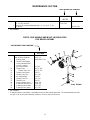
PISTOL GRIP HANDLE AND BUILT–IN REGULATOR
FOR MODEL AVC26B1
PART NUMBER FOR ORDERING
AVC26B1
27 Pistol Grip Handle with
Built–in Power Regulator . . . . AV24–1A
* Warning Label . . . . . . . . . . WARNING–6–99
28 Throttle Valve Plunger
(can be furnished 0.005”
or 0.010” oversize,
see Oversize Parts) . . . . . . . AV1–64
• 29 Throttle Valve . . . . . . . . . . AVC11–402
30 Throttle Valve Face . . . . AVC11–259
31 Throttle Valve Spring . . . . . H02–51
32 Throttle Valve Cap . . . . . . . AV1–109
33 Air Inlet Bushing . . . . . . . . N00–82
34 Throttle Lever Pin . . . . . . . R1A–191
35 Throttle Lever . . . . . . . . . . N00–78
36 Power Adjusting Valve . . . AV24–161
37 Adjusting Valve Stop Pin . . 502B–120
38 Adjusting Valve Washer . . AV1–164
39 Adjusting Valve Spring . . . AV 1 –165
* Not illustrated.
• To keep downtime to a minimum, it is desirable to have on hand certain repair parts. We recommend that you stock
one (pair or set) of each part indicated by a bullet (•) for every four tools in service.
(Dwg. TPA180)

20
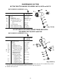
MAINTENANCE SECTION
BUTTON THROTTLE HANDLE FOR MODELS AVC10, AVC12 and AVC13
PART NUMBER FOR ORDERING
AVC10C1
40 Button Throttle Handle
Assembly . . . . . . . . . . . . . . . . . . . . AV 11 –A160
41 Head Block . . . . . . . . . . . . . . . AV11–160
42 Throttle Valve Button . . . . . . . R00AR2C–305A
43 Push Button Throttle Valve . . . AVC10C1–49
44 Button Throttle Valve
Face . . . . . . . . . . . . . . . . . . R2F–167
45 Air Inlet Bushing . . . . . . . . . . . N00–82
46 Button Throttle Valve Cap . . . . WF–109A
47 Button Throttle Valve Spring . . 4U–664–10
OFFSET HANDLE WITH INDEPENDENT POWER REGULATOR
FOR MODELS AVC10, AVC12 and ACV13
PART NUMBER FOR ORDERING
AVC10, AVC12,
AVC13
100 Offset Handle with
Independent Power
Regulator . . . . . . . . . . . . . . . . AV 11 –B59F
• 101 Trigger . . . . . . . . . . . . . . . AV1–93A
102 Intermediate Lever . . . . . . AV1–56
103 Intermediate Lever Pin . . LG2–191
104 Throttle Valve Assembly . AVC10–A302
♦• 105A Throttle Valve Seal . . 401–159
♦ 108 Throttle Valve Spring . . . . H80–11
109 Throttle Valve Cap . . . . . . AV11–109
Independent Power
Regulator Assembly . . . . AV11–A915
110 Independent Power
Regulator Body . . . . . AV11–915
111 Independent Power
111 Regulator Cap . . . . . . AV11–916
112 Independent Power
Regulator Spring (2) . AV 11 –917
• To keep downtime to a minimum, it is desirable to have on hand certain repair parts. We recommend that you stock
one (pair or set) of each part indicated by a bullet (•) for every four tools in service.
♦ Indicates Tune–up Kit part.
(Dwg. TPC139)
(Dwg. TPB129–1)

21
MAINTENANCE SECTION
PART NUMBER FOR ORDERING
AVC10, AVC12, AVC26
AVC13
Valve
0.001” oversize . . . . . . . . . . . . . . . . . . . . . . . . . . . . . . . . . . . . . . . . . . . . . . . . . . –––– AV24–2–10
MAINTENANCE TOOLS
TOOL NUMBER FOR ORDERING NAME OF TOOL OPERATION
34SR–54 Exhaust Deflector Pliers Removing or applying the Exhaust
Deflector (5).

22
MAINTENANCE SECTION
CENTERING SLEEVE TYPE NAIL SET ASSEMBLY
WITH RUBBER RETAINER
7/16 & 1/2 FOR SIZES AVC10, AVC12, AVC13, AVC26 AND AVC27
(Dwg. TPC591–1)
PART NUMBER FOR ORDERING
0.401” Diameter Shank
Nail Set Model
7/16” 1/2”
160 Nail Set Assembly . . . . . – – – – AVC12–A530–16
161 Centering Sleeve . . . . AVC12–531–14 – – – –

23
MAINTENANCE SECTION
Always wear eye protection when operating or
performing maintenance on this tool.
Always turn off air supply and disconnect air supply
hose before installing, removing or adjusting any
accessory on this tool, or before performing any
maintenance on this tool.
LUBRICATION
Each time the Models AVC10, AVC12, AVC13, or AVC26
Riveters are disassembled for maintenance, repair or
replacement of parts, lubricate the tool as follows:
Inject a few drops of Ingersoll–Rand No. 50 Oil into
the air inlet before attaching the air hose.
DISASSEMBLY
General Instructions
1. Do not disassemble the tool any further than
necessary to replace or repair damaged parts.
2. When grasping a tool or part in a vise, always use
leather–covered or copper–covered vise jaws to
protect the surface of the part and help prevent
distortion. This is particularly true of threaded
members and housings.
3. Do not remove any part which is a press fit in or on a
subassembly unless the removal of that part is
necessary for repairs or replacement.
4. Do not disassemble the tool unless you have a
complete set of new gaskets and O–rings for
replacement.
Disassembly of the Riveting Hammer
1. Clamp the Handle (11, 27, 41) of the Riveting
Hammer in leather–covered or copper–covered vise
jaws with the accessory end upward.
2. Remove the Set Retainer (10) and any Accessory
(10A) from the Barrel (7, 8).
3. Remove the Exhaust Deflector (5) from the Barrel.
4. Remove the Locking Key (3) or Locking Ring (4) that
keeps the Barrel from unscrewing from the Handle
Assembly (11, 27, 41).
5. Carefully unscrew the Barrel from the Handle
Assembly.
6. Remove the Piston (6) and the Valve Box Assembly.
Disassembly of the Throttle Mechanism
Clamp the handle of the Riveting Hammer in
leather–covered or copper–covered vise jaws with the
Air Inlet Bushing (26, 33, 45) upward.
For Offset Handle Models
1. Remove the Throttle Body Adjuster (18).
2. Unscrew the Throttle Adjuster Cap Screw (25) and
remove the Throttle Adjuster Knob (22), Throttle
Adjuster Stop Ball (21), Throttle Adjuster Stop Spring
(20), and the Throttle Adjuster Sleeve (23).
3. Remove the Throttle Adjuster Screw (19), the
Throttle Valve Spring (17), and the Throttle Valve
Assembly (15) from the Handle.
4. Remove the Air Inlet Bushing.
5. Rotate the Handle in the vise to gain access to the
Intermediate Lever Pin (14). Drive out the Pin.
6. Carefully remove the Trigger (12) and the
Intermediate ever (13).
For Pistol Handle Models
1. Unscrew the Throttle Valve Cap (32) and remove the
Throttle Valve Spring (31), and the Throttle Valve
(29).
2. Rotate the Handle in the vise, inlet downward.
3. Drive out the Throttle Lever Pin (34) and remove the
Throttle Lever (35).
4. Push the Throttle Valve Plunger (28) out through the
Handle.
5. Drive the Adjusting Valve Stop Pin (37) out of the
Power Adjusting Valve (36).
6. Remove the Power Adjusting Valve, Adjusting Valve
Washer (38), and the Adjusting Valve Spring (39).
For the Button Throttle Model
1. Unscrew the Button Throttle Valve Cap (46).
2. Unscrew the Throttle Valve Button (42).
3. Remove the Button Throttle Valve Spring (47) and the
Push Button Throttle Valve (43).
Disassembly of the Valve Box Assembly
1. Separate the two halves of the Valve Box Assembly.
A small brass or plastic hammer may be needed to
gently tap the Valve Box apart.
2. Carefully remove the Dowel Pin (1) and the Valve (2).
ASSEMBLY
General Instructions
1. Whenever grasping a tool or part in a vise, always use
leather–covered or copper–covered vise jaws. Take
extra care with threaded parts and housings.
2. Always clean every part and wipe every part with a
thin film of oil before installation.
3. Apply a film of O–ring lubricant to all O–rings before
final assembly.

24
MAINTENANCE SECTION
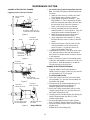
Assembly of the Valve Box Assembly
Lapping Oversize Valve into Valve Box
Figure 1
Figure 2
Figure 3
Figure 4
(Dwg. TPB130)
VALVE LAPPING
ARBOR
VALVE
TIGHTEN SCREW SLIGHTLY
TO RETAIN VALVE ON ARBOR
VALVE
VALVE BOX
REAR SECTION
KEEP FREE
OF LAPPING
COMPOUND
B C C
VALVE BOX
FRONT SECTION
KEEP FREE OF
LAPPING COMPOUND
VALVE
VALVE BOX
FRONT SECTION
VALVE BOX
REAR SECTION
PRESS DOWEL PIN IN
TO THIS DIMENSION
CLEAN HOLES WITH
1/32” DRILL
1/8”
1. An oversize Valve (2) must be lapped into the Valve
Box. Use Grade 320 lapping compound and proceed
as follows:
a. Install the Valve on the No. 29189 or No. 29407
Valve Lapping Arbor as shown in Figure 1.
b. Apply lapping compound to diameter “C” only;
keep diameter “B” free of compound at all times.
Insert the compound–coated end of the Valve into
the rear section of the Valve Box as shown in
Figure 2 and lap until a free fit is obtained.
c. Wipe all compound from the Valve and from
internal diameter “B” in the Valve Box. Allow the
compound to remain on internal diameter “C”.
d. Install the front section of the Valve Box and
Valve on the Arbor as shown in Figure 3.
e. Apply compound to Valve diameter “A” and lap
the small end of the valve to a free fit in the front
section.
f. Slide the rear section of the Valve Box over the
Valve and assemble it on the front section as
shown in Figure 4. Lap the Valve until it fits
freely in the assembled Valve Box.
2. Disassemble the Valve Box, clean the air ports with a
1/32” drill and wash the Valve and both sections of
the Valve Box in suitable solution to remove all trace
of the compound.
3. Apply 6 or 8 drops of light oil to the external surface
of the Valve and assemble it with the Dowel Pin (1) in
the Valve Box. Shake the assembly to see that the
Valve moves freely in the Valve Box.
Assembly of the Throttle Mechanism
Clamp the handle of the Riveting Hammer in
leather–covered or copper–covered vise jaws with the
Air Inlet Bushing (26, 33, 45) upward.
For Offset Handle Models
1. With a new Throttle Valve Seal (16) on the Throttle
Valve Assembly (15), place the Valve Assembly into
the Handle, Seal upward.
2. With the stem of the Throttle Adjusting Screw (19)
going through the Throttle Valve Spring (17),
install the Spring/Screw into the Handle.
3. With a new Throttle Adjust Sleeve Seal (24) on the
Throttle Adjuster Sleeve (23), place the Sleeve into
the Throttle Adjuster Body (18).
4. Carefully place the Throttle Adjuster Stop Spring (20)
and the Throttle Adjuster Stop Ball (21) in the
Throttle Adjuster Body.
5. Secure the Spring/Ball with the Throttle Adjuster
Knob (22) and the Throttle Adjuster Cap Screw (25).
6. Secure the Throttle Adjuster Screw with the Throttle
Adjuster Body.
7. Reinstall the Air Inlet Bushing (26).

25
MAINTENANCE SECTION
For Pistol Grip Handle Models
1. With a new Throttle Valve Face (30) installed on the
Throttle Valve (29), insert the Valve into the
Handle (27), slotted end down.
2. Place the Throttle Valve Spring (31) into the Handle
and secure with the Throttle Valve Cap (32).
3. Reinstall the Air Inlet Bushing (33).
4. Rotate the Handle in the vise to allow reinstallation of
the Throttle Lever (35).
5. Place the Throttle Valve Plunger (28) into the plunger
bore in the Handle.
6. Place the Throttle Lever into the Handle and secure
with the Throttle Lever Pin (34).
7. Put the Power Adjusting Valve (36) through the
Adjusting Valve Washer (38), raised detents of the
Washer toward the head of the Adjusting Valve, and
the Adjusting Valve Spring (39).
8. Screw the Adjusting Valve into the Handle.
9. Carefully drive the Adjusting Valve Stop Pin (37) into
the Power Adjusting Valve.
For the Button Throttle Model
1. Place the Push Button Throttle Valve (43) into the
Head Block (41).
2. Install the Button Throttle Valve Spring (47) and
secure it with the Button throttle Valve Cap (46).
3. Reinstall the Throttle Valve Button (42).
Assembly of the Riveting Hammer
1. Clamp the Handle of the Riveting Hammer in
leather–covered or copper–covered vise jaws with the
barrel bore upward.
2. Place the Valve Box Assembly into the Handle, larger
half of the Valve Box in first.
3. With the Piston (6) in the bore of the Barrel (7, 8),
screw the Barrel into the Handle.
For Offset Handle Models
1. Place the Locking Key (3) into one of the slots in the
Barrel/Handle Assembly.
2. Secure the Locking Key with the Exhaust
Deflector (5).
For Pistol Grip Handle Models
1. Slide the Locking Ring (4) down the Barrel and
interlocking the splines on the Barrel/Locking Ring
with the dogs on the Locking Ring/Handle.
2. Secure the Locking Ring with the Exhaust
Deflector (5).
Nozzle Replacement for AVC26
1. Do not remove the Nozzle (9), which is used only on
Model AVC26, unless the Nozzle must be replaced.
Do not attempt to drive the old Nozzle out of the
Barrel; press it out.
One end of the nozzle bore is tapered and the other
is plain.
2. Start the new Nozzle, plain end first, into the
Barrel (8) with a soft hammer, then solidly support the
handle end of the Barrel and press in the Nozzle until
the plain end seats on the shoulder in the Barrel bore.

26
MAINTENANCE SECTION
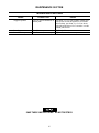
TROUBLESHOOTING GUIDE
Trouble
Probable Cause Solution
Sluggish operation Dirt or oil gum accumulation on
internal parts
Pour about 3 cc of a clean, suitable, cleaning solu-
tion into the air inlet and operate for 30 seconds.
After flushing, pour about 3 cc of oil into the air
inlet and operate the tool for 5 seconds to coat the
internal parts with oil.
Loss of power Worn Valve Replace the Valve.
Loss of efficiency Worn Piston and/or accessory Replace Piston and or accessory.
SAVE THESE INSTRUCTIONS. DO NOT DESTROY.
Page is loading ...
-
 1
1
-
 2
2
-
 3
3
-
 4
4
-
 5
5
-
 6
6
-
 7
7
-
 8
8
-
 9
9
-
 10
10
-
 11
11
-
 12
12
-
 13
13
-
 14
14
-
 15
15
-
 16
16
-
 17
17
-
 18
18
-
 19
19
-
 20
20
-
 21
21
-
 22
22
-
 23
23
-
 24
24
-
 25
25
-
 26
26
-
 27
27


Ingersoll-Rand AVC26 Operation and Maintenance Manual
- Category
- Power tools
- Type
- Operation and Maintenance Manual
Ask a question and I''ll find the answer in the document
Finding information in a document is now easier with AI
in other languages
- français: Ingersoll-Rand AVC26
- español: Ingersoll-Rand AVC26
- português: Ingersoll-Rand AVC26
Related papers
-
Ingersoll-Rand Impact Driver 132 User manual
-
-
-
-
-
-
Ingersoll Rand 121-EU User manual
-
-
-
Other documents
-
Facom V.331AH User manual
-
Husky H4630 Operating instructions
-
-
-
Matco Tools MT1724 Operating Instructions Manual
-
-
-
Stanley STMT74840-840 User manual
-
ATD Tools ATD-2150 User manual
-