Page is loading ...

INSTALLATION
1
. Carefully unpack switch and remove any packing material from lower housing.
T
rim the vane at the appropriate mark for the size of pipe being used. See
a
ctuation/deactuation chart. CAUTION: Mechanical shock or vibration can cause
permanent damage to the reed switch. Take care to avoid dropping the unit on hard
surfaces or impacting the switch assembly.
2. Apply pipe thread sealant tape or pipe thread sealant to the 1/2˝ male NPT
m
ounting threads and install switch in the system piping with the arrow on side
p
ointing in the direction of flow.
3. Connect wiring in accordance with local electrical codes.
4. Inductive, capacitive and lamp loads can all create conditions harmful to the reed
switch.
A) Inductive loads can be caused by electromagnetic relays, electromagnetic
solenoids and electromagnetic counters, all with inductive components as the
circuit load.
B) Capacitive loads can be caused by capacitors connected in series with or
parallel to the reed switch. In a closed circuit the cable length (150 ft. or more) to
the switch can introduce a capacitance.
C) Lamp loads can be caused by switching lamp filaments which have low cold
resistance.
In addition to these causes, exceeding any of the maximum electrical ratings can
lead to premature or immediate failure. This includes inrush and surge currents
greater than the maximum switching current. Use caution when evaluating system
loads and current. To accommodate these conditions, see diagrams on the reverse
which depict possible solutions.
5. After installation, set the switch action to NO
(normally open) or NC (normally
closed). Normally closed contacts open and normally open contacts close when
increasing flow actuates the reed switch. To change, loosen, but do not remove,
the two screws on the top cap. Slide the reed switch assembly to expose the switch
action selected. Tighten screws when adjustment is complete.
MAINTENANCE/REPAIR
Upon final installation of the Model V10, no routine maintenance is required. The
Model V10 is not field serviceable and should be returned if repair is needed. Field
repair should not be attempted and may void warranty.
WARRANTY/RETURN
Refer to “Terms and Conditions of Sales” in our catalog and on our website.
Contact customer service to receive a Return Goods Authorization number before
shipping the product back for repair. Be sure to include a brief description of the
problem plus any additional application notes.
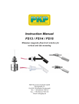
Model V10 Flotect
®
Mini-Size Flow Switch
Bulletin E-26
Cold Water Flow Rates
Approximate actuation/deactuation
GPM upper, LPM lower
Specifications – Installation and Operating Instructions
SPECIFICATIONS
Service: Compatible gases or liquids.
Wetted Materials:
Vane: 301 SS;
Body: Brass or 303 SS;
Pin and spring: 301 SS, 302 SS and 316 SS;
M
agnet: Ceramic 8.
T
emperature Limit: 200°F (93°C).
P
ressure Limit: Brass body: 1000 psig (69 bar); 303 SS body: 2000 psig (138
bar).
Enclosure Rating: Weatherproof, meets NEMA 4X (IP66).
Switch Type: SPST hermetically sealed reed switch. Field adjustable for
normally open or normally closed.
Electrical Rating: 0.5 A @ 120 VAC; 1.5 A @ 24 VDC res.; 0.001 A @ 200 VDC
res.
Electrical Connections: 18 AWG, 19˝ (483 mm) long, PVC jacket. Rated 221°F
(105°C).
Process Connection: 1/2˝ male NPT standard. Contact factory for other options.
Mounting Orientation: Switch can be installed in any position but the
actuation/deactuation flow rates are based on horizontal pipe runs and are
nominal values.
Set Point Adjustment: Vane is trimmable.
Weight: 5.5 oz (0.16 kg).
Agency Approvals: CE, cUR, UR and CSA.
Switch Enclosure: Nylon.
Air Flow Rates
Approximate actuation/deactuation
SCFM upper, LPM lower
Pipe
1/2˝
3/4˝
1˝
1-1/4˝
1-1/2˝
2˝
N.O.
2.6/2.3
9.8/8.7
3.1/2.7
11.7/10.2
4.8/4.5
18.2/17
6.2/5.6
23.5/21.2
8.2/7.7
31/29.1
9.5/9.1
36/34.4
Trim
L
J
H
E
C
Full
N.C.
2.6/2.5
9.8/9.5
3.1/2.8
11.7/10.6
4.8/4.4
18.2/16.7
6.1/5.6
23.1/21.2
8.2/7.7
31/29.1
9.5/9
36/34.1
Pipe
1/2˝
3/4˝
1˝
1-1/4˝
1-1/2˝
2˝
Trim
L
J
H
E
C
Full
N.O.
10.3/8.8
291.7/250
13/11.6
368.3/328
19.2/17.6
543.3/498
24.8/22.2
701.7/628
33.4/31.2
946.7/883
50.2/48.4
1422/1370
N.C.
10.2/9.2
288/260
12.9/11.6
365/328
18.9/17.6
535/498
24.5/22.5
693/637
33/30.6
935/867
50.2/47.7
1422/1352
L
OWER
B
ODY
7/8 HEX
1
/2 MALE
N
PT
V
ANE
N
ORMALLY OPEN
P
OSITION
N
ORMALLY CLOSED
P
OSITION
2-3/8
[61.11]
2-7/8
[73.07]
1/4 [6.35]
TRAVEL TO
NORMALLY
CLOSED
POSITION
1
[
25.40]
4 [101.6]
2-7/8 [73.07]
18 AWG LEAD WIRES
19˝ [482.6] LONG
CABLE
W.E. ANDERSON,
A DIV. OF DWYER INSTRUMENTS, INC.
P.O. BOX 373 • MICHIGAN CITY, INDIANA 46360, U.S.A.
Phone: 219/879-8000
Fax: 219/872-9057
www.dwyer-inst.com
e-mail: [email protected]

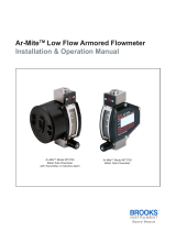
REED SWITCH PROTECTION CIRCUIT INFORMATION BULLETIN
R
EAD INFORMATION BELOW BEFORE INSTALLING YOUR NEW REED SWITCH CONTROL!
E
xceeding the current capacity of this Reed Switch control may cause FAULTY OPERATION!
B
e aware of the inductive and capacitive or lamp loads you may be placing on
y
ou Reed Switch Control. The circuits below outline possible solutions to preventing overloads due to inrush or surge currents exceeding maximum or when the switch current
a
nd product of the inductive back EMF exceed the switch’s power rating. Also the circuit for prevention of overload when switching filament lamps (low “cold” resistance) is
outlined below. Failure to follow these measures to protect Reed Switch Contacts may cause the contacts to weld together or result in premature wear.
Possible Circuit Solutions Indicated by Dashed Lines
I
nductive Loads
P
ossible causes –
An electromagnetic relay, electromagnetic solenoid,
electromagnetic counter with inductive component as
circuit load.
C
apacitive Loads
Possible causes –
A capacitor connected in series or parallel with Reed
Switch control. In a closed circuit, a cable length (usually
greater than 50m [162.5 ft.]) used to connect reed switch
may also introduce static capacitance.
Lamp Loads
Possible causes –
A tungsten filament lamp load.
Do not subject reed switch control to excessive shock and
vibration, including:
• Bending or placing force loads on reed
switch housing
• Over-torquing fittings on reed switch housing
• Placing pull-out force on load wires
DIODE SUPPRESSION
DIODE
I
NDUCTIVE
L
OAD
PIV DIODE > V
R
EED
S
WITCH
R
EED
S
WITCH
USED IN
AC CIRCUITS
VARISTER
V
ARISTER PROTECTION
INDUCTIVE
LOAD
R
C SUPPRESSION
R
C
I
NDUCTIVE PROTECTION FOR
C
ABLE LENGTH CAPACITANCE
LOAD
REED
SWITCH
Cable Length
over 50 meters
[162.5 ft.]
REED
SWITCH
R
ESISTOR PROTECTION
F
OR CAPACITIVE LOAD
S
URGE LIMITER FOR
C
APACITANCE IN SERIES
REED
SWITCH
CURRENT LIMITING RESISTOR
IN SERIES
CURRENT LIMITING RESISTOR
IN PARALLEL
REED
SWITCH
REED
SWITCH
INDUCTIVE
L
OAD
R
EED
SWITCH
S
WITCH
[uf]
10
C
R
10*I
(1+50/E)
S
WITCH
2
C
LOAD
S
WITCH
SWITCH
L
OAD
C
R
L =0.5~5 mH
P
+V
R
A
P
L
R
A
+V
R = 50~500 Ohms
R
B
P
L
L = 0.5~5 mH
P
+V
R
L
R
R
V-0.12 R
L
2
+V R
L
5R > R
L
R
W.E. ANDERSON,
A DIV. OF DWYER INSTRUMENTS, INC.
P.O. BOX 373 • MICHIGAN CITY, INDIANA 46360, U.S.A.
©Copyright 2015 Dwyer Instruments, Inc.
Phone: 219/879-8000
Fax: 219/872-9057
www.dwyer-inst.com
e-mail: [email protected]
Printed in U.S.A. 2/15 FR# 440783-00 Rev. 10
/