Page is loading ...

OPERATING INSTRUCTIONS
Utility Amplifier
CAUTION: Risks of electrical shockÑDO NOT OPEN
CAUTION: To reduce the risk of electric shock, do not remove cover. No
user serviceable parts inside. Refer Servicing to qualified service
personnel.
Intended to alert the user to the presence of uninsulated
"dangerous voltage" within the product's enclosure that may be
of sufficient magnitude to constitute a risk of electric shock to
persons.
Intended to alert the user to the presence of important operating
and maintenance (servicing) instructions in the literature
accompanying the product.
UA
ª
35T II

FEATURES
¥ 35 watts into 4 ohms
¥ Mic/page inputs (screw terminals)
¥ Mic/page select switch
¥ Dedicated program input (screw terminals
and RCA jacks)
¥ Bass and treble controls
¥ Mic/page level control
¥ AUX level control
¥ Direct 4 ohms output (screw terminals)
¥ Completely isolated 8 ohms, 25 volt, and
70 volt outputs (screw terminals)
¥ Shelf-top or wall-mountable
chassis
DESCRIPTION
The UAª 35T II is a high quality utility amplifier ideally
suited for varying installation requirements. It produces 35 watts
into 4 ohms and 8 ohms direct connections plus a broad range
of line amplification. Level controls are provided for mic/page
and AUX. The mic/page input is accessed via screw terminals or
RCA jacks. Bass and treble controls are functional on the total
system (mic/page/AUX). When a signal is present at the
mic/page input, the AUX input is muted. This feature is internally
defeatable when required.
Twenty-five and seventy volt line output capability is
standard equipment, and the unit is packaged for shelf or wall
mounting convenience. The user-friendly control layout, coupled
with state-of-the-art circuit design, ensure reliable long-term
operation and smooth trouble-free installation.
WALL OR SHELF MOUNTING
The UA 35T II can be mounted on a vertical or horizon-
tal surface using the brackets formed on the bottom panel. For
mounting on a wooden or paneled surface, use No. 6 x 1/2" or
larger wood screws. For mounting onto a masonry or drywall
type surface, use fasteners that are designed for this purpose.
WARNING!
DO NOT ATTEMPT TO INSTALL THIS UNIT WHILE IT OR
ANY CONNECTING UNITS ARE POWERED ON. RISK OF
ELECTRICAL SHOCK EXISTS IF ALL UNITS ARE NOT
POWERED OFF DURING INSTALLATION. TO PREVENT
ELECTRICAL SHOCK OR FIRE HAZARD, DO NOT EXPOSE
THIS APPLIANCE TO RAIN OR MOISTURE.
MIC/PAGE LEVEL CONTROL (1)
Controls the signal level at the mic/page inputs. (See mic/page
switch (7).)
AUX LEVEL CONTROL (2)
Controls the signal level at the AUX inputs.
HIGH EQ CONTROL (TREBLE) (3)
Active equalization control that adjusts the high frequency
response. Clockwise rotation boosts highs while counterclock-
wise rotation provides a cut (reduction) of the high frequencies
(±10 dB).
LOW EQ CONTROL (BASS) (4)
Active equalization control that adjusts the low frequency
response. Clockwise rotation boosts lows while counterclockwise
rotation provides a cut (reduction) of the low frequencies (±10
dB).
AUX IN (5)
Accepts signals from other sources, such as another mixer or
background music source. Signal level at this input is controlled
by the AUX level control and is fed to the Master output.
POWER LED (6)
Green LED illuminates when power is being supplied to the unit.
1
7
8
9
5
4
6
3
2
2

MIC/PAGE SWITCH (7)
Selects between mic and page input. The page selection
provides internal pad, converting this input to line level for page
applications.
INPUTS (8)
Low Z mic/page inputs are provided via screw terminals. Screw
terminal AUX inputs are paralleled with AUX RCA jacks. (See
AUX IN (5).)
OUTPUTS (9)
A direct output, as well as several transformer outputs, are
provided to allow the proper interface between the amplifier and
the speaker system. The direct output allows direct connection to
a 4 ohms speaker system. Connect the speaker (or speakers)
from the GND terminal to the 4 ohms terminal. For 8 ohms
speaker systems, connect between the COM terminal and the 8
ohms terminal.
25 V and 70 V outputs are also provided for Òconstant volt-
ageÓ speaker distribution systems. The 25 V and 70 V output
connection is between the COM terminal and the 25 V or 70 V
terminal.
FUSE (10)
The fuse is located within the cap of the fuseholder. It the fuse
should fail, IT MUST BE REPLACED WITH THE SAME TYPE
AND VALUE IN ORDER TO AVOID DAMAGE TO
THE EQUIPMENT AND TO PREVENT VOIDING THE
WARRANTY. If the amp repeatedly blows fuses, it should
be taken to a qualified service center for repair.
WARNING: THE FUSE SHOULD ONLY BE REPLACED
WHEN THE POWER CORD HAS BEEN DISCONNECTED
FROM ITS POWER SOURCE.
AC LINE CORD SOCKET (11)
Provided to accept the removable AC line cord. Connect only to
proper source--see back panel markings.
POWER SWITCH (12)
Used to turn AC mains power on or off.
3
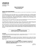
BLOCK DIAGRAM
Level
Level
Muting
Sense
EQ
AMP
Sum
Mic/Page
Selector
Switch
Mic/Page
Barrier
Strip
Aux 1
Barrier
Strip
Transformer
Barrier
Strip
GND
4W
COM
8W
25V
70V
DDT
11
10
12

4
70V ÒConstant VoltageÓ Distribution System
OUTPUTS 35 W RMS
GND 4W COM 8W 25V 70V
(12V)
(17V)
WIRING DIAGRAM
OUTPUT POWER:
35 watts RMS
POWER BANDWIDTH:
Aux 50 Hz - 20 kHz .6% THD
Mic 50 Hz - 20 kHz .8% THD
Page 50 Hz - 20 kHz .6% THD
FREQUENECY RESPONSE:
Aux 50 Hz - 20 kHz +0, -2 dB
Mic 50 Hz - 20 kHz +0, -2 dB
Page 50 Hz - 20 kHz +0, -2 dB
THD (1 kHz):
Aux <.05%
Mic <.2%
Page <.2%
S/N RATIO (22 kHz BW):
Tone controls flat/input control max
Aux 85 dB (50 ohm input)
Mic 58 dB (150 ohm input)
Page 58 dB (680 ohm input)
TONE CONTROLS:
Bass +/- 10 dB @ 100 Hz
Treble +/- 10 dB @ 10 kHz
INPUTS:
Aux Input: Dual RCA phono jacks, summed
Mic/Page Input: Screw terminal input switchable between
mic/page
INPUT SENSITIVITY:
Aux Input: 100mV @ 10K ohms
Mic Input: 1mV @ 1K ohms
Page Input: 120mV @ 5K ohms
OUTPUTS:
4 ohms, 8 ohms, 25 V, 70 V
OUTPUT REGULATION:
Less than 0.5 dB, no load to full load
CONTROLS:
1 Aux input gain control, 1 mic/page gain control, 1 bass control,
1 treble control, 1 mic/page select switch
INDICATORS:
Power LED
PROTECTION:
Built-in, with AC line fuse
POWER CONSUMPTION:
120 volts AC, 60 Hz, 100 watts
DIMENSIONS:
4.25" H x 8.25" W x 13.625" D
WEIGHT:
11.5 pounds
COLOR:
Gray
OTHER FEATURES:
Mic/page input has precedence over the Aux input (defeatable)
UA 35T Specifications

5
IMPORTANT SAFETY INSTRUCTIONS
WARNING: When using electric products, basic cautions should always be followed. including the following.
1. Read all safety and operating instructions before using this product.
2. All safety and operating instructions should be retained for future reference.
3. Obey all cautions in the operating instructions and on the back of the unit.
4. All operating instructions should be followed.
5. This product should not be used near water, i.e., a bathtub, sink, swimming pool, wet basement, etc.
6. This product should be located so that its position does not interfere with its proper ventilation. It should not be placed flat against a wall
or placed in a built-in enclosure that will impede the flow of cooling air.
7. This product should not be placed near a source of heat such as a stove, radiator, or another heat producing amplifier.
S. Connect only to a power supply of the type marked on the unit adJacent to the power supply cord.
9. Never break off the ground pin on the power supply cord. For more information on grounding, write
for our free booklet ÒShock Hazard and Grounding."
10. Power supply cords should always be handled carefully. Never walk or place equipment on power supply cords. Periodically check cords for
cuts or signs of stress, especially at the plug and the point where the cord exits the unit.
I I. The power supply cord should be unplugged when the unit is to be unused for long periods of time.
I 2. If this product is to be mounted in an equipment rack, rear support should be provided.
13. Metal parts can be cleaned with a damp rag. The vinyl covering used on some units can be cleaned with a damp rag or an ammonia-based
household cleaner if necessary. Disconnect unit from power supply before cleaning.
14. Care should be taken so that objects do not fall and liquids are not spilled into the unit through the ventilation holes or any other openings.
15. This unit should be checked by a qualified service technician if:
a. The power supply cord or plug has been damaged.
b. Anything has fallen or been spilled into the unit.
c. The unit does not operate correctly.
d. The unit has been dropped or the enclosure damaged.
16. The user should not attempt to service this equipment. All service work should]d be done by a qualified service technician.
17. This product should be used only with a cart or stand that is recommended by Peavey Electronics.
18. Exposure to extremely high noise ]levels may cause a permanent hearing loss. individuals vary considerably in susceptibility to noise induced
hearing loss, but nearly everyone will lose some hearing if exposed to sufficiently intense noise for a sufficient time. The U.S. GovernmentÕs
Occupational Safety and Health Administration (OSHA) has specified the following permissible noise level exposures.
Duration Per Day In Hours Sound Level dBA, Slow Response
890
692
495
397
2 100
1 1/2 102
1 105
1/2 110
1/4 or less 115
According to OSHA, any exposure in excess of the above permissible limits could result in some hearing loss. Ear plugs or protectors h1 the
ear canal]s or over the ears must be worn when operating this amplification system in order to prevent a permanent hearing loss if exposure is
in excess of the limits as set forth above. To ensure against potentially dangerous exposure to high Sound pressure levels. it is recommended
that all persons exposed to equipment capable of producing high sound pressure levels such as this amplification system be protected by hear-
ing protectors while this unit is in operation.
SAVE THESE INSTRUCTIONS!

Features and specifications subject to change without notice.
Peavey Electrontics Corporation / 711 A Street, MS 39301 / U.S.A. / (601) 483-5376 / Fax 486-1154
© 1997 Printed in U.S.A. 10/97
80304366
/