
Grass Trimmer/Brush Cutter
Operator's Manual
MODEL SRM-410U
X750-012 31 6
X750 216-3706
Printed in Japan 1401Ek 1114 ES
WARNING
Users of this equipment risk injury to themselves and others if the unit is used im-
properly and/or safety precautions are not followed. ECHO provides an operator’s
manual and a safety manual. Both must be read and understood for proper and safe
operation. Failure to do so could result in serious injury.

2
Copyright© 2009 By ECHO, Incorporated
All Rights Reserved.
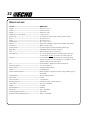
TABLE OF CONTENTS
Introduction ..........................................................................2
- The Operator's Manual .................................................2
- The Safety manual .......................................................2
Safety ...................................................................................3
- Manual Safety Symbols and Important Information ...3
- International Symbols ..................................................3
- Personal Condition and Safety Equipment ..................3
- Equipment ....................................................................6
Emission Control .................................................................6
Description ...........................................................................7
Contents ...............................................................................9
Assembly............................................................................10
- Drive Shaft / Power Head ..........................................10
- Blade Installation .......................................................10
- U-Handle Installation .................................................12
- Balance and Adjust Unit ............................................13
- Optional Nylon Head Installation ..............................14
- Operating Instructions Nylon Line ............................15
Operation ............................................................................16
- Blade Selection ..........................................................16
- Fuel ............................................................................18
- Starting Cold Engine ..................................................20
- Starting Warm Engine ................................................21
- Stopping Engine .........................................................21
Maintenance .......................................................................22
- Skill Levels ................................................................22
- Maintenance Intervals ................................................22
- Air Filter .....................................................................23
- Fuel Filter ...................................................................24
- Spark Plug ..................................................................24
- Cooling System ..........................................................25
- Exhaust System ..........................................................25
- Carburetor Adjustment ...............................................27
- High altitude Operation ...........................................27
- Lubrication .................................................................28
- Sharpening Metal Blades ...........................................29
Troubleshooting .................................................................30
Storage ...............................................................................31
Specifi cations .....................................................................32
Warranty Statements ..........................................................33
Specifi cations, descriptions and illustrative material in
this literature are as accurate as known at the time of
publication, but are subject to change without notice.
Illustrations may include optional equipment and acces-
sories, and may not include all standard equipment.
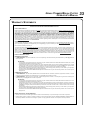
INTRODUCTION
Welcome to the ECHO family. is ECHO product was designed and manufactured to provide long life and on-the-job-
dependability. Read and understand this manual and the SAFETY MANUAL. You will nd both easy to use and full of
helpful operations tips and SAFETY messages.
THE OPERATOR'S MANUAL
Keep it in a safe place for future reference. Contains speci cations and
information for safety, operation, maintenance, storage, and assembly
speci c to this product.
THE SAFETY MANUAL
Keep it in a safe place for future reference. Explains possible hazards
and the measures you should take to insure safe operation.

GRASS TRIMMER/BRUSH CUTTER
OPERATOR'S MANUAL
3
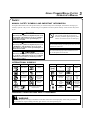
INTERNATIONAL SYMBOLS
SAFETY
MANUAL
SAFETY SYMBOLS AND IMPORTANT INFORMATION
Throughout this manual and on the product itself, you will fi nd safety alerts and helpful, informational messages pre-
ceded by symbols or key words. The following is an explanation of those symbols and key words and what they mean
to you.
Hot
Surface
Carburetor Adjust-
ment
- Idle speed
Carburetor Adjust-
ment
- High speed
mixture
DESCRIPTION
SYMBOLSYMBOL
"WARNING, SEE OP-
ERATOR'S MANUAL
Wear eye, ear
and head protec-
tion
Emergency
Stop
Fuel and oil
mixture
Finger Severing
Carburetor Adjust-
ment
- Low speed
mixture
Primer
Bulb
Ignition
ON/
OFF
Wear hand and
foot protection
Safety/Alert
Keep bystanders and helpers
away 15 m (50 ft.).
DO NOT smoke
near fuel.
DO NOT allow
ames or sparks
near fuel.
DESCRIPTION
SYMBOL
DESCRIPTION
SYMBOL
DESCRIPTION
Choke Control
"Cold Start"
Position
(Choke Closed)
Choke Control
"Run"
Position
(Choke Open)
Do not use
blades. String
line only
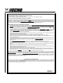
PERSONAL CONDITION AND SAFETY EQUIPMENT
WARNING
Users of this product risk injury to themselves and others if the unit is used improperly and/or safety precautions
are not followed. Proper clothing and safety gear must be worn when operating unit.
WARNING
The safety alert symbol accompanied by the word
“WARNING” calls attention to an act or condi-
tion which CAN lead to serious personal injury or
death if not avoided.
CIRCLE AND SLASH SYMBOL
This symbol means the specifi c action
shown is prohibited. Ignoring these prohi-
bitions can result in serious or fatal injury.
CAUTION
The safety alert symbol accompanied by the word
“CAUTION” calls attention to an act or condition
which may lead to minor or moderate personal
injury if not avoided.
NOTE
This enclosed message provides tips for use, care and
maintenance of the unit.
IMPORTANT
The enclosed message provides information neces-
sary for the protection of the unit.
DANGER
The safety alert symbol accompanied by the word
“DANGER” calls attention to an act or condition
which WILL lead to serious personal injury or
death if not avoided.

4
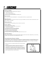
Physical Condition
Your judgment and physical dexterity may not be good:
• if you are tired or sick,
• if you are taking medication,
• if you have taken alcohol or drugs.
Operate unit only if you are physically and mentally well.
Eye Protection
Wear eye protection that meets ANSI Z87.1 or CE requirements whenever you operate the unit.
Hand Protection
Wear no-slip, heavy-duty work gloves to improve your grip on the handle. Gloves also reduce the transmission of ma-
chine vibration to your hands.
Hearing Protection
ECHO recommends wearing hearing protection whenever unit is used.
Proper Clothing
Wear snug fi tting, durable clothing;
• Pants should have long legs, shirts with long sleeves.
• DO NOT WEAR SHORTS,
• DO NOT WEAR TIES, SCARFS, JEWELRY.
Wear protective hair covering to contain long hair.
Wear sturdy work shoes with nonskid soles;
• DO NOT WEAR OPEN TOED SHOES,
• DO NOT OPERATE UNIT BAREFOOTED.
Keep long hair away from engine and air intake. Retain hair with cap or net.
Hot Humid Weather
Heavy protective clothing can increase operator fatigue which may lead to heat stroke. Schedule heavy work for early
morning or late afternoon hours when temperatures are cooler.
Extended Operation/Extreme Conditions
It is believed that a condition called Raynaud’s Phenomenon, which affects the fi ngers of certain individuals, may be
brought about by exposure to vibration and cold. Exposure to vibration and cold may cause tingling and burning sensa-
tions, followed by loss of color and numbness in the fi ngers. The following precautions are strongly recommended,
because the minimum exposure, which might trigger the ailment, is unknown.
• Keep your body warm, especially the head, neck, feet, ankles, hands,
and wrists.
• Maintain good blood circulation by performing vigorous arm exer-
cises during frequent work breaks, and also by not smoking.
• Limit the hours of operation. Try to fi ll each day with jobs where op-
erating the unit or other hand-held power equipment is not required.
• If you experience discomfort, redness, and swelling of the fi ngers fol-
lowed by whitening and loss of feeling, consult your physician before
further exposing yourself to cold and vibration.

GRASS TRIMMER/BRUSH CUTTER
OPERATOR'S MANUAL
5
DANGER
Do not operate this product indoors or in inadequately ventilated
areas. Engine exhaust contains poisonous emissions and can cause
serious injury or death.
Read the Manuals
• Provide all users of this equipment with the Operator’s Manual and
Safety Manual for instructions on Safe Operation.
Clear the Work Area
• Spectators and fellow workers must be warned, and children and
animals prevented from coming nearer than 15 m (50 ft.) while the
unit is in use.
Keep a Firm Grip
• Always use both hands on the handles. Do not operate one-handed.
Always hold the unit with the fi ngers and thumbs encircling the
handles.
Keep a Solid Stance
• Maintain footing and balance at all times. Do not stand on slippery,
uneven or unstable surfaces. Do not work in odd positions or on lad-
ders. Do not over reach.
Avoid Hot Surfaces
• Keep exhaust area clear of fl ammable debris. Avoid contact during
and immediately after operation.
Repetitive Stress Injuries
It is believed that overusing the muscles and tendons of the fi ngers, hands, arms, and shoulders may cause soreness,
swelling, numbness, weakness, and extreme pain in those areas. Certain repetitive hand activities may put you at a high
risk for developing a Repetitive Stress Injury (RSI). An extreme RSI condition is Carpal Tunnel Syndrome (CTS), which
could occur when your wrist swells and squeezes a vital nerve that runs through the area. Some believe that prolonged
exposure to vibration may contribute to CTS. CTS can cause severe pain for months or even years.
To reduce the risk of RSI/CTS, do the following:
• Avoid using your wrist in a bent, extended, or twisted position.
Instead try to maintain a straight wrist position. Also, when grasping,
use your whole hand, not just the thumb and index fi nger.
• Take periodic breaks to minimize repetition and rest your hands.
• Reduce the speed and force with which you do the repetitive move-
ment.
• Do exercise to strengthen the hand and arm muscles.
• Immediately stop using all power equipment and consult a doctor if
you feel tingling, numbness, or pain in the fi ngers, hands, wrists, or
arms. The sooner RSI/CTS is diagnosed, the more likely permanent
nerve and muscle damage can be prevented.

6
EQUIPMENT
WARNING
Use only ECHO approved attachments. Serious injury may result from the use of a non-approved attachment com-
bination. ECHO, INC. will not be responsible for the failure of cutting devices, attachments or accessories which
have not been tested and approved by ECHO. Read and comply with all safety instructions listed in this manual and
safety manual.
• Check unit for loose/missing nuts, bolts, and screws. Tighten and/or replace as needed.
• Inspect shield for damage and ensure that the cut-off knife is securely in place. Replace if either is damaged or miss-
ing.
• Check that the cutting attachment is fi rmly attached and in safe operating condition.
• Check that front loop handle and shoulder strap/ or shoulder/waist harness are adjusted for safe, comfortable opera-
tion. See Assembly Section for proper adjustment.
WARNING
Moving parts can amputate fi ngers or cause severe injuries. Keep hands, clothing and loose objects away from all
openings.
• ALWAYS stop engine, disconnect spark plug, and make sure all moving parts have come to a complete stop
before removing obstructions, clearing debris, or servicing unit.
• DO NOT start or operate unit unless all guards and protective covers are properly assembled to unit.
• NEVER reach into any opening while the engine is running. Moving parts may not be visible through openings.
WARNING
Check fuel system for leaks due to fuel tank damage, especially if the unit is dropped. If damage or leaks are found,
do not use unit, otherwise serious personal injury or property damage may occur. Have unit repaired by an authorized
servicing dealer before using.
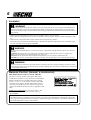
An Emission Control Label is located on the engine. ( is
is an EXAMPLE ONLY, information on label varies by
engine FAMILY).
EMISSION CONTROL (EXHAUST & EVAPORATIVE)
EPA 2010 and Later and/or C.A.R.B. TIER III
PRODUCT EMISSION DURABILITY (EMISSION COMPLIANCE PERIOD)
e 300 hour emission compliance period is the time span selected by the manufacturer certifying the engine emis-
sions output meets applicable emissions regulations, provided that approved maintenance procedures are followed as
listed in the Maintenance Section of this manual.
e emission control system for the engine is EM (engine
modi cation) and, if the second to last character of the Engine
Family on the Emission Control Information label (sample
below) is “C”, “K”, or “T”, the emission control system is EM
and TWC (3-way catalyst). e fuel tank/fuel line emission
control system is EVAP (evaporative emissions). Evaporative
emissions for California models may only be applicable to fuel
tanks.

GRASS TRIMMER/BRUSH CUTTER
OPERATOR'S MANUAL
7
P/N 89031749030
P/N X505002310
Hot Decal (near muffl er)
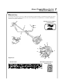
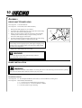
DESCRIPTION
Locate these safety decals on your unit. Make sure the decals are legible and that you understand and follow the instruc-
tions on them. If a decal cannot be read, a new one can be ordered from your ECHO dealer. See PARTS ORDERING
instructions for specifi c information.
P/N 89011841031
Metal Debris Shield Decal
Shaft Decal
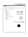
1
2
3
4
5
6
7
8
9
10
11
13
14
15
16
17
18
12
19
20

8
1. POWER HEAD - Includes the Engine, Clutch, Fuel System, Ignition System and Recoil Starter.
2. THROTTLE TRIGGER LOCKOUT - This lever must be held during starting. Operation of the throttle trigger is
prevented unless throttle trigger lockout lever is engaged.
3. STOP SWITCH - "SLIDE SWITCH" mounted on top of the Throttle Trigger Housing. Move switch FORWARD
to RUN, BACK to STOP.
4. THROTTLE TRIGGER - Controls engine speed. Spring loaded to return to idle when released. During accelera-
tion, press trigger gradually for best operating technique.
5. DRIVE SHAFT ASSEMBLY - Includes the Gear Housing assembly, metal drive shaft and Safety Decal.
6. U-HANDLE - Required for metal blade operation.
7. HIP PAD - Used to protect hip/leg and clothing when using U-handle equipped unit.
8. SHOULDER HARNESS- An adjustable strap that suspends the unit from the operator. Using the strap reduces
operator fatigue.
9. BLADE - Circular blade for grass, weed or brush cutting applications. Harness, metal shield & U-handles required
for blade operation.
10. METAL BLADE SHIELD - Required when unit is equipped with blades. Do not operate unit without shield.
11. SPARK PLUG - Provides spark to ignite fuel mixture.
12. ARM REST - Provides arm rest during operation and protects arm from the hot engine.
13. SPARK ARRESTOR MUFFLER OR SPARK ARRESTOR MUFFLER WITH CATALYST -The muffl er or
catalytic muffl er controls exhaust noise and emission. The spark arrestor screen prevents hot, glowing particles of
carbon from leaving the muffl er. Keep exhaust area clear of fl ammable debris.
14. FUEL TANK - Contains fuel and fuel fi lter.
15. RECOIL STARTER HANDLE - Pull handle slowly until starter engages, then quickly and fi rmly. When engine
starts, return handle slowly. DO NOT let handle snap back or damage to unit will occur.
16. FUEL TANK CAP - Covers and seals fuel tank opening.
17. PURGE BULB - Pumping purge bulb before starting engine draws fresh fuel from the fuel tank, purging air from
the carburetor. Pump purge bulb until fuel is visible and fl ows freely in the clear fuel tank return line. Pump purge
bulb an additional 4 or 5 times.
18. AIR CLEANER - Contains replaceable fi lter element.
19. CHOKE - The choke control is located at the rear of the air cleaner housing. Move choke lever to Cold Start
(
) to close choke for cold start. Move choke lever to "Run" ( ) position to open choke.
20. DECOMPRESSION BUTTON - Push button to assist starting. Automatically resets after engine starts and runs.

GRASS TRIMMER/BRUSH CUTTER
OPERATOR'S MANUAL
9
CONTENTS
The ECHO product you purchased has been factory pre-assembled for your convenience. Due to packaging restrictions,
shield installation and other assembly may be necessary.
After opening the carton, check for damage. Immediately notify your retailer or ECHO Dealer of damaged or missing
parts. Use the contents list to check for missing parts.
___ 1- Power Head
___ 1- Drive Shaft Assembly
___ 1- Plastic Bag (co-pack)
__ - 1, Operator's Manual
__ - 1, Safety Manual
__ - 1, Warranty Registration Card
___ - 1, Tool Bag
___ --1, wrench 17x19 mm
___ --1, locking tool
___ --1, 8 x 10 mm Open End Wrench
___ --1, 4 mm Hexagon Wrench
___ - 1, Safety Glasses
___ - 1, Plastic Bag
___ --3, 5 mm x 10 mm screws (shield mount)
___ --2, 5 mm x 10 mm screws (bracket to shield)
___ --4, 5 mm nuts
___ --1, metal shield
___ --1, bracket
___ - 1, Shoulder Harness w/hip pad
___ - 10,
Cotter Pins
____ - 1, Blade

10
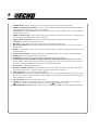
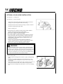
BLADE INSTALLATION
WARNING
You must install the U-Handle and all Blade Conversion parts shown in the following instructions before operating
this unit with a metal blade, otherwise serious injury may result.
Install Metal Shield
Tools Required: 8 x 10 mm Open-end Wrench, Screwdriver, 17x19 mm Wrench, Locking Tool
Parts Required: Metal Shield, Shield Bracket,
3 - 5 x 10 mm screws (metal shield to gear housing).
2 - 5 x 10 mm screws, 2 - 5 mm nuts (bracket to shield).
2 - 5 mm nuts (bracket to gear housing).
A
B
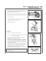
ASSEMBLY
DRIVE
SHAFT/POWER HEAD
Tools Required: 4 mm Hex Wrench
Parts Required: Power Head, Drive Shaft Assembly
1. Stand power head upright on a level surface.
2. Loosen the drive shaft clamp bolt (A) at engine drive shaft clamp,
and remove drive shaft locating bolt (B).
3. Remove protective plastic cap from end of drive shaft assembly.
Carefully fi t driveshaft assembly to engine making sure that
inner drive shaft engages clutch mount.
4. Turn drive shaft housing until locating hole lines up with locating
hole in clamp and install drive shaft locating bolt (B).
NOTE
Gear housing must be aligned properly with engine. Aligning center
locating hole in driveshaft housing with center drive shaft bolt (B)
provides correct alignment.
5. Tighten drive shaft clamp bolt (A) securely.
WARNING
Never start engine without driveshaft assembly installed.
This could result in serious injury.

GRASS TRIMMER/BRUSH CUTTER
OPERATOR'S MANUAL
11
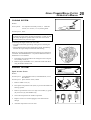
1. Align hole in upper plate (D) with notch in gear housing (E), and
insert locking tool to prevent splined shaft from turning. Arrow on
gear housing fl ange points to notch location.
2. Remove split pin (F), L.H. blade nut (G), lower plate (H), and up-
per plate (D) from PTO shaft. Turn blade nut clockwise to remove.
3. Remove locking tool.
4. Loosely attach bracket (I) to shield (J) and attach shield to bottom
of gear housing (E) with hardware provided.
5. Tighten all shield hardware.
J
I
E
H
G
F
D
E
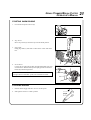
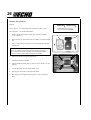
Install Blade
Tools Required: Locking Tool, 17x19 mm Wrench.
Parts Required: Upper Plat, Lower Plate, 10 mm Nut w/L.H. threads,
2 x 25 mm Cotter Pin, Blade.
1. Install upper plate (D) on splined PTO shaft, pilot side down.
Blade installation requires Upper Plate (D).
2. Install Blade (K) on upper plate pilot. Blades must be installed so
that rotation arrow on blade matches rotation of unit: teeth toward
direction of rotation (See debris shield decal). Secure blade with
Lower Plate (H), and 10 mm L.H. nut (G). Turn nut counter-clock-
wise on PTO shaft to tighten.
3. Align hole in upper plate with notch in gear housing, and insert
Locking Tool (L) to prevent splined shaft from turning. Arrow on
gear housing points to notch. Tighten 10 mm nut securely.
4. Insert Cotter Pin (F) in hole in PTO shaft, and bend pin legs around
shaft counterclockwise to retain 10 mm nut.
IMPORTANT
Never reuse a cotter pin - install a new cotter pin each time a blade
is installed or replaced.
5. Remove locking tool.
D
20
L
K
G
F
H
D
K
H
G
F
L

12
A
B
C
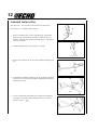
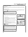
U-HANDLE INSTALLATION
Tools Required: 17 & 19 mm wrench, 4 mm hex socket wrench
Parts Required: U-Handle, Clamp w/screws
1. Remove assembling bolt (A) from right hand grip. Install right
hand grip (B) onto right hand U-handle (C) until bolt hole in U-
handle is visible through bolt hole in bottom of grip. Grip should
not rotate on handle.
2. Install assembling bolt to secure grip onto U-handle.
3. Remove bolt retainer tube (D) from end of handle assembling bolt
(E).
4. Install handle assembling bracket (upper) (F) in handle assembling
bracket (lower) (G) and secure handle by tightening handle assem-
bling bolt (E) loosely.
5. Loosen 4 right handle assembling bolts (H) and insert right hand
U-handle (C) into right handle assembling bracket (I). (toward
direction of arrow ).
D
E
F
G
E
H
I
C

GRASS TRIMMER/BRUSH CUTTER
OPERATOR'S MANUAL
13
6. Secure the right hand U-handle by tightening 4 right handle assem-
bling bolts (H) loosely.
7. Adjust handles for comfortable operation and tighten handle as-
sembling bolt (E) and 4 right handle assembling bolts (H).
8. Route throttle linkage and ignition lead assembly along shaft and
clip as shown.
E
H
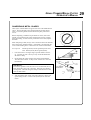
BALANCE AND ADJUST UNIT
1. Loosen harness clamp screw.
2. Put on harness and attach unit to harness.
3. Slide harness clamp up (A) or down until unit balances with head
approximately 50-75 mm (2 -3 in.) from the ground.
4. Tighten harness clamp screw.
5. Loosen upper U-Handle clamp screws (B), and position U-Handle
for comfortable operation.
6. Tighten U-Handle clamp screws and 8 mm clamp bolt securely.
A
B

14
OPTIONAL NYLON HEAD INSTALLATION
Tools Required: Locking Tool
Parts Required: Nylon Line Head.
1. Align hole in upper plate with notch in gear housing, and insert
locking tool to prevent splined shaft from turning.
2. Thread line head onto PTO shaft by turning it counter-clockwise
until head is tight against upper plate.
3. Remove locking tool.
• Read the Operator’s Manual carefully. Be thoroughly familiar
with the controls and proper use of the trimmer.
Know how to stop the unit and disengage the controls.
• Never allow children to operate the trimmer.
• Never allow adults to use the trimmer unless they have received
proper instructions. Be sure the operator is properly attired and
wears the type of foot, leg, head, eye and ear protection recom-
mended both in your ECHO Operator’s Manual and by your
ECHO Servicing Dealer.
• Always wear eye protection that conforms to ANSI Z 87.
1-2000.1. Read the Operator’s Manual carefully. Be thoroughly
familiar with the controls and proper use of the trimmer.
Know how to stop the unit and disengage the controls.
WARNING
Grass/weed trimmers can throw gravel, stone, wood chips, glass,
and plastic or metal objects. The debris shield behind the trimmer
head stops much of the debris, but cannot prevent the operator from
being struck by some debris. Read the rules for safe operation in
the operator’s manual that you received with your ECHO trimmer.
Also, follow all instructions in this instruction sheet.
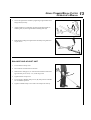
1. REPLACING LINE
A. Remove spool by turning knob clockwise, “right”, and separating
parts.
B. Thread a 6 m (20 feet) length of 2.4 mm (0.095 in) or 2.7 mm
(0.105 in) ECHO line through hole in spool so that ends are the
same length.
C. Wind both ends of line tightly and evenly clockwise (see arrows on
spool), and wind from side to side without twisting the lines.
D. Secure ends of line temporarily with about 15 cm (6 in) extending
out.
spool
15 cm

GRASS TRIMMER/BRUSH CUTTER
OPERATOR'S MANUAL
15
2.REPLACING SPOOL
NOTE
Keep line tight on spool.
A. Snap spool into housing while pulling line through eyelets with
about 15 cm (6 in) extending out.
CAUTION
Knob tightens counterclockwise, “left”.
B. Fasten spool to housing with shaft bolt, spring, and knob.
OPERATING INSTRUCTIONS NYLON LINE
1. Always use the end of the line for cutting. Forcing the cutter head
too close to the work will result in reduced effi ciency and broken
line.
2. Maintain the line at the recommended length of 12.5 to 15 cm (5
to 6 in). A longer line will reduce engine speed, a shorter line may
result in engine damage.
3. The trimmer head rotates counterclockwise. Always cut with the
head tilted to the right to defl ect debris away from the operator.
4. Always observe the SAFETY RULES on Page 3 when using the
unit.
Housing
Bolt
Spring
Knob

16
OPERATION
WARNING
Moving parts can amputate fi ngers or cause severe injuries. Keep hands, clothing and loose objects away from all
openings. Always stop engine, disconnect spark plug, and make sure all moving parts have come to a complete
stop before removing obstructions, clearing debris, or servicing unit.
WARNING
Engine exhaust IS HOT, and contains Carbon Monoxide (CO), a poison gas. Breathing CO can cause unconscious-
ness, serious injury, or death. Exhaust can cause serious burns. ALWAYS position unit so that exhaust is directed
away from your face and body.
WARNING
Operation of this equipment may create sparks that can start res. is unit is equipped with a spark arrestor to
prevent discharge of hot particles from the engine. Metal blade use also can create sparks if the blade strikes rocks,
metal, or other hard objects. Contact local re authorities for laws or regulations regarding re prevention require-
ments.
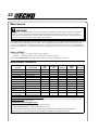
BLADE SELECTION
WARNING
The type of Blade used MUST be matched to the type and size of material cut. An improper or dull blade can cause
serious personal injury. Blades MUST be sharp. Dull blades increase the chance of kick-out and injury to yourself
and bystanders.
NOTE
e Barrier Bar is used to restrict rearward movement of the unit. e Barrier Bar is NOT A HANDLE and should
not be gripped when using or carrying the unit.
TO USE
THESE BLADES
Pro Maxi-Cut
Grass/Weed
Blade
Rigid Plastic
Tri-Cut
Grass/Weed Blade
Metal Blade
You
must
install
these
parts!
Loop Handle, w/or
w/o Barrier Bar
U-Handle or Loop Handle
w/Barrier Bar
U-Handle or Loop
Handle
w/Barrier Bar
Plastic Shield Plastic Shield Metal Shield
Harness Harness Harness
Upper Plate &
Flat Washer
Upper Plate
& Glide Cup
Upper/Lower
Blade Plates
Hex Nut Hex Nut Hex Nut
New Cotter Pin New Cotter Pin New Cotter Pin
• WARNING! DO NOT INSTALL BLADES ON GT (CURVED SHAFT) MODEL TRIMMERS
• Arbor diameter of Upper Blade Plate must match arbor diameter of blades.
• New cotter pin required each time blade is installed.
• Brush Cutters over 16.5 lbs (7.5 kg) dry weight (weight w/o fuel) require a double shoulder harness
BLADE SET-UP GUIDE

GRASS TRIMMER/BRUSH CUTTER
OPERATOR'S MANUAL
17
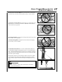
Plastic/Nylon Grass/Weed Blades may be used where ever the nylon
line head is used. DO NOT use this blade for heavy weeds or brush!
8 Tooth Grass and Weed Blade is designed for grass, garden debris and
thick weeds up to 19 mm (3/4”) diameter. DO NOT use this blade for
brush or heavy woody growth.
80 Tooth Brush Blade is designed for cutting brush and woody growth
up to 13 mm (1/2 in.) diameter.
22 Tooth Clearing Blade is designed for dense thickets and saplings
up to 64 mm (2 1/2 in.) diameter.
WARNING
In case of emergency, pull the quick release latch to disconnect
the trimmer from the harness.
Use Shoulder/Waist Harness Use of the Shoulder/Waist Harness is
recommended for ALL Trimmer/Brush Cutter use, not just Blade oper-
ation. The Shoulder/Waist Harness when used in a trimming operation
with nylon line head suspends the trimmer from the operator's shoulder
and reduces operator fatigue.
During blade operation, the same fatigue reduction is achieved. Safety
to the operator is also enhanced by reducing the possibility of blade
contact with the operator's hands and feet by restricting trimmer move-
ment

18
FUEL
NOTICE: Use of unmixed, improperly mixed, or fuel older than 90 days, (stale fuel), may cause hard starting, poor
performance, or severe engine damage and void the product warranty. Read and follow instructions in the Storage
section of this manual.
WARNING
Alternative fuels, such as E-15 (15 % ethanol), E-85 (85 % ethanol) or any fuels not meeting ECHO requirements
are NOT approved for use in ECHO 2-stroke gasoline engines. Use of alternative fuels may cause performance
problems, loss of power, overheating, fuel vapor lock, and unintended machine operation, including, but not limited
to, improper clutch engagement. Alternative fuels may also cause premature deterioration of fuel lines, gaskets,
carburetors and other engine components.
Fuel Requirements
Gasoline - Use 89 Octane [R+M/2] (mid grade or higher) gasoline known to be good quality. Gasoline may contain
up to 10 % Ethanol (grain alcohol) or 15 % MTBE (methyl tertiary-butyl ether). Gasoline containing methanol (wood
alcohol) is NOT approved.
Two Stroke Oil - A two-stroke engine oil meeting ISO-L-EGD (ISO/CD 13738) and J.A.S.O. FC/FD Standards must
be used. ECHO brand premium Power Blend X
TM
Universal 2-Stroke Oil meets these standards. Engine problems due to
inadequate lubrication caused by failure to use an ISO-L-EGD (ISO/CD 13738) and J.A.S.O. FC/FD certifi ed oil, such
as ECHO premium Power Blend X
TM
, will void the two-stroke engine warranty.
IMPORTANT
ECHO premium Power Blend X
TM
Universal 2-Stroke Oil may be mixed at 50:1 ratio for application in all ECHO
engines sold in the past regardless of ratio specifi ed in those manuals.
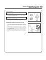
Handling Fuel
DANGER
Fuel is VERY fl ammable. Use extreme care when mixing, storing or handling or serious personal injury may result.
• Use an approved fuel container.
• DO NOT smoke near fuel.
• DO NOT allow fl ames or sparks near fuel.
• Fuel tanks/cans may be under pressure. Always loosen fuel caps slowly allowing pressure to equalize.
• NEVER refuel a unit when the engine is HOT or RUNNING!
• DO NOT fi ll fuel tanks indoors. ALWAYS fi ll fuel tanks outdoors over bare ground.
• DO NOT overfi ll fuel tank. Wipe up spills immediately.
• Securely tighten fuel tank cap and close fuel container after refueling.
• Inspect for fuel leakage. If fuel leakage is found, do not start or operate unit until leakage is repaired.
• Move at least 3m (10 ft.) from refueling location before starting the engine.

GRASS TRIMMER/BRUSH CUTTER
OPERATOR'S MANUAL
19
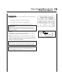
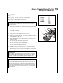
Mixing Instructions
1. Fill an approved fuel container with half of the required amount of
gasoline.
2. Add the proper amount of 2-stroke oil to gasoline.
3. Close container and shake to mix oil with gasoline.
4. Add remaining gasoline, close fuel container, and remix.
IMPORTANT
Spilled fuel is a leading cause of hydrocarbon emissions. Some
states may require the use of automatic fuel shut-off containers to
reduce fuel spillage.
After use
• DO NOT store a unit with fuel in its tank. Leaks can occur. Return
unused fuel to an approved fuel storage container.
Storage - Fuel storage laws vary by locality. Contact your local gov-
ernment for the laws affecting your area. As a precaution, store fuel in
an approved, airtight container. Store in a well-ventilated, unoccupied
building, away from sparks and fl ames.
IMPORTANT
Stored fuel ages. Do not mix more fuel than you expect to use in
thirty (30) days, ninety (90) days when a fuel stabilizer is added.
IMPORTANT
Stored two-stroke fuel may separate. ALWAYS shake fuel con-
tainer thoroughly before each use.
Shoulder
level
Fuel tank

20
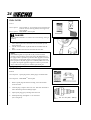
STARTING COLD ENGINE
WARNING
When engine is started, confi rm that there is not any abnormal
vibration or sound. If there is abnormal vibration or sound, ask
your DEALER to repair. After refueling tighten fuel cap fi rmly and
check for leakage. In case of fuel leakage repair before starting
operation since there is a danger of fi re.
WARNING
e attachment will operate immediately when the engine starts,
and could result in possible serious injury. Keep movable parts of
the attachment away from objects that could become entangled or
thrown, and surfaces that could cause loss of control.
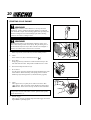
1. Stop Switch
Move stop switch (A) forward away from the STOP position.
2. Choke
Move choke lever (B) to Cold Start Position (
).
3. Purge Bulb
Pump purge bulb (C) until fuel is visible and fl ows freely in the
clear fuel tank return line. Pump bulb an additional 4 or 5 times.
4. Press the decompression device (E).
5. Recoil Starter
Lay the unit on a fl at area and keep movable attachment parts clear
of all obstacles. Hold unit fi rmly, and rapidly pull recoil starter
handle/rope (D) until engine fi res (or maximum fi ve [5] pulls).
6. Choke
After engine fi res (or 5 pulls), move choke lever back to Run
(
) position. Pull recoil starter starter handle/rope until engine
starts and runs. Allow unit to warm up at idle for several minutes.
NOTE
If engine does not start with choke in “Run” position after 5 pulls,
repeat instructions 2 - 5.
7. Throttle Trigger
After engine warm-up, gradually depress throttle trigger to increase
engine RPM to operating speed.
A
B
C
D
E
D
Page is loading ...
Page is loading ...
Page is loading ...
Page is loading ...
Page is loading ...
Page is loading ...
Page is loading ...
Page is loading ...
Page is loading ...
Page is loading ...
Page is loading ...
Page is loading ...
Page is loading ...
Page is loading ...
Page is loading ...
Page is loading ...
-
 1
1
-
 2
2
-
 3
3
-
 4
4
-
 5
5
-
 6
6
-
 7
7
-
 8
8
-
 9
9
-
 10
10
-
 11
11
-
 12
12
-
 13
13
-
 14
14
-
 15
15
-
 16
16
-
 17
17
-
 18
18
-
 19
19
-
 20
20
-
 21
21
-
 22
22
-
 23
23
-
 24
24
-
 25
25
-
 26
26
-
 27
27
-
 28
28
-
 29
29
-
 30
30
-
 31
31
-
 32
32
-
 33
33
-
 34
34
-
 35
35
-
 36
36


Ask a question and I''ll find the answer in the document
Finding information in a document is now easier with AI
Related papers
Other documents
-
Shindaiwa C303TS User manual
-
-
-
-
-
-
-
-
-