
V 1 . 0 ( 0 9 / 2 0 2 2 )
METT 4 IN 1 EXHAUST FAN
SKU# 209047
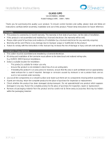
CAUTION
READ INSTRUCTIONS CAREFULLY FOR SAFE
INSTALLATION AND FAN OPERATION.

METT 4 in 1 Exhaust Fan Installation Instructions
1 | P a g e v 1 . 0 ( 10/ 2 0 2 2 )
WARRANTY
- This product is covered by a 3-year warranty. The warranty is from the date of purchase, not the date of
installation.
- If this product is not installed by a licensed electrician, the warranty will be void.
- All wiring and installation of this product must adhere to the latest local and national wiring rules.
e.g. AS/NZS 3000 Electrical Installations.
- Please retain proof of purchase and evidence of installation by a licensed electrician for any warranty
enquiries.
- Warranty will be void if there is any damage due to improper usage or modification to the product.
- Failure to comply with the instructions in this manual may cause damage or injury and will void warranty.
- Please do not attempt to open or repair the heater yourself. Doing so could void the warranty and cause
damage or personal injury.
GENERAL SAFETY WARNING
1. Use this heater in accordance to the instructions outlined in this manual.
2. Ensure power to the circuit you are working on has been switched OFF before commencing any electrical
work.
3. The heater must be properly grounded/earth.
4. Do not touch the heater grille outlet or fascia when in use.
5. Wait for the heater to cool down before cleaning or maintenance.
6. Never use the heater without the panel or fascia.
7. This appliance is not intended for use by persons, including children, with reduced physical, mental or
sensory capabilities, or lack of knowledge and understanding, unless they are supervised and or given
instruction concerning the use of the appliance by someone responsible for their safety.
8. This appliance is not a toy. Children should be supervised to ensure that they do not play with the appliance.
INSTALLATION WARNINGS
1. This heater must not be located / installed immediately below a socket outlet.
2. Installation of the wall switch for this appliance must adhere to all current building regulations.i.e.,When
Used in a bathroom, the switch should not be able to be reached or operated by a person within the bath
Or shower.
3. This heater shall, under no circumstances, be covered with insulating material or similar material.
4. Regulations concerning the discharge of air have to be fulfilled.
5. Joists, beams and rafters shall not be cut or notched to install this heater.
6. Installation is to be no less than 2.0 metres from the floor.
7. The product must be installed in a flat ceiling. Do not install on a sloped ceiling, or vertically.
8. Take care not to pull any electrical wires during unpacking as this may damage the connection.
9. Lay out all the components on a smooth surface and make sure there are no components missing before
assembling. If parts are missing, return the complete product to the place of purchase for inspection or
replacement.
10. Check whether the fitting has been damaged during transport. Do not operate/install any product which
appears damaged in any way. Return the complete product to the place of purchase for inspection, repair
or replacement.

METT 4 in 1 Exhaust Fan Installation Instructions
2 | P a g e v 1 . 0 ( 10/ 2 0 2 2 )
PERFORMANCE NOTES
1. For exhaust fan optimum performance, volume of air being extracted should be equal to the amount of
air entering the room. Air is drawn mostly from under a door, or an open window. If the bathroom or room
is air tight (door and windows shut), the exhaust will not perform well.
2. The heater will work most effectively if you are standing directly under the appliance.
3. LED lighting of the appliance is designed to provide directional lighting only. While it may be sufficient for
most common tasks, others such as shaving or applying make-up may require additional lighting.
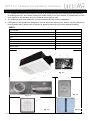
PARTS
PTC Heater
A
LED lighting fixture
B
Air Duct (150mm)
C
Fan
D
Exhaust Fan
E
Aluminium Duct
F
Wall switch
G
Outlet Grille
H
Cut-out Template
I
Fig. 1.1
Fig. 1.2
Fig. 1.3
Fig. 1.4
Fig. 1.5

METT 4 in 1 Exhaust Fan Installation Instructions
3 | P a g e v 1 . 0 ( 10/ 2 0 2 2 )
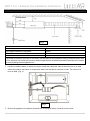
INSTALLATION INSTRUCTIONS
Clearance requirement
HCB-Height clearance to building element
20mm
HCI-Height clearance to insulation
10mm
SCB-Side clearance to building element
15mm
SCI-Side clearance to insulation
20mm
The distance between the sides of the heater and the sides and any adjacent ceiling recessed heater shall
not be less than four times the minimum distance specified for the distance between the sides of the heater
and any building element adjacent to it.
1. Locate a suitable location in which you wish to install the heater fan. Note it should not be in an area
where the product may come in contact with water such as above a shower or bath. The centre of a
room is ideal. (Fig. 3)
2. Ensure the appliance is installed, recessed into a ceiling at least 2.0 metres from the floor.
Fig. 3
Fig. 2

METT 4 in 1 Exhaust Fan Installation Instructions
4 | P a g e v 1 . 0 ( 10/ 2 0 2 2 )
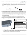
3. Use the cut-out template card as a template. Place in the required location and mark out the hole cutting
size:523mm x 343mm. Before commencing cutting ensure that the area behind the intended location is
clear of all cables, pipes and joists. Once clear, cut out the section along the previously marked lines.
(Fig. 4)
4. Determine the length of Aluminium Duct required between METT fan outlet and the out grille (Fig. 9) as
show in the diagram above (Fig. 2 & 3). 3 meters of Aluminium duct are provided. Cut Aluminium duct to
appropriate length and connect the METT fan and out grille. fit Aluminium duct to the outlet of the METT
fan and feed to outlet of the wall grille. Use tape to secure this Aluminium duct connection if required.
We recommend the location of the grille (Fig.9) on the exterior wall/surface of the building in such that
the ducting is routed as straight and linear as possible between the METT fan and the grille outlet. This
will ensure best air extraction.
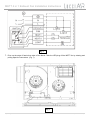
5. Remove the terminal cover on the side of the METT fan, Connect the supply wires to the terminal block
on the side of the METT fan. Complete in accordance with the wiring diagram shown in Fig. 6
6. Make the wiring connection of the wall switch supplied to the terminal block on the METT fan, using
wiring diagram shown in Fig. 6, make sure all cables are securely connected and refit the terminal box
cover.
• The electric mains should be equipped with an automatic circuit breaker with a rated current
not less than 10A.
• The heater must not be located immediately below a power point. Power point should not be
located at the back of the heater. The power point needs to be located outside the physical
footprint of the heater to minimise heat build-up behind the heater.
Caution: For your safety - All electrical wiring
connections must be performed by a licensed
electrician.
Fig. 5
WARNING: FOR SAFE USE OF THIS
APPLIANCE, MEANS FOR ALL-POLE
DISCONNECTION MUST BE INCORPORATED
IN THE FIXED WIRING IN ACCORDANCE WITH
THE WIRING RULES..
This is a requirement of clause 7.12.2 of the
household appliance Standard AS/NZS 60335.1
(The latest standard edition) Please note warranty
will be void if installed without a means for an all-
pole disconnection included in the wiring.
Fig. 4

METT 4 in 1 Exhaust Fan Installation Instructions
5 | P a g e v 1 . 0 ( 10/ 2 0 2 2 )
7. Prise up the edge of fascia then take off the fascia. Take the LED plug off the METT fan by twisting and
pulling apart the connectors. (Fig. 7)
Fig. 7
Fig. 6

METT 4 in 1 Exhaust Fan Installation Instructions
6 | P a g e v 1 . 0 ( 10/ 2 0 2 2 )
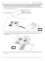
8. Insert the METT fan (without the fascia) into the installation hole (step 3) and push up. Ensure the 6
metal clips are push into the body and do stick out, when inserting the METT fan into the installation
hole. Use a screw driver to tighten the screws until the mounting clips swing outside the body and clamp
down onto the ceiling tightly. (Fig. 8)
9. Connect the LED plug to the fascia then attach fascia to the METT fan body, making sure all fixing clips
have located correctly. Ensure the LED power connector and wires are not near the heater while
replacing fascia.
10. Switch ON to check the function and operation as per described in the “USE AND OPERATION” section
are correct.
Fig. 8
Fig. 9

METT 4 in 1 Exhaust Fan Installation Instructions
7 | P a g e v 1 . 0 ( 10/ 2 0 2 2 )
INSTALLING THE GRILLE
1. Cut a 150mm round hole in your wall or eave.
2. Feed the ducting tube through the hole and connect to grille. Ensure connection is secure.
3. Feed the ducting tube back through the wall and into the cavity until the grille is secure and sits flush
against the wall or eave.
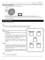
USE AND OPERATION
Your METT Fan with LED Light is controlled by a 5 gang wall control. Each switch turns on and off each
function individually as follows:
Fan
Please note: “Fan” must be switched on before Heat function can operate.
• Use “Fan” only (without “Heat”) for cooling effect in warmer weather.
Heat
Please note: “Heat Functions” will only operate after ‘Fan’ has
been switched on.
• Stand directly underneath the fan heater for maximum
heating effect.
• In cooler weather, turn the heater on 5 to 10 minutes
before having a bath or shower. This will warm the
environment, helping to minimise steam production and
condensation on the mirrors and walls.
• In high steam conditions, use the exhaust function in
tandem with the heat function to maximise steam
removal.
Exhaust
• For maximum exhaust performance, there must be
sufficient replacement intake air available through either
an ajar door, an adequate size gap underneath the door
or an air vent in the door.
• In high steam conditions, run exhaust for several minutes
after leaving the bathroom to help with condensation and
moisture control.
Light
• LED Light 20W 1400LM 4000K
Fig. 10

METT 4 in 1 Exhaust Fan Installation Instructions
8 | P a g e v 1 . 0 ( 10/ 2 0 2 2 )
CARE & MAINTENANCE
NOTE: Always turn OFF the power at the mains switch before performing any maintenance or
attempting to clean your fan.
1. Turn off power before cleaning.
2. Ensure the appliance has cooled before touching.
3. The LED light source cannot be replaced.
4. Clean the fascia and airways regularly. To clean, wipe with a soft damp clean cloth. DO NO use
organic/corrosive chemical/solvents or abrasive cleaners etc.
5. Do not soak or immerse your fan in the water or other liquids. It could damage the product and
create the possibility of an electrical shock.
SPECIFICATIONS
SKU #
209047
Colour
Matte White
Insulation class
Class I
IP rating
IPX2
Rated Voltage
220-240V~ 50Hz
Total Rated Wattage
2115W
(LED Light:20W / Exhaust:55W / Heater Unit & Fan: 2040W)
Light Specs
LED 20W 1400LM 4000K
Max. Airflow
380M3/H
Cut-out size
523mm x 343mm
Overall dimensions
L600mm(Including Duct Vent)*W375mm*H230mm Max.
Size of faceplate
L540mm*W375mm*H44mm
Exhaust outlet / Duct
size
Φ 150mm
Weight
8.3kg

METT 4 in 1 Exhaust Fan Installation Instructions
9 | P a g e v 1 . 0 ( 10/ 2 0 2 2 )
BATHROOM HEATER WARRANTY CARD
Our goods come with guarantees that cannot be excluded under the Australian Consumer Law. You are entitled
to a replacement or refund for a major failure and compensation for any other reasonably foreseeable loss or
damage. You are also entitled to have the goods repaired or replaced if the goods fail to be of acceptable quality
and the failure does not amount to a major failure.
Every Lucci Air Mett 4 in 1 is thoroughly inspected and tested before being released for sale. In addition to any warranties
or conditions implied by applicable Statue or Regulation, Lucci Design warrants all of it’s bathroom heaters against
defective workmanship and faulty materials for thirty six (36) months from the original date of purchase. Lucci Design
undertakes, at it’s option, to repair or replace, free of charge, each product or part thereof subject to the below warranty
conditions;
1) The fan or relevant part has not been modified, subjected to misuse, neglect, or been involved in an accident.
2) The repairs are not required as a result of normal wear and tear.
3) The product was installed by a licenced electrical contractor in accordance with this instruction manual.
4) No solid state speed control device has been used with the appliance.
5) A copy of the original receipt of purchase is presented.
6) Globes supplied are not covered by this warranty
Lucci Design cannot be held responsible for any repair other than those carried out by it or one of it’s Authorised
Service Agents. Please keep this warranty form in a safe place. This form must be produced in the event of
service being required.
IN THE EVENT OF SERVICE BEING REQUIRED, PLEASE CALL THE LUCCI FAN WARRANTY
HOTLINE ON 1800 602 243 BETWEEN 9AM & 5PM (E.S.T) MONDAY TO FRIDAY ENSURING
THAT YOU HAVE THE FOLLOWING DETAILS ON HAND:
MODEL (SKU) NUMBER: __________________________________________________________
DATE OF PURCHASE: ____________________________________________________________
RETAILER: _____________________________________________________________________
RECEIPT NUMBER: ______________________________________________________________
INSTALLED BY: _________________________________________________________________
LICENCE #:______________________________ PH: __________________________________
DESCRIPTION OF FAULT: _________________________________________________________
_________________________________________________________________
-
 1
1
-
 2
2
-
 3
3
-
 4
4
-
 5
5
-
 6
6
-
 7
7
-
 8
8
-
 9
9
-
 10
10


Beacon Lighting 209047 Mett 4 In 1 Exhaust Fan User manual
- Type
- User manual
- This manual is also suitable for
Ask a question and I''ll find the answer in the document
Finding information in a document is now easier with AI
Other documents
-
ResMed AirFit N20 Nasal Mask User guide
-
Lucci Air 209039 Installation guide
-
-
 Lucci CONNECT 299082 Installation guide
-
Lucci decor 200269 User manual
-
ML Accessories EX006T User manual
-
-
 Lucci CONNECT 216180 Installation guide
-
Manrose FAN7291 User manual
-
V I V O FAN7291 User manual

