Page is loading ...

NOTE: DIAGRAMS & ILLUSTRATIONS ARE NOT TO SCALE
1
SECURE FLEX® 36”
FLEX CONNECTOR KIT
HEARTH PRODUCTS
KITS AND ACCESSORIES
INSTALLATION INSTRUCTIONS FOR SECURE FLEX® CONNECTOR KIT (MODEL NO. FVK36)
(CATALOG NO. H7748) USED WITH DIRECT-VENT GAS FIREPLACE APPLICATIONS ONLY
GENERAL APPLICATIONS
This kit is designed to accommodate attaching two separate sections of
Rigid Secure Vent® runs. The slip pipe component is to be installed over
the leading end of the second rigid run to change its orientation from the
leading (female) connection to that of the male (normally trailing) end.
Once re-oriented, this end will now match the trailing end of the first rigid
run and both ends can be mated with the flex adaptors of this kit.
Connect the fixed (attached) adaptor to the slip pipe and the loose adaptor
to the trailing end of the first run. Pull the flex lengths to the second adap-
tor (inner first, outer last) and secure it to the adaptor with the provided
gear clamps. For detailed instructions, refer to the following information.
P/N 506022-04
Rev. A 05/2014
KIT CONTENTS
2 ea. 36” Flex Component
1 ea. Gear Clamp 7”
1 ea. Gear Clamp 4”
1 ea. SV4.5LA 2” to 7-1/2” Adjustable Length Slip Section
6 ea. Spring Spacers (inside the flex component)
1 ea. Instruction Sheet
GENERAL INFORMATION
This Secure Flex® venting kit may be used when venting an IHP direct-vent
gas fireplace. It contains 3’ of compressed flex vent, fitted to an adaptor,
a second adaptor, two gear clamps and a single SV4.5LA slip pipe.
If you encounter any problems, need clarification of these instructions or
are not qualified to properly install this kit, contact you local distributor
or dealer.
Read this instruction sheet in its entirety before beginning the installation.
ALL WARNINGS AND PRECAUTIONS IN THE INSTALLATION AND
OPERATION MANUAL PROVIDED WITH THE APPLIANCE APPLY TO
THESE INSTRUCTIONS.
Refer to the fireplace installation instructions for approved venting con-
figurations. Rigid Secure Vent (SV4.5) direct-vent components are shown
in these configurations; however, Secure Flex vent kits may also be used.
All the restrictions such as venting length, height, routing, horizontal to
vertical ratio requirements or clearance considerations as detailed in the
fireplace installation instructions for rigid vent must be adhered to for
the flexible vent.
Expanding Secure Flex and Secure Flex Joining Restrictions -
Flexible vent pipe is packaged and shipped in its contracted state. When
installing flexible vent pipe, its length may be expanded up to twice its
contracted size. This 3’ section of flexible pipe may be expanded up to
6’. The 3’ section may be cut to any length to suit a particular application;
however, the flex sections must not be joined together to extend a
vent run. After expanding the vent, check that the vent’s spring spacers
are spaced every 12” or less.
Inserting Secure Flex into a run of a Secure Vent (Rigid Vent) -
This Secure Flex component may be inserted into a vent run made up of
rigid Secure Vent (SV4.5) vent sections. The flex adaptor (87L00) and
the slip pipe (SV4.5LA) must be used when connecting this flexible pipe
component to the rigid.
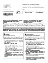
Installation of SV4.5LA Slip Pipe Section -
Locate the leading end of the second rigid run as identified by the four
evenly spaced dimples ringing the vent pipe outer component, shown in
Figure 1. Ensure that SV4.5LA can freely slip over the pipe by at least
6”, if not install at least a 6” length of rigid Secure Vent pipe. Drill three
pilot holes through the SV4.5LA and the outer vent 120 degrees apart and
secure SV4.5LA to the vent pipe with three screws.
Connecting the Flex Component to the SV4.5LA (refer to Figure 1) -
Align the dimpled end of the flex component adaptor over the previously
installed SV4.5LA collar, adjusting the radial alignment until the four lock-
ing dimples of the adaptor are aligned with the inlets of the four incline
channels of the SV4.5LA. Push on the adaptor until it fully engages, then
twist the adaptor clockwise running the dimples down and along the incline
channels until they seat at the end of the channels. Refer to Figure 1.
Figure 1
INSTALLATION INSTRUCTIONS
Locking
Dimple
Flex
Component
Flex Component Adaptor
Evenly Spaced
Screws
Inclined
Channel
Second Rigid
Vent Run
Installed
SV4.5LA Slip
Pipe Section
FIREPLACE
4/15/2014
IMPORTANT: INSTALLATION SHOULD BE PERFORMED BY A
QUALIFIED TECHNICIAN ACCORDING TO THESE INSTRUC-
TIONS, THE INSTALLATION INSTRUCTIONS FOR THE PAR-
TICULAR APPLIANCE BEING INSTALLED, AND LOCAL CODES.

2
Routing Secure Flex® Vent -
Ensure that the flex vent is properly routed to provide the required clear-
ance. Do Not allow the flexible vent to bend in a radius tighter than 5”
(127 mm). Refer to Figure 4. Space out the internal flex vent spacers
evenly and avoid kinking of inner pipe. We recommend venting should
be sloped upward toward the termination a minimum of 1/4” rise per foot
(20mm per meter) of horizontal vent run. Support the horizontal vent
sections using metal straps spaced at 2’ (0.61 meter) intervals.
Printed in U.S.A. © 2009 IHP LLC
P/N 506022-04 Rev. A 05/2014
Figure 3 - Connecting Flex To Flex Adaptor
1-3/4” (44 mm)
Flexible Pipe and
Adaptor Outer
Collar Overlap
Gear
Clamps
Adaptor
(SV4.5RF)
Apply ONLY MIL-PAC BLACK
HIGH TEMPERATURE SEALANT
(Catalog No. 10K81) to the
outside surface of both collars
of the adaptor (be especially
careful to fill the grooves of the
outer collar to be covered by
the flexible pipe) and slide
flexible pipe over inner and
outer adaptor collars.
NOTE: OUTER PIPE IS PULLED AWAY TO SHOW THE DETAIL OF THE INNER PIPE
Flex Vent
1-3/4” (44 mm)
Flexible Pipe and
Adaptor Inner
Collar Overlap
Attach Adaptor to Appliance
Collar, or Secure Vent Sections
Securing Screw
(3 Places equally
Spaced Just Below
Gear Clamp)
Securing Screw
(3 Places equally
Spaced Just Below
Gear Clamp)
Figure 4 - Minimum Flex Bend Radius
5" (127 mm)
Radius Minimum
Flexible
Vent Section
Attaching the Flexible Vent to the Adaptor (See parts A and B below
and refer to Figure 3 ) -
A. Install the Inner Flex Pipe -
1. Install the small gear clamp loosely around the inner flexible vent pipe,
push it back out of the way.
2. Apply a bead of Mill-Pac Black (700°F) high temperature sealant -
Catalog No. 10K81) to the inner adaptor collar, approximately 1/2”
from the end.
3. Pull and extend the inner flexible vent pipe.
4. Slide the inner flex pipe over the adaptor collar. Overlap the flexible vent
pipe with the adaptor collar 1-3/4”, ensuring that flexible vent pipe is
free from damage or tears.
5. Slide the gear clamp down to approximately 3/4” from the end of the
flexible pipe. Tighten the clamp fully to secure the flexible pipe to the
inner adaptor collar.
6. Install three screws 120 degrees apart through the flexible vent pipe
and into the adaptor collar just below the gear clamp to provide ad-
ditional security to the connection.
B. Install the Outer Flex Pipe -
1. Install the large gear clamp loosely around the outer flexible vent pipe,
push it back out of the way.
2. Apply a bead of Mill-Pac Black (700°F) high temperature sealant
- Catalog No. 10K81) to the outer adaptor collar; to the grooves of
the collar which extend approximately 1” from the end and to the flat
surface, approximately 1-3/8” from the end.
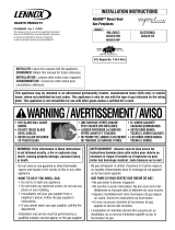
Figure 2
Installation of Secure Flex® Adaptor (87L00) -
The Secure Flex® kit comes with an adaptor (catalog no. 87L00) that can
be fitted to the appliance collar or the inclined channel end (male) of the
last (trailing) Secure Vent® section (SV4.5) in a rigid system. Align the
dimpled end of the adaptor over the previously installed section or appli-
ance collar, adjusting the radial alignment until the four locking dimples
of the adaptor are aligned with the inlets of the four incline channels of
the last vent section or collar. Push on the adaptor until it fully engages,
then twist the adaptor clockwise running the dimples down and along the
incline channels until they seat at the end of the channels. See Figure 2.
Flex
Adaptor
Align the dimple (four places)
with the opening of the locking
incline channel on appliance
collar. Twist vent component
clockwise to engage and seal.
Locking
Incline Channel
3. Pull and extend the outer flexible vent pipe.
4. Slide the outer flex pipe over the adaptor collar. Overlap the flexible
vent pipe with the adaptor collar 1-3/4”, ensuring that the flexible vent
pipe is free from damage or tears.
5. Slide the gear clamp down to approximately 3/4” from the end of the
flexible pipe. Tighten the clamp fully to secure the flexible pipe to the
outer adaptor collar.
6. Install three screws 120 degrees apart through the flexible vent pipe
and into the adaptor collar just below the gear clamp to provide ad-
ditional security to the connection.
CONNECTING FLEX ADAPTOR TO APPLIANCE COLLAR
OR LAST VENT COMPONENT
IHP reserves the right to make changes at any time, without notice, in design, materials,
specifications, prices and also to discontinue colors, styles and products. Consult your local
distributor for fireplace code information.
1508 Elm Hill Pike, Suite 108 • Nashville, TN 37210
NOTE: DIAGRAMS AND ILLUSTRATIONS ARE NOT TO SCALE.
/