
myTEM Radio RGBW module
MTRGB-100-WL
The myTEM Radio RGBW MTRGB-100-WL is a
module for controlling and dimming 4-coloured LED
strips. In addition to the red-green-blue-white color
control, a warm white setting can be realized if the
LED strip supports this function.
Further information can be found on our website:
https://www.mytem-smarthome.com/web/en/download
ATTENTION:
This device is not a toy. Please keep it away from
children and animals!
Please read the manual before attempting to in-
stall the device!
These instructions are part of the product and
must remain with the end user.
Warning and safety instructions
WARNING!
This word indicates a hazard with a risk that, if not
avoided, can result in death or serious injury. Work on
the device must only be carried out by persons with
the necessary training or instruction.
CAUTION!
This word warns of possible damage to property.
115’005 Version: 11/2019
SAFETY INSTRUCTIONS
Operate this device only as described in the manual.
Do not operate this device if it has obvious damage.
This device shall not be altered, modified or opened.
This device is intended for use in buildings in a dry,
dust-free location.
This device is intended for installation in a control
cabinet. After installation, it must not be openly acces-
sible.
DISCLAIMER
All rights reserved. This is a translation from the original
version in German.
This manual may not be reproduced in any format, either
in whole or in part, nor may it be duplicated or edited by
electronic, mechanical or chemical means, without the
written consent of the publisher.
The manufacturer, TEM AG, is not liable for any loss or
damage caused by failure to follow the instructions in the
manual.
Typographical and printing errors cannot be excluded.
However, the information contained in this manual is
reviewed on a regular basis and any necessary correc-
tions will be implemented in the next edition. We accept
no liability for technical or typographical errors or the
consequences thereof. Changes may be made without
prior notice as a result of technical advances. TEM AG
reserves the right to make changes to product design,
layout and driver revisions without notice to its users. This
version of the manual supersedes all previous versions.
Trademarks
myTEM and TEM are registered trademarks. All other
product names mentioned herein may be trademarks or
registered trademarks of their respective companies.
What is Z-Wave?
Z-Wave is the international wireless protocol for commu-
nication in the Smart Home. Z-Wave ensures a reliable
communication by reconfirming every message (two-way
communication) and every mains powered node can act
as a repeater for other nodes (meshed network) in case
the receiver is not in direct wireless range of the transmit-
ter.
Z-Wave products from different manufacturers can be
used together in a wireless network. Thus, this product
with any Z-Wave product from other manufacturers can
be used in a common Z-Wave wireless network.
The myTEM Radio RGBW module is a Z-Wave device
with secure communication (S2) and uses the radio
frequency of 868.4 MHz. If other devices also support the
same secure communication, the data is exchanged in
this secure mode. Otherwise it will switch automatically to
a lower level of security to maintain backward compatibil-
ity.
For more information about frequency regulations please
refer to the homepage of Silicon Labs. For more infor-
mation about Z-Wave technology, devices, tutorials, etc.
please refer to www.z-wave.info.
Product description
The myTEM Radio RGBW module MTRGB-100-WL is a
Z-Wave device of the type Light Dimmer Switch for use
in Europe / Switzerland. It can be used for controlling
and dimming 4-coloured LED strips. In addition to the red-
green-blue-white color control, a warm white setting can
also be realized if the LED strip supports this function.
The load is no longer switched directly via a (possibly
existing light) switch, but a signal is sent to a controller
like the myTEM Smart Server or the myTEM Radio Serv-
er, which in turn controls the myTEM Radio RGBW mod-
ule via radio.
The myTEM Radio RGBW module must be powered by a
24 VDC power supply and can control 24 VDC RGBW
LED strips or lamps. The device is installed in a control
cabinet, mounted on a 35 mm DIN rail.
Preparation for the installation
WARNING! Depending on national safety standards,
only authorized and/or trained technicians may be al-
lowed to make electrical installations on the power supply.
Please inform yourself about the legal situation before
installation.
In order to include (Add) a Z-Wave device to a network it
must be in factory default state. Please make sure to
reset the device into factory default. After power-up the
status is displayed as below:
Status Add (included in a Z-Wave network):
The LED lights green for 1-2 seconds
Status Remove (not included):
The LED flashes red for 5-10 seconds
Reset to factory default
If the myTEM Radio RGBW module shows the status
Add, the Remove can be performed with any controller in
the network or with the help of a new controller. However
it is recommended to use the primary controller of the
previous network unless it is no longer available or dam-
aged.
Remove deletes the memory chip, including all Z-Wave
network and custom configuration settings.
To start the Remove process, please press the button (T)
four times in quick succession. The LED flashes red and
then the new status is:
Add: The LED lights up briefly in green
Remove: The LED lights up briefly in red
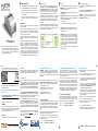
Installation
Please install the device according to the following steps:
1. WARNING! Make sure that the device is disconnect-
ed from the power supply.
2. CAUTION! Connect the myTEM Radio RGBW mod-
ule as shown above.
3. CAUTION! The device shall only be operated with
stabilized power supplies (24 VDC). Connecting higher
voltages will damage the device.
4. Turn on the power.
5. Include (Add) the module into the Z-Wave network.
CAUTION! The myTEM Radio RGBW module must
be operated with the same voltage supply as the con-
nected LED strips.
CAUTION! When connecting long LED strips, there
may be a loss of power. This can cause the luminosity
to decrease with lights farther away from the RGBW
outputs. To avoid this effect, several short, parallel
LED strips are recommended instead of a long, serial-
ly connected LED strip. It is also recommended to
connect LED strips with a maximum length of 10 m to
the RGBW outputs.
Please also note the instructions of the respective LED
strip manufacturer.
Inclusion/Exclusion (Add/Remove) of the device
On factory default the device does not belong to any
Z-Wave network. In order to communicate with other
Z-Wave devices, it must be included into an existing net-
work or a new network has to be established. In Z-Wave
this process is called “Add”.
Devices can also be removed from networks. In Z-Wave
this process is called “Remove”. Both processes are
initiated by the primary controller of the Z-Wave network.
This controller is put into the “Add”, respectively the “Re-
move” mode. The manual of the controller will contain the
information on how to switch it into these modes. Only
when the primary controller of the Z-Wave network is in
the “Add” mode can devices be added. Removing a de-
vice from the network will reset it to the delivery state.
Inclusion/Exclusion (Add/Remove)
To include/exclude (Add/Remove) the device to/from a
Z-Wave network, press the button T four times in quick
succession. When the device is in Add mode, the LED
flashes green. When finished, the new status is:
Add: The LED lights up briefly in green
Remove: The LED lights up briefly in red
Color and dimming settings
The command class Color Switch is used to set the
desired color.
The command class Multilevel Switch is used to set
the desired intensity (value for dimming).
CAUTION! By default, the values for the color and
intensity are 0, resp. set to OFF. To turn on the LED
strip BOTH values must be set.
Quick trouble shooting
The following hints may help solving trouble during
network installation.
1. Make sure that new devices are in factory reset
state. The status is displayed at power up.
2. If a connection cannot be established, check that
the controller and the device are working on the
same radio frequency.
3. If a connection cannot be established, the control
cabinet may reduce the radio signal. Please use
in this case an external antenna, such as, for
example, the myTEM MTANT-100-WL.
4. Remove devices that are no longer available in the
Z-Wave network from all association groups. Oth-
erwise significant delays in the execution of com-
mands are possible.
5. Make sure you have enough mains powered de-
vices to benefit from the meshing network.
6. Never use “sleeping” battery powered devices
without a central controller.
7. Do not poll battery powered devices.
8. Make sure you have set color and intensity values,
otherwise the LED strip will stay turned off.
© TEM AG; Triststrasse 8; CH – 7007 Chur

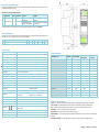
Z-Wave Association - Devices control each other
The Association Command Class is used to manage associations to NodeID destinations. An association group sends commands to the config-
ured destinations when triggered by an event.
Association group of the myTEM Radio RGBW module:
Group
ID
Profile / Name
Max. no
of units
Command Class
Type / Event
Description
1
General: NA / Lifeline
5
Notification Report
T: System (0x09)
E: Heartbeat (0x05)
Reports to be alive (interval according to
configuration)
T: Power Management (0x08)
E: Power has been applied (0x01)
Reports the device had a start-up (sent after
each power-up only)
The reports "Heartbeat" and "Power Management" can be activated / deactivated separately via the command class Notification.
Z-Wave configuration parameter
Z-Wave products can be used out of the box after inclusion (Add) into the network. However, configuration settings can adapt the behavior of the
device better to the needs of your application. This device uses the following parameter:
Par#
Description
Unit
Min
Max
Default
Precision
R/W
Size
1
Heartbeat rate
min
1
1440
60
0
r/w
2 bytes
Technical specifications
Dimensions (W × H × D)
37.3 × 101.1 × 62.5 mm (height with connectors 106.8 mm)
Installation / mounting
On 35 mm DIN rail
Operating voltage
24 VDC ± 10%
Power consumption in standby
Continuous operation for wireless network, therefore no standby operation
Power consumption in operation
0.3 W (MTRGB-100-WL only, without external LED strips)
RGBW outputs
Max. 50 W per LED channel
Ambient temperature for operation
0 °C – 50 °C
Ambient temperature for storage
-20 °C – 60 °C
Ambient humidity
5 %RH – 85 %RH (non condensing)
Wire cross-section connectors
0.25 mm² – 2.5 mm²
Stripping length for connectors
ca. 7 mm
Tightening torque for connectors
0.5 Nm
Degree of protection provided by enclosure
IP 20 (after installation) (according to EN 60529)
Protection class
III (according to EN 60730-1)
Overvoltage category
I (according to EN 60730-1, resp. EN 60664-1)
Pollution degree
2 (according to EN 60730-1)
Safety main unit
EN 60730-1:2016 EN 60730-2-9:2010
EMC main unit
EN 60730-1:2016 EN 60730-2-9:2010
EN 61000-6-2:2005 EN 61000-6-3:2007 + A1:2011/AC:2012
Safety radio part
EN 62368-1:2014/AC:2015 EN 62479:2010
EMC radio part
EN 301 489-1 V2.2.0 EN 301 489-3 V2.1.1
Radio spectrum
EN 300 220-2 V3.2.1
RoHS
EN 50581:2012
CE conformity
2014/30/EU (EMC) 2014/53/EU (RED)
2011/65/EU (RoHS)
Z-Wave hardware platform
ZM5101
Device Type
Light Dimmer Switch
Role Type
Always On Slave (AOS)
Supported Command Classes
Command Class (CC)
Not added
Non-secure added
Securely added,
Non-secure CC
Securely added,
Secure CC
Application Status CC
Support
Support
Support
Association CC
Support
Support
Support
Association Group Information CC
Support
Support
Support
Basic CC
Support
Support
Support
Color Switch CC
Support
Support
Support
Configuration CC
Support
Support
Support
Firmware Update Meta Data CC
Support
Support
Support
Manufacturer Specific CC
Support
Support
Support
Multilevel Switch CC
Support
Support
Support
Notification CC
Support
Support
Support
Powerlevel CC
Support
Support
Support
Security_2 CC
Support
Support
Support
Supervision CC
Support
Support
Support
Transport Service CC
Support
Support
Support
Version CC
Support
Support
Support
Z-Wave Plus Info CC
Support
Support
Support
Explanation of some Z-Wave specific terms
Controller... is a Z-Wave device with the capability to manage a network. They are typically gateways, remote controls or wall controllers.
Primary controller... is the central administrator of the Z-Wave network. In a Z-Wave network, only one primary controller is allowed.
Slave... is a Z-Wave device without the ability to manage a network. Slaves can be sensors, actuators and even remote controls.
Add (Inclusion)... is the process of adding new Z-Wave devices into a network.
Remove (Exclusion)... is the process of removing Z-Wave devices from the network.
Wakeup Notification... is a special wireless message issued by battery powered Z-Wave devices to announce that they are awake and able to
communicate.
Node Information Frame (NIF)... is a special wireless message issued by a Z-Wave device to announce its capabilities and functions.
© TEM AG; Triststrasse 8; CH – 7007 Chur
-
 1
1
-
 2
2


Ask a question and I''ll find the answer in the document
Finding information in a document is now easier with AI