
5D7-F8199-E0
YZF-R125
OWNER’S MANUAL

U5D7E0E0.book Page 2 Tuesday, December 18, 2007 10:13 AM

INTRODUCTION
EAU10100
Welcome to the Yamaha world of motorcycling!
As the owner of the YZF-R125, you are benefiting from Yamaha’s vast experience and newest technology regarding the de-
sign and manufacture of high-quality products, which have earned Yamaha a reputation for dependability.
Please take the time to read this manual thoroughly, so as to enjoy all advantages of your YZF-R125. The owner’s manual
does not only instruct you in how to operate, inspect and maintain your motorcycle, but also in how to safeguard yourself and
others from trouble and injury.
In addition, the many tips given in this manual will help keep your motorcycle in the best possible condition. If you have any
further questions, do not hesitate to contact your Yamaha dealer.
The Yamaha team wishes you many safe and pleasant rides. So, remember to put safety first!
U5D7E0E0.book Page 1 Tuesday, December 18, 2007 10:13 AM

IMPORTANT MANUAL INFORMATION
EAU10151
Particularly important information is distinguished in this manual by the following notations:
NOTE:
●This manual should be considered a permanent part of this motorcycle and should remain with it even if the motorcycle
is subsequently sold.
●Yamaha continually seeks advancements in product design and quality. Therefore, while this manual contains the most
current product information available at the time of printing, there may be minor discrepancies between your motorcycle
and this manual. If you have any questions concerning this manual, please consult your Yamaha dealer.
WARNING
EWA10030
PLEASE READ THIS MANUAL CAREFULLY AND COMPLETELY BEFORE OPERATING THIS MOTORCYCLE.
*Product and specifications are subject to change without notice.
The Safety Alert Symbol means ATTENTION! BECOME ALERT! YOUR SAFETY IS
INVOLVED!
Failure to follow WARNING instructions could result in severe injury or death to the
motorcycle operator, a bystander, or a person inspecting or repairing the motor-
cycle.
A CAUTION indicates special precautions that must be taken to avoid damage to
the motorcycle.
A NOTE provides key information to make procedures easier or clearer.
WARNING
CAUTION:
NOTE:
U5D7E0E0.book Page 1 Tuesday, December 18, 2007 10:13 AM

IMPORTANT MANUAL INFORMATION
EAUM1010
YZF-R125
OWNER’S MANUAL
©2007 by MBK INDUSTRIE
1st edition, November 2007
All rights reserved
Any reprinting or unauthorized use
without the written permission of
MBK INDUSTRIE
is expressly prohibited.
Printed in France.
U5D7E0E0.book Page 2 Tuesday, December 18, 2007 10:13 AM

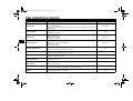
TABLE OF CONTENTS
SAFETY INFORMATION ..................1-1
DESCRIPTION ..................................2-1
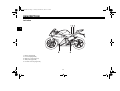
Left view ..........................................2-1
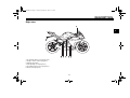
Right view........................................2-2
Controls and instruments.................2-3
INSTRUMENT AND CONTROL
FUNCTIONS .......................................3-1
Main switch/steering lock ................3-1
Indicator and warning lights ............3-2
Tachometer ....................................3-3
Multi-function display ......................3-3
Handlebar switches ........................3-4
Clutch lever .....................................3-5
Shift pedal .......................................3-6
Brake lever .....................................3-6
Brake pedal ....................................3-6
Fuel tank cap ..................................3-7
Fuel .................................................3-7
Catalytic converters ........................3-8
Rider seat .......................................3-9
Anti-theft device housing ................3-9
Sidestand ......................................3-10
Ignition circuit cut-off system ........3-10
PRE-OPERATION CHECKS..............4-1
Pre-operation check list ..................4-2
OPERATION AND IMPORTANT
RIDING POINTS................................. 5-1
Starting the engine ......................... 5-1
Shifting ........................................... 5-2
Tips for reducing fuel
consumption ...............................5-3
Engine break-in .............................. 5-3
Parking ........................................... 5-4
PERIODIC MAINTENANCE AND
MINOR REPAIR ................................. 6-1
Owner’s tool kit ............................... 6-1
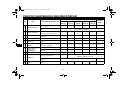
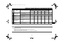
Periodic maintenance and
lubrication chart .......................... 6-2
Removing and installing the
cowlings and panel ..................... 6-6
Checking the spark plug ................. 6-8
Engine oil and oil filter element ...... 6-9
Coolant ......................................... 6-12
Replacing the air filter element
and cleaning the check hose .... 6-14
Adjusting the engine idling
speed ........................................ 6-14
Adjusting the throttle cable free
play ........................................... 6-15
Valve clearance ............................ 6-16
Tires ............................................. 6-16
Cast wheels .................................. 6-18
Adjusting the clutch lever free
play ........................................... 6-19
Checking the front brake lever
free play .................................... 6-20
Adjusting the brake pedal free
play ........................................... 6-20
Checking the front and rear
brake pads ................................ 6-20
Checking the brake fluid level ...... 6-21
Changing the brake fluid .............. 6-22
Drive chain slack .......................... 6-22
Cleaning and lubricating the
drive chain ................................ 6-24
Checking and lubricating the
cables ....................................... 6-24
Checking and lubricating the
throttle grip and cable ............... 6-25
Checking and lubricating the
brake and shift pedals .............. 6-25
Checking and lubricating the
brake and clutch levers ............ 6-26
Checking and lubricating the
sidestand .................................. 6-26
Lubricating the swingarm
pivots ........................................ 6-27
Checking the front fork ................. 6-27
Checking the steering .................. 6-28
Checking the wheel bearings ....... 6-28
Battery ......................................... 6-29
Replacing the fuses ..................... 6-30
Replacing a headlight bulb .......... 6-31
Tail/brake light ............................. 6-31
U5D7E0E0.book Page 1 Tuesday, December 18, 2007 10:13 AM

TABLE OF CONTENTS
Replacing a turn signal light
bulb ...........................................6-31
Replacing the license plate light
bulb ...........................................6-32
Replacing an auxiliary light bulb ...6-32
Supporting the motorcycle ............6-32
Front wheel ...................................6-33
Rear wheel ...................................6-35
Troubleshooting ............................6-36
Troubleshooting charts .................6-37
MOTORCYCLE CARE AND
STORAGE ..........................................7-1
Matte color caution .........................7-1
Care ................................................7-1
Storage ...........................................7-3
SPECIFICATIONS .............................8-1
CONSUMER INFORMATION.............9-1
Identification numbers ....................9-1
U5D7E0E0.book Page 2 Tuesday, December 18, 2007 10:13 AM

1-1
1
SAFETY INFORMATION
EAU10281
MOTORCYCLES ARE SINGLE
TRACK VEHICLES. THEIR SAFE USE
AND OPERATION ARE DEPENDENT
UPON THE USE OF PROPER RIDING
TECHNIQUES AS WELL AS THE EX-
PERTISE OF THE OPERATOR. EV-
ERY OPERATOR SHOULD KNOW
THE FOLLOWING REQUIREMENTS
BEFORE RIDING THIS MOTOR-
CYCLE.
HE OR SHE SHOULD:
●OBTAIN THOROUGH INSTRUC-
TIONS FROM A COMPETENT
SOURCE ON ALL ASPECTS OF
MOTORCYCLE OPERATION.
●OBSERVE THE WARNINGS AND
MAINTENANCE REQUIRE-
MENTS IN THE OWNER’S MAN-
UAL.
●OBTAIN QUALIFIED TRAINING
IN SAFE AND PROPER RIDING
TECHNIQUES.
●OBTAIN PROFESSIONAL TECH-
NICAL SERVICE AS INDICATED
BY THE OWNER’S MANUAL
AND/OR WHEN MADE NECES-
SARY BY MECHANICAL CONDI-
TIONS.
Safe riding
●Always make pre-operation
checks. Careful checks may help
prevent an accident.
●This motorcycle is designed to car-
ry the operator and a passenger.
●The failure of motorists to detect
and recognize motorcycles in traf-
fic is the predominating cause of
automobile/motorcycle accidents.
Many accidents have been caused
by an automobile driver who did
not see the motorcycle. Making
yourself conspicuous appears to
be very effective in reducing the
chance of this type of accident.
Therefore:
•Wear a brightly colored jacket.
•Use extra caution when you are
approaching and passing
through intersections, since in-
tersections are the most likely
places for motorcycle accidents
to occur.
•Ride where other motorists can
see you. Avoid riding in another
motorist’s blind spot.
●Many accidents involve inexperi-
enced operators. In fact, many op-
erators who have been involved in
accidents do not even have a cur-
rent motorcycle license.
•Make sure that you are qualified
and that you only lend your
motorcycle to other qualified op-
erators.
•Know your skills and limits.
Staying within your limits may
help you to avoid an accident.
•We recommend that you prac-
tice riding your motorcycle
where there is no traffic until you
have become thoroughly famil-
iar with the motorcycle and all of
its controls.
●Many accidents have been caused
by error of the motorcycle opera-
tor. A typical error made by the op-
erator is veering wide on a turn
U5D7E0E0.book Page 1 Tuesday, December 18, 2007 10:13 AM

SAFETY INFORMATION
1-2
1
due to EXCESSIVE SPEED or un-
dercornering (insufficient lean an-
gle for the speed).
•Always obey the speed limit and
never travel faster than warrant-
ed by road and traffic conditions.
•Always signal before turning or
changing lanes. Make sure that
other motorists can see you.
●The posture of the operator and
passenger is important for proper
control.
•The operator should keep both
hands on the handlebar and
both feet on the operator foot-
rests during operation to main-
tain control of the motorcycle.
•The passenger should always
hold onto the operator, the seat
strap or grab bar, if equipped,
with both hands and keep both
feet on the passenger footrests.
•Never carry a passenger unless
he or she can firmly place both
feet on the passenger footrests.
●Never ride under the influence of
alcohol or other drugs.
●This motorcycle is designed for on-
road use only. It is not suitable for
off-road use.
Protective apparel
The majority of fatalities from motor-
cycle accidents are the result of head
injuries. The use of a safety helmet is
the single most critical factor in the pre-
vention or reduction of head injuries.
●Always wear an approved helmet.
●Wear a face shield or goggles.
Wind in your unprotected eyes
could contribute to an impairment
of vision that could delay seeing a
hazard.
●The use of a jacket, heavy boots,
trousers, gloves, etc., is effective in
preventing or reducing abrasions
or lacerations.
●Never wear loose-fitting clothes,
otherwise they could catch on the
control levers, footrests, or wheels
and cause injury or an accident.
●Never touch the engine or exhaust
system during or after operation.
They become very hot and can
cause burns. Always wear protec-
tive clothing that covers your legs,
ankles, and feet.
●A passenger should also observe
the above precautions.
Modifications
Modifications made to this motorcycle
not approved by Yamaha, or the re-
moval of original equipment, may ren-
der the motorcycle unsafe for use and
may cause severe personal injury.
Modifications may also make your
motorcycle illegal to use.
Loading and accessories
Adding accessories or cargo to your
motorcycle can adversely affect stabili-
ty and handling if the weight distribution
of the motorcycle is changed. To avoid
the possibility of an accident, use ex-
treme caution when adding cargo or
accessories to your motorcycle. Use
extra care when riding a motorcycle
that has added cargo or accessories.
Here are some general guidelines to
follow if loading cargo or adding acces-
sories to your motorcycle:
U5D7E0E0.book Page 2 Tuesday, December 18, 2007 10:13 AM

SAFETY INFORMATION
1-3
1
Loading
The total weight of the operator, pas-
senger, accessories and cargo must
not exceed the maximum load limit.
When loading within this weight limit,
keep the following in mind:
●Cargo and accessory weight
should be kept as low and close to
the motorcycle as possible. Make
sure to distribute the weight as
evenly as possible on both sides of
the motorcycle to minimize imbal-
ance or instability.
●Shifting weights can create a sud-
den imbalance. Make sure that ac-
cessories and cargo are securely
attached to the motorcycle before
riding. Check accessory mounts
and cargo restraints frequently.
●Never attach any large or heavy
items to the handlebar, front fork,
or front fender. These items, in-
cluding such cargo as sleeping
bags, duffel bags, or tents, can
create unstable handling or a slow
steering response.
Accessories
Genuine Yamaha accessories have
been specifically designed for use on
this motorcycle. Since Yamaha cannot
test all other accessories that may be
available, you must personally be re-
sponsible for the proper selection, in-
stallation and use of non-Yamaha
accessories. Use extreme caution
when selecting and installing any ac-
cessories.
Keep the following guidelines in mind,
as well as those provided under “Load-
ing” when mounting accessories.
●Never install accessories or carry
cargo that would impair the perfor-
mance of your motorcycle. Care-
fully inspect the accessory before
using it to make sure that it does
not in any way reduce ground
clearance or cornering clearance,
limit suspension travel, steering
travel or control operation, or ob-
scure lights or reflectors.
•Accessories fitted to the handle-
bar or the front fork area can
create instability due to improper
weight distribution or aerody-
namic changes. If accessories
are added to the handlebar or
front fork area, they must be as
lightweight as possible and
should be kept to a minimum.
•Bulky or large accessories may
seriously affect the stability of
the motorcycle due to aerody-
namic effects. Wind may at-
tempt to lift the motorcycle, or
the motorcycle may become un-
stable in cross winds. These ac-
cessories may also cause
instability when passing or being
passed by large vehicles.
•Certain accessories can dis-
place the operator from his or
her normal riding position. This
improper position limits the free-
dom of movement of the opera-
Maximum load:
185 kg (408 lb)
U5D7E0E0.book Page 3 Tuesday, December 18, 2007 10:13 AM

SAFETY INFORMATION
1-4
1
tor and may limit control ability,
therefore, such accessories are
not recommended.
●Use caution when adding electri-
cal accessories. If electrical acces-
sories exceed the capacity of the
motorcycle’s electrical system, an
electric failure could result, which
could cause a dangerous loss of
lights or engine power.
Gasoline and exhaust gas
●GASOLINE IS HIGHLY FLAMMA-
BLE:
•Always turn the engine off when
refueling.
•Take care not to spill any gaso-
line on the engine or exhaust
system when refueling.
•Never refuel while smoking or in
the vicinity of an open flame.
●Never start the engine or let it run
for any length of time in a closed
area. The exhaust fumes are poi-
sonous and may cause loss of
consciousness and death within a
short time. Always operate your
motorcycle in an area that has ad-
equate ventilation.
●Always turn the engine off before
leaving the motorcycle unattended
and remove the key from the main
switch. When parking the motor-
cycle, note the following:
•The engine and exhaust system
may be hot, therefore, park the
motorcycle in a place where pe-
destrians or children are not like-
ly to touch these hot areas.
•Do not park the motorcycle on a
slope or soft ground, otherwise it
may fall over.
•Do not park the motorcycle near
a flammable source, (e.g., a ker-
osene heater, or near an open
flame), otherwise it could catch
fire.
●When transporting the motorcycle
in another vehicle, make sure that
it is kept upright. If the motorcycle
should lean over, gasoline may
leak out of the fuel tank.
●If you should swallow any gaso-
line, inhale a lot of gasoline vapor,
or allow gasoline to get into your
eyes, see your doctor immediately.
If any gasoline spills on your skin
or clothing, immediately wash the
affected area with soap and water
and change your clothes.
U5D7E0E0.book Page 4 Tuesday, December 18, 2007 10:13 AM


DESCRIPTION
2-3
2
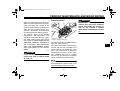
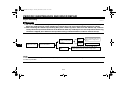
EAU10430
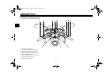
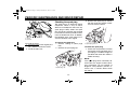
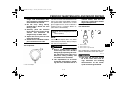
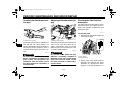
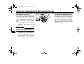
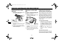
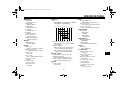
Controls and instruments
1. Clutch lever (page 3-5)
2. Left handlebar switches (page 3-4)
3. Multi-function display (page 3-3)
4. Main switch/steering lock (page 3-1)
5. Tachometer (page 3-3)
6. Right handlebar switches (page 3-4)
7. Throttle grip (page 6-15)
8. Brake lever (page 3-6)
U5D7E0E0.book Page 3 Tuesday, December 18, 2007 10:13 AM

INSTRUMENT AND CONTROL FUNCTIONS
3-1
3
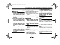
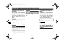
EAU10460
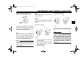
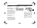
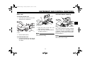
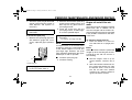
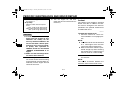
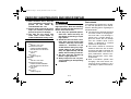
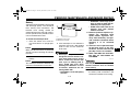
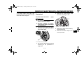
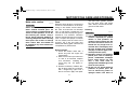
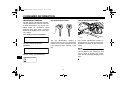
Main switch/steering lock
The main switch/steering lock controls
the ignition and lighting systems, and is
used to lock the steering. The various
positions are described below.
EAU36870
ON
All electrical circuits are supplied with
power, the meter lighting, taillight, li-
cense plate light and auxiliary lights
come on, and the engine can be start-
ed. The key cannot be removed.
NOTE:
The headlight comes on automatically
when the engine is started and stays on
until the key is turned to “OFF”, even if
the engine stalls.
EAU10660
OFF
All electrical systems are off. The key
can be removed.
EAU10690
LOCK
The steering is locked, and all electrical
systems are off. The key can be re-
moved.
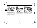
To lock the steering
1. Turn the handlebars all the way to
the left or right.
2. Push the key in from the “OFF” po-
sition, and then turn it to “LOCK”
while still pushing it.
3. Remove the key.
To unlock the steering
Push the key into the main switch, and
then turn it to “OFF” while still pushing
it.
WARNING
EWA10060
Never turn the key to “OFF” or
“LOCK” while the vehicle is moving,
otherwise the electrical systems will
be switched off, which may result in
loss of control or an accident. Make
sure that the vehicle is stopped be-
fore turning the key to “OFF” or
“LOCK”.
1. Push.
2. Turn.
1. Push.
2. Turn.
U5D7E0E0.book Page 1 Tuesday, December 18, 2007 10:13 AM

INSTRUMENT AND CONTROL FUNCTIONS
3-2
3
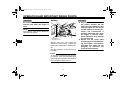
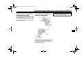
EAU11003
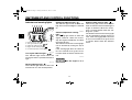
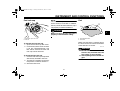
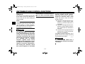
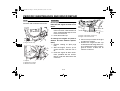
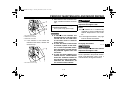
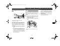
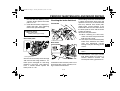
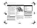
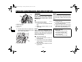
Indicator and warning lights
EAU11020
Turn signal indicator light “”
This indicator light flashes when the
turn signal switch is pushed to the left or
right.
EAU11060
Neutral indicator light “”
This indicator light comes on when the
transmission is in the neutral position.
EAU11080
High beam indicator light “”
This indicator light comes on when the
high beam of the headlight is switched
on.
EAUM2290
Coolant temperature warning
light “”
This warning light comes on when the
engine overheats. When this occurs,
stop the engine immediately and allow
the engine to cool.
The electrical circuit of the warning light
can be checked by turning the key to
“ON”.
If the warning light does not come on
for a few seconds, then go off, have a
Yamaha dealer check the electrical cir-
cuit.
CAUTION:
ECA10020
Do not operate the engine if it is
overheated.
EAU11500
Engine trouble warning light “”
This warning light comes on or flashes
when an electrical circuit monitoring the
engine is defective. When this occurs,
have a Yamaha dealer check the self-
diagnosis system.
The electrical circuit of the warning light
can be checked by turning the key to
“ON”. If the warning light does not come
on for a few seconds, then go off, have
a Yamaha dealer check the electrical
circuit.
1. Neutral indicator light “”
2. Turn signal indicator light “”
3. High beam indicator light “”
4. Engine trouble warning light “”
5. Coolant temperature warning light “”
U5D7E0E0.book Page 2 Tuesday, December 18, 2007 10:13 AM

INSTRUMENT AND CONTROL FUNCTIONS
3-3
3
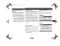
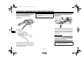
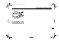
EAU11872
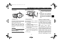
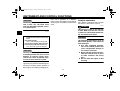
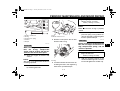
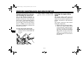
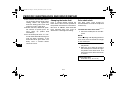
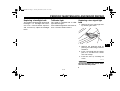
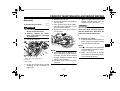
Tachometer
The electric tachometer allows the rider
to monitor the engine speed and keep it
within the ideal power range.
When the key is turned to “ON”, the ta-
chometer needle will sweep once
across the r/min range and then return
to zero r/min in order to test the electri-
cal circuit.
CAUTION:
ECA10031
Do not operate the engine in the ta-
chometer red zone.
Red zone: 10000 r/min and above
EAUM2301
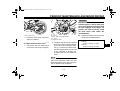
Multi-function display
The multi-function display is equipped
with the following:
●a speedometer (which shows the
riding speed)
●an odometer (which shows the to-
tal distance traveled)
●two tripmeters (which show the
distance traveled since they were
last set to zero)
●a fuel reserve tripmeter (which
shows the distance traveled since
the fuel level warning light came
on)
●a fuel meter
NOTE:
●Be sure to turn the key to “ON” be-
fore using the “RESET/ SELECT”
button.
●For the U.K. only: To switch the
speedometer and odometer/trip-
meter displays between kilometers
and miles, press the “RESET/SE-
LECT” button for at least eight sec-
onds.
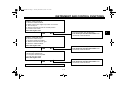
Odometer and tripmeter modes
A brief push (less than one second) on
the “RESET/SELECT” button switches
the display between the odometer
mode “ODO” and the tripmeter modes
“TRIP 1” and “TRIP 2” in the following
order:
ODO → TRIP 1 → TRIP 2 → ODO
When approximately 1.6 L (0.42 US
gal)(0.35 Imp.gal) of fuel remains in the
fuel tank, the odometer display will au-
tomatically change to the fuel reserve
tripmeter mode “F-TRIP” and start
counting the distance traveled from that
point, and the last segment of the fuel
meter will start flashing. In that case,
pushing the “RESET/SELECT” button
1. Tachometer
2. Tachometer red zone
1. Multi-function display
2. “RESET/SELECT” button
U5D7E0E0.book Page 3 Tuesday, December 18, 2007 10:13 AM

INSTRUMENT AND CONTROL FUNCTIONS
3-4
3
switches the display between the vari-
ous tripmeter and odometer modes in
the following order:
F-TRIP → TRIP 1 → TRIP 2 → ODO →
F-TRIP
To reset a tripmeter, select it by push-
ing the “RESET/SELECT” button briefly
(less than one second), and then push
the button again for at least three sec-
onds while the selected tripmeter is
flashing. If you do not reset the fuel re-
serve tripmeter manually, it will reset it-
self automatically and the display will
return to the prior mode after refueling
and traveling 5 km (3 mi).
Fuel meter
The fuel meter indicates the amount of
fuel in the fuel tank. The display seg-
ments of the fuel meter disappear to-
wards “E” (Empty) as the fuel level
decreases. When the last fuel meter
segment starts flashing, refuel as soon
as possible.
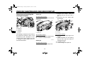
EAU12347
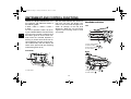
Handlebar switches
Left
Right
1. Fuel meter
1. Pass switch “PASS”
2. Dimmer switch “/”
3. Turn signal switch “/”
4. Horn switch “”
1. Engine stop switch “/”
2. Start switch “”
U5D7E0E0.book Page 4 Tuesday, December 18, 2007 10:13 AM

INSTRUMENT AND CONTROL FUNCTIONS
3-5
3
EAU12360
Pass switch “PASS”
Press this switch to flash the headlight.
EAU12400
Dimmer switch “/”
Set this switch to “” for the high
beam and to “” for the low beam.
EAU12460
Turn signal switch “/”
To signal a right-hand turn, push this
switch to “”. To signal a left-hand
turn, push this switch to “”. When re-
leased, the switch returns to the center
position. To cancel the turn signal
lights, push the switch in after it has re-
turned to the center position.
EAU12500
Horn switch “”
Press this switch to sound the horn.
EAU12660
Engine stop switch “/”
Set this switch to “” before starting
the engine. Set this switch to “” to
stop the engine in case of an emergen-
cy, such as when the vehicle overturns
or when the throttle cable is stuck.
EAU12710
Start switch “”
Push this switch to crank the engine
with the starter.
CAUTION:
ECA10050
See page 5-1 for starting instruc-
tions prior to starting the engine.
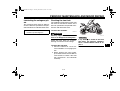
EAU12820
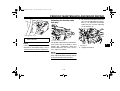
Clutch lever
The clutch lever is located at the left
handlebar grip. To disengage the
clutch, pull the lever toward the handle-
bar grip. To engage the clutch, release
the lever. The lever should be pulled
rapidly and released slowly for smooth
clutch operation.
The clutch lever is equipped with a
clutch switch, which is part of the igni-
tion circuit cut-off system. (See page
3-10.)
1. Clutch lever
U5D7E0E0.book Page 5 Tuesday, December 18, 2007 10:13 AM

INSTRUMENT AND CONTROL FUNCTIONS
3-6
3
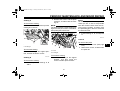
EAU12870
Shift pedal
The shift pedal is located on the left
side of the engine and is used in com-
bination with the clutch lever when
shifting the gears of the 6-speed con-
stant-mesh transmission equipped on
this motorcycle.
EAU12890
Brake lever
The brake lever is located at the right
handlebar grip. To apply the front
brake, pull the lever toward the handle-
bar grip.
EAU12941
Brake pedal
The brake pedal is on the right side of
the motorcycle. To apply the rear
brake, press down on the brake pedal.
1. Shift pedal 1. Brake lever 1. Brake pedal
U5D7E0E0.book Page 6 Tuesday, December 18, 2007 10:13 AM
Page is loading ...
Page is loading ...
Page is loading ...
Page is loading ...
Page is loading ...
Page is loading ...
Page is loading ...
Page is loading ...
Page is loading ...
Page is loading ...
Page is loading ...
Page is loading ...
Page is loading ...
Page is loading ...
Page is loading ...
Page is loading ...
Page is loading ...
Page is loading ...
Page is loading ...
Page is loading ...
Page is loading ...
Page is loading ...
Page is loading ...
Page is loading ...
Page is loading ...
Page is loading ...
Page is loading ...
Page is loading ...
Page is loading ...
Page is loading ...
Page is loading ...
Page is loading ...
Page is loading ...
Page is loading ...
Page is loading ...
Page is loading ...
Page is loading ...
Page is loading ...
Page is loading ...
Page is loading ...
Page is loading ...
Page is loading ...
Page is loading ...
Page is loading ...
Page is loading ...
Page is loading ...
Page is loading ...
Page is loading ...
Page is loading ...
Page is loading ...
Page is loading ...
Page is loading ...
Page is loading ...
Page is loading ...
Page is loading ...
Page is loading ...
Page is loading ...
Page is loading ...
Page is loading ...
Page is loading ...
Page is loading ...
Page is loading ...
Page is loading ...
Page is loading ...
-
 1
1
-
 2
2
-
 3
3
-
 4
4
-
 5
5
-
 6
6
-
 7
7
-
 8
8
-
 9
9
-
 10
10
-
 11
11
-
 12
12
-
 13
13
-
 14
14
-
 15
15
-
 16
16
-
 17
17
-
 18
18
-
 19
19
-
 20
20
-
 21
21
-
 22
22
-
 23
23
-
 24
24
-
 25
25
-
 26
26
-
 27
27
-
 28
28
-
 29
29
-
 30
30
-
 31
31
-
 32
32
-
 33
33
-
 34
34
-
 35
35
-
 36
36
-
 37
37
-
 38
38
-
 39
39
-
 40
40
-
 41
41
-
 42
42
-
 43
43
-
 44
44
-
 45
45
-
 46
46
-
 47
47
-
 48
48
-
 49
49
-
 50
50
-
 51
51
-
 52
52
-
 53
53
-
 54
54
-
 55
55
-
 56
56
-
 57
57
-
 58
58
-
 59
59
-
 60
60
-
 61
61
-
 62
62
-
 63
63
-
 64
64
-
 65
65
-
 66
66
-
 67
67
-
 68
68
-
 69
69
-
 70
70
-
 71
71
-
 72
72
-
 73
73
-
 74
74
-
 75
75
-
 76
76
-
 77
77
-
 78
78
-
 79
79
-
 80
80
-
 81
81
-
 82
82
-
 83
83
-
 84
84


Ask a question and I''ll find the answer in the document
Finding information in a document is now easier with AI
Related papers
-
Yamaha 2008 YZF-R6X Owner's manual
-
-
-
-
-
-
-
-
-
