Page is loading ...

CAME S.p.A.
Via Martiri Della Libertà, 15
31030 - Dosson di Casier
Treviso - Italy
XDV/304A
250 m max.
250 m max.
250 m max.
2
25
XA/300LR+
XAV/300
SW1
SW2 SW4
SW3
M1
M3
XDV/304A
M2
B3
+
-
B4
B1
B2
+
-
B OUT
+
-
M3 SW5
SW1
SW2 SW4
SW3
M1
M3
XDV/304A
M2
B3
+
-
B4
B1
B2
+
-
M3 SW5
1
SW1
SW2 SW4
SW3
M1
M3
XDV/304A
M2
B3
+
-
B4
B1
B2
+
-
M3 SW5
B IN
+
-
B OUT
+
-
B IN
+
-
B OUT
+
-
B IN
+
-
SW5
SW1
+
B IN
+
M1
M3
B OUT
+
B1
+
B2
B3
B4
SW2 SW3 SW4
M2
100 m max.
2
16
SW1
SW2 SW4
SW3
M1
M3
XDV/304A
M2
B3
+
-
B4
B1
B2
+
-
B OUT
+
-
M3 SW5
SW1
SW2 SW4
SW3
M1
M3
XDV/304A
M2
B3
+
-
B4
B1
B2
+
-
M3 SW5
1
SW1
SW2 SW4
SW3
M1
M3
XDV/304A
M2
B3
+
-
B4
B1
B2
+
-
M3 SW5
B IN
+
-
B OUT
+
-
B IN
+
-
B OUT
+
-
B IN
+
-
X2
250 m max.
XA/300LR+
XAV/300
1
15
SW1
SW2 SW4
SW3
M1
M3
XDV/304A
(10 XDV/304 max.)
M2
B3
+
-
B4
B1
B2
+
-
B OUT
+
-
M3 SW5
SW1
SW2 SW4
SW3
M1
M3
XDV/304A
M2
B3
+
-
B4
B1
B2
+
-
M3 SW5
B IN
+
-
B OUT
+
-
B IN
+
-
1
SW4
SW3
SW1 SW2
M2 M1
M3
B IN
B OUT
SW5
XDV/304A
X2
2
SW4
SW3
SW1 SW2
M2 M1
M3
B IN
B OUT
SW5
XDV/304A
10
SW4
SW3
SW1 SW2
M2 M1
M3
B IN
B OUT
XDV/304A
SW5
100 m max.
148540
37
B2
B1
+
-
B4
B3
+
-
B2
B1
+
-
B4
B3
+
-
B2
B1
+
-
B4
B3
+
-
+
-
+
-
+
-
+
-
+
-
+
-
43,5
45
7,5 57
140
106
64,5
145
IT
Italiano
EN
English
FR
Français
RU
Pусский
FB00331M4A
FB00331M4A - 05/2018

FB00331M4A - 05/2018
ITALIANO
Avvertenze generali
• Leggere attentamente le istruzioni prima di iniziare l’installa-
zione ed eseguire gli interventi come specifi cato dal costruttore.
• L’installazione, la programmazione, la messa in servizio e la
manutenzione del prodotto deve essere e ettuata soltanto da
personale tecnico qualifi cato ed opportunamente addestrato nel
rispetto delle normative vigenti ivi comprese le osservanze sulla
prevenzione infortuni e lo smaltimento imballaggi.
• Le schede elettroniche possono essere seriamente danneg-
giate dalle scariche elettrostatiche: qualora vi sia bisogno di ma-
neggiarle indossare idonei indumenti e calzature antistatiche o,
almeno, assicurarsi preventivamente di aver rimosso ogni carica
residua toccando con la punta delle dita una superfi cie metallica
connessa all’impianto di terra (es. lo chassis di un elettrodome-
stico).
• Prima di e ettuare qualunque operazione di pulizia o di manu-
tenzione, togliere l’alimentazione al dispositivo.
• L’apparecchio dovrà essere destinato unicamente all’uso per il
quale è stato espressamente concepito.
• Il costruttore non può comunque essere considerato respon-
sabile per eventuali danni derivanti da usi impropri, erronei ed
irragionevoli.
Descrizione
Apparecchio per la distribuzione del segnale video modu-
lato su 4 linee, per sistema X2.
Dispone di 5 ponticelli di chiusura impedenza di linea. I
ponticelli SW1, SW2, SW3 e SW4 sono relativi rispetti-
vamente alle linee 1, 2, 3 e 4 (i ponticelli, normalmente
inseriti, devono essere rimossi quando viene utilizzata la
relativa uscita per il collegamento di un derivato interno
videocitofonico); il ponticello SW5 è relativo alla linea prin-
cipale.
Qualora le uscite 1, 2, 3 e 4 del distributore video siano
utilizzate per il collegamento di un citofono, i ponticelli
SW1, SW2, SW3, SW4 devono rimanere inseriti.
È possibile collegare fi no a un massimo di 30 distributori,
utilizzando un amplifi catore di segnale video XDV/304A
ogni 10 distributori XDV/304.
Morsettiera M1
B1 Uscita linea 1
+
–Uscita alimentazione
B2 Uscita linea 2
Morsettiera M2
B3 Uscita linea 3
+
–Uscita alimentazione
B4 Uscita linea 4
Morsettiera M3
+
–Ingresso alimentazione
B IN Ingresso linea principale
+
–Uscita alimentazione
B OUT Uscita linea principale
Dati tecnici
Tipo XDV/304A
Alimentazione (V DC) 14÷18
Corrente assorbita max. (
mA
)
60
Grado di protezione (IP) 30
Attenuazione max. uscita video
passante per ingresso/uscita (dB) 0,6
Attenuazione max. uscita video
per ingresso/uscita (dB) 1
Tipo XDV/304A
Temperatura di funzionamento (°C) 0 ÷ +35
Temperatura di stoccaggio (°C) -25 ÷ +70
Installazione
Il dispositivo, con attacco per guide DIN, può essere instal-
lato senza coprimorsetti in un armadio metallico oppure a
parete applicando i coprimorsetti.
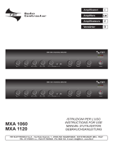
Schemi di installazione
In impianto con Sistema 300.
Somma totale del cavo utilizzato: 1.000 m.
In impianto con Sistema X2.
Somma totale del cavo utilizzato: 600 m.
In impianto residenziale con Sistema 300 e X2.
Somma totale del cavo utilizzato per collegare l’alimenta-
tore XA/300LR ai blocchi più il cavo utilizzato nel blocco:
1.000 m.
Dichiarazione . CAME S.p.A., dichiara che questo dispositivo è con-
forme alle direttive 2014/30/UE e 2006/95/EC. Originali su richiesta.
Dismissione e smaltimento. Non disperdere nell’ambiente l’imballag-
gio e il dispositivo alla fi ne del ciclo di vita, ma smaltirli seguendo le
norme vigenti nel paese di utilizzo del prodotto. I componenti riciclabili
riportano simbolo e sigla del materiale.
I DATI E LE INFORMAZIONI INDICATE IN QUESTO MANUALE SONO DA RITENERSI
SUSCETTIBILI DI MODIFICA IN QUALSIASI MOMENTO E SENZA OBBLIGO DI PRE-
AVVISO. LE MISURE, SE NON DIVERSAMENTE INDICATO, SONO IN MILLIMETRI.
РУССКИЙ
Общие предупреждения
• Перед началом работ по установке внимательно озна-
комьтесь с инструкциями и выполните установку согласно
рекомендациям производителя.
Установка, программирование, ввод в эксплуатацию и
обслуживание продукта должны выполняться только ква-
лифицированным и специально обученным персоналом
ссоблюдением действующих стандартов, включая требо-
вания по охране труда, технике безопасности и утилизации
упаковки.
• Электронные компоненты могут быть серьезно повре-
ждены разрядом статического электричества: при обслу-
живании используйте специальную одежду и антистати-
ческую обувь. В крайнем случае, убедитесь в отсутствии
заряда, коснувшись пальцами заземленных металлических
поверхностей (например, корпуса бытового прибора).
Перед чисткой или техническим обслуживанием следует
отсоединять устройство от источника электропитания.
• Устройства следует использовать только вцелях, для ко-
торых они предназначены.
• Производитель не несет никакой ответственности за лю-
бые повреждения, возникшие в результате неправильного,
некорректного или неоправданного использования.
Описание
Устройство для распределения видеосигнала, на 4 ли-
нии, для системы X2.
Имеет 5 перемычек закрытия полного сопротивления
линии. Перемычки SW1, SW2, SW3 и SW4 соответ-
ственно связаны с линиями 1, 2, 3 и 4 (перемычки,
как правило, вставленные, должны быть удалены,
когда для подключения абонентского устройства ис-
пользуется соответствующий выход); перемычка SW5
связана с основной линией.
Если выходы 1, 2, 3 и 4 видео распределителя исполь-
зуется для подключения домофона, перемычки SW1,
SW2, SW3, SW4 должны быть оставлены.
Можно подсоединить не более 30 распределителей,
используя усилитель видеосигнала XDV/304A для
каждых 10 распределителей XDV/304.
Клеммная колодка М1
B1 Выход линии 1
+
–Выход питания
B2 Выход линии 2
Клеммная колодка М2
B3 Выход линии 3
+
–Выход питания
B4 Выход линии 4
Клеммная колодка М3
+
–Вход питания
B IN Вход основной линии
+
–Выход питания
B OUT Выход основной линии
Технические данные
Тип XDV/304A
Питание (В пост. тока) 14÷18
Потребление тока макс. (
мА
)
60
Класс защиты 30
Макс. затухание видеовход
пропускания на вход/выход (дБ) 0,6
Макс. затухание видеовход на
вход/выход (дБ) 1
Тип XDV/304A
Рабочая температура (°C) 0 ÷ +35
Температура хранения (°C) -25 ÷ +70
Установка
Устройство, с подключением к рейке DIN, может быть
установлено без защитных крышек клеммных колодок
в металлическом корпусе или на стене с защитной
крышкой.
Схемы установки
В системах с Sistema 300.
Общая длина используемого кабеля: 1 000 м.
В системах с Sistema X2.
Общая длина используемого кабеля: 600 м.
В системах жилых домов с Sistema 300 и X2.
Общая длина используемого кабеля для подсоедине-
ния блока питания XA/300LR к блокам, плюс кабель в
блоках: 1 000 м.
Декларация . CAME S.p.A. заявляет, что данное устройство
соответствует требованиям Директивы 2014/30/UE и 2006/95/ЕС.
Оригиналы предоставляется по запросу.
Прекращение использования и утилизация. Не выбрасывайте
упаковку и устройство в конце жизненного цикла, утилизируйте их
в соответствии с действующими в стране использования продукта
нормами. Компоненты, пригодные для повторного использования,
отмечены специальным символом с обозначением материала.
ДАННЫЕ И ИНФОРМАЦИЯ, СОДЕРЖАЩАЯСЯ В ДАННОМ РУКОВОДСТВЕ,
МОГУТ БЫТЬ ИЗМЕНЕНЫ В ЛЮБОЕ ВРЕМЯ БЕЗ ПРЕДВАРИТЕЛЬНОГО
УВЕДОМЛЕНИЯ. РАЗМЕРЫ, ЕСЛИ НЕ УКАЗАНО ИНОЕ, В МИЛЛИМЕТРАХ.
ENGLISH
General precautions
• Read the instructions carefully before beginning the installa-
tion and carry out the actions as specifi ed by the manufacturer.
• The installation, programming, commissioning and main-
tenance of the product must be carried out only by qualifi ed
technical personnel, correctly trained with regard to respecting
the regulations in force, including the implementation of acci-
dent-prevention measures and the disposal of packaging.
• The electronic circuit boards can be seriously damaged by
electrostatic discharge. Should you need to handle them, wear
appropriate clothing and anti-static shoes or at least be sure
to have discharged any residual charge by touching a metal
surface connected to the earthing system (e.g. the body of a
domestic appliance) with the tip of your fi ngers.
• Before carrying out any cleaning or maintenance operation,
disconnect the device from the power supply.
• The equipment must be used solely for the purpose for which
it was expressly designed.
• The manufacturer declines all liability for any damage as a
result of improper, incorrect or unreasonable use.
Description
This device is used to distribute video signal modulated
over 4 lines for the X2 system.
It has 5 line impedance closing jumpers. The jumpers
SW1, SW2, SW3 and SW4 relate respectively to lines 1,
2, 3 and 4 (the jumpers, inserted as normal, should be
removed when the relative output is used to connect an
internal video receiver); jumper SW5 relates to the main
line.
Should the outputs 1, 2, 3 and 4 of the video distributor be
used to connect a receiver, the jumpers SW1, SW2, SW3
and SW4 should remain inserted.
Up to 30 distributors may be connected, by using an XD-
V/304A video-signal amplifi er every 10 distributors.
Terminal board M1
B1 Output line 1
+
–Power supply output
B2 Output line 2
Terminal board M2
B3 Output line 3
+
–Power supply output
B4 Output line 4
Terminal board M3
+
–Power supply input
B IN Main line input
+
–Power supply output
B OUT Main line output
Technical data
Type XDV/304A
Power supply (V DC) 14-18
Max. absorbed current (
mA
)
60
Protection rating (IP) 30
Max. attenuation video output
passing through input/output (dB) 0.6
Max. attenuation video output
through input/output (dB) 1
Operating temperature (°C) 0 to +35
Storage temperature (°C) -25 to +70
Installation
The device, with DIN rail attachment, can be installed
without any terminal covers in a metal cabinet or mounted
on the wall using terminal covers.
Installation diagrams
In a set-up with 300 system.
Total cable used: 1,000 m.
In a set-up with X2 system.
Total cable used: 600 m.
In residential set-ups with 300 and X2 systems.
Total cable used to connect the XA/300LR power supply
to the blocks, plus the cable used in the block: 1,000 m.
Declaration. CAME S.p.A. declares that this device complies with
Directives 2014/30/UE and 2006/95/EC. Originals upon request.
Decommissioning and disposal. Dispose of the packaging material
and the device at the end of its life cycle responsibly, in compliance
with the laws in force in the country where the product is used. The
recyclable components are marked with a symbol and the material's
ID marker.
THE DATA AND INFORMATION SHOWN IN THIS MANUAL ARE TO BE CON-
SIDERED AS SUBJECT TO CHANGE AT ANY TIME AND WITHOUT THE NEED
FOR ANY ADVANCE WARNING. MEASUREMENTS, UNLESS OTHERWISE INDIC-
ATED, ARE IN MILLIMETRES.
FRANÇAIS
Instructions générales
• Lire attentivement les instructions avant de commencer
l'installation et e ectuer les interventions comme indiqué par
le fabricant.
• L'installation, la programmation, la mise en service et l'entre-
tien du produit ne doivent être e ectués que par un personnel
technique qualifi é et convenablement formé, conformément
aux normes en vigueur, y compris les dispositions concernant
la prévention des accidentset l'élimination des emballages.
• Les cartes électroniques peuvent être sérieusement en-
dommagées par les décharges électrostatiques : au cas où il
serait nécessaire de les manipuler, porter des vêtements adé-
quats et des chaussures anti-statiques ou bien,s'assurer au
préalable d'avoir éliminé toute charge résiduelle en touchant
du bout des doigts une surface métallique connectée à l'instal-
lation de terre (ex. le châssis d'un électroménager).
• Avant d'e ectuer toute opération de nettoyage ou d'entretien,
débrancher l'alimentation électrique de l'appareil.
• L'appareil doit être uniquement utilisé dans le but pour lequel
il a été conçu.
• Le fabricant ne peut toutefois être tenu pour responsable des
éventuels dommages qui naîtraient d'une utilisation erronée ou
déraisonnable.
Description
Appareil pour la distribution du signal vidéo modulé sur 4
lignes, pour système X2.
Il dispose de 5 cavaliers de fermeture de l'impédance de
ligne. Les cavaliers SW1, SW2, SW3 et SW4 sont res-
pectivement relatifs aux lignes 1, 2, 3 et 4 (les cavaliers,
généralement insérés, doivent être retirés lorsque la re-
lative sortie est utilisée pour le branchement d'un poste
interne du portier vidéo) ; le cavalier SW5 est relatif à la
ligne principale.
Si les sorties 1, 2, 3 et 4 du distributeur vidéo sont utili-
sées pour le branchement d'un interphone, les cavaliers
SW1, SW2, SW3, SW4 doivent rester insérés.
Il est possible de brancher jusqu’à 30 distributeurs en uti-
lisant un amplifi cateur de signal vidéo XDV/304A tous les
10 distributeurs XDV/304.
Bornier M1
B1 Sortie ligne 1
+
–Sortie alimentation
B2 Sortie ligne 2
Bornier M2
B3 Sortie ligne 3
+
–Sortie alimentation
B4 Sortie ligne 4
Bornier M3
+
–Entrée alimentation
B IN Entrée ligne principale
+
–Sortie alimentation
B OUT Sortie ligne principale
Données techniques
Type XDV/304A
Alimentation (Vcc) 14÷18
Courant absorbé max. (
mA
)
60
Indice de protection (IP) 30
Atténuation max. sortie vidéo
passante pour entrée/sortie (dB) 0,6
Atténuation max. sortie vidéo pour
entrée/sortie (dB) 1
Type XDV/304A
Température de fonctionnement
(°C) 0 ÷ +35
Température de stockage (°C) -25 ÷ +70
Installation
Le dispositif, avec raccord pour rails DIN, peut être installé
sans cache-bornes dans une armoire métallique ou bien
au mur en appliquant les cache-bornes.
Schémas d'installation
Sur installation avec Système 300.
Somme totale du câble utilisé : 1000 m
Sur installation avec Système X2.
Somme totale du câble utilisé : 600 m
Sur installation résidentielle avec Système 300 et
X2.
Somme totale du câble utilisé pour brancher l'alimenta-
teur XA/300LR sur les blocs plus le câble utilisé sur le
bloc : 1000 m
Déclaration . CAME S.p.A., déclare que ce dispositif est conforme
aux directives 2014/30/UE et 2006/95/CE. Documents originaux fournis
sur simple demande.
Démantèlement et élimination. Ne pas jeter les emballages et l'ap-
pareil dans la nature à la fi n du cycle de vie, mais veuillez les éliminer
conformément à la réglementation en vigueur dans le Pays d'utilisation
du produit. Les composants recyclables portent le symbole et le sigle
du matériau.
LES DONNÉES ET INFORMATIONS DE CE MANUEL SONT CONSIDÉRÉES
COMME SUSCEPTIBLES DE MODIFICATIONS À TOUT MOMENT ET SANS
PRÉAVIS. LES MESURES, SAUF AUTRES INDICATIONS, SONT EXPRIMÉES EN
MILLIMÈTRES.
/