FA00825M4A - ver. 1 - 09/2017
General Precautions
WARNING. Important safety instructions. READ CAREFULLY.
• Installation, programming, commissioning and mainte-
nance must only be carried out by qualified, expert sta and
in full compliance with the applicable law.
• Wear antistatic protective clothing and footwear when
working on the control board.
• Keep these precautions.
• Always cut o the mains power when doing cleaning and
maintenance jobs.
• This product must only be used for the purpose for which
it was designed. Any other use is dangerous.
• The manufacturer declines all liability for any damage as a
result of improper, incorrect or unreasonable use.
Description
Receiver for interfacing radio accessories and wired safety
systems. When connected to an alarm control unit, it allows
you to expand the system up to 32 radio inputs, 8 remote
controls and 1 radio siren. The radio input status is replicated
over the 8 configurable wired channels.
The display shows which inputs have generated the alarm.
Ensure that the power supplied to the device has current
limited to 2A.
Description of parts A
1 Display
2 Warning LEDs
C Alphanumeric keypad
4 Opening/breakage-resistant tamper
E F Terminal boards
G RESET button
8 Jumper for enabling / disabling the tamper resistant me-
chanism
Description of the terminals
+ 12V - Device power supply 9-15 Vcc
+ Power supply
ON/OFF Input for connecting the ON/OFF status of the
wired control unit
SIREN Input for connecting the siren status, used to con-
trol the radio siren
TAMPER Shows the opening/breakage-resistant tamper
status
01 to 08 8 output channels
T
(tamper)
The output is activated when an associated
radio device has been tampered with
S
(Supervision)
The output is activated when a device does
not respond for the supervision time set
B
(Battery)
The output is activated when a device sig-
nals that the battery is flat
J
(Jamming)
The output is activated when the receiver
detects that both frequencies are masked
Description of LEDs A
LED Status Meaning
(green) 〇It means there are open entrances associat-
ed with the receiver.
●It means there are NO open entrances asso-
ciated with the receiver.
(green) 〇It means that the wired control unit is dis-
connected.
●It means that the wired control unit is en-
gaged.
(red) 〇It means that the receiver does not have any
alarms or unresolved alarm memories
●It means that there is at least one input with
an alarm active
◉
It means that there was an alarm condition.
The message is removed when the system
is next armed
(yellow) 〇It means that there are no faults in the sys-
tem.
●
It means there is a failure. When the “Mask
state” function has been activated, it means
that there is an event to display
◉It means that there is a fault saved in the
memory
〇 = O | ● = On | ◉ = Flashing
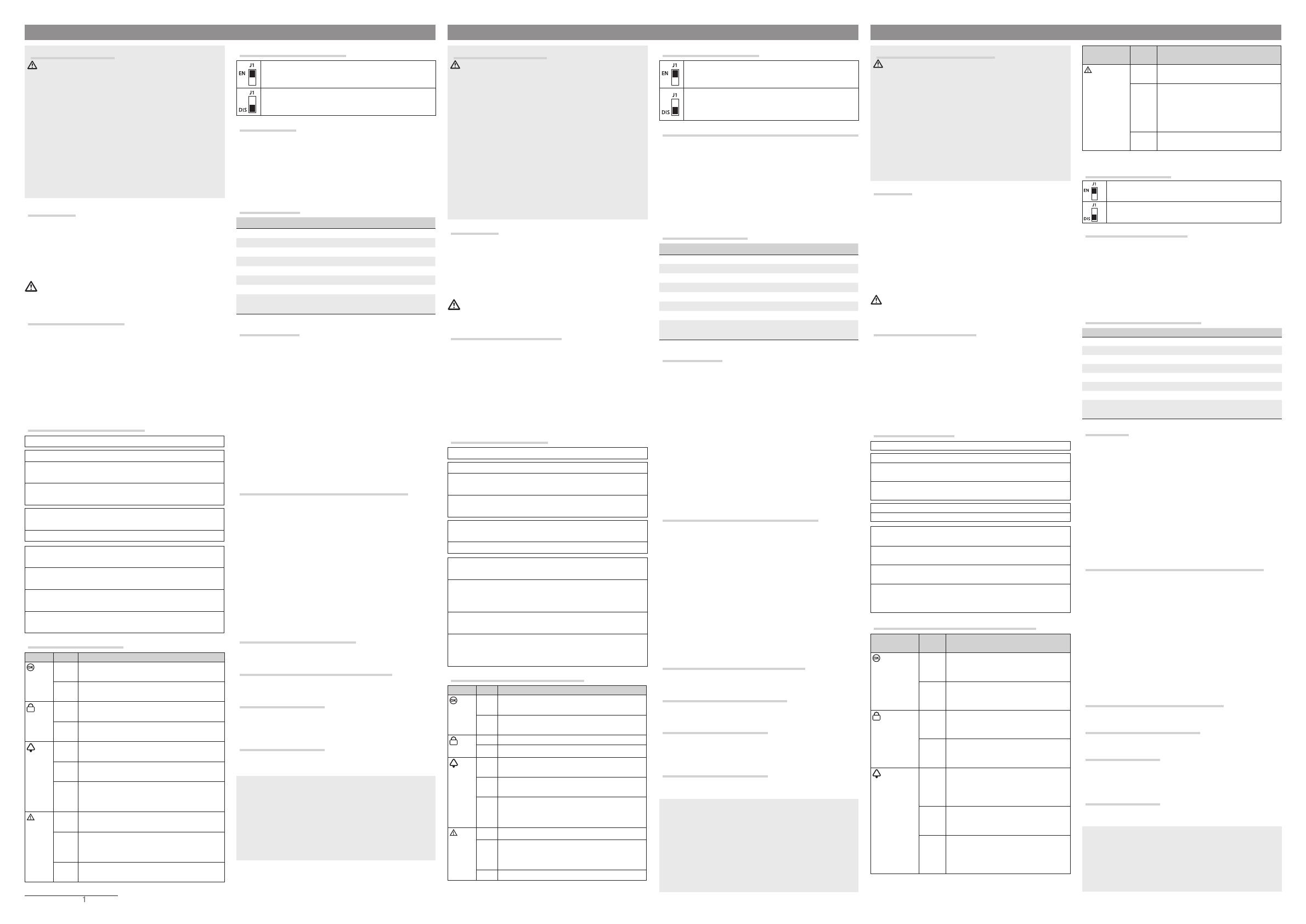
Description of the jumper
Enabling the tamper-resistant mechanism
Disabling the tamper-resistant mechanism and
enabling only the opening-resistant mechanism
RESET button
To reset the user and installer codes to the default values:
1- Press and hold the * and # buttons and then the reset but-
ton,
2- Wait for the message to show on the display requesting the
codes to be reset and release the *and # buttons,
3- Confirm the cancellation request by pressing the * button.
Technical data
Type PXWRXU
Power supply (V DC) 9 to 15
Max consumption (mA) 400
Frequency (MHz) 433.92 / 868.65
Radio signal power (dBm) <10
Operating temperature (°C) -10 to +40
Dimensions (mm) 260x130x42
Installation height (m) 1.5
Conformance with applicable laws: EN 50131-5-3, Grade 2,
environmental class II
Installation B
The receiver must be fitted in an easily accessible area, close
to the alarm control unit but away from metal objects that may
interfere with the radio signal.
Open the cover by unscrewing the screw on the side using a
screwdriver 1.
Lift the lid on the dialler 2.
Use the template provided and mark the position of the holes,
ensuring that the wall is flat in the chosen position 3.
Make a hole in the wall for the dialler and use the necessary
plugs to fix the container.
Fix the bottom of the receiver to the wall, ensuring that the
opening/breakage-resistant tamper can be correctly triggered
4.
Connections to the wired control unit C
1 Central power supply output
B Central status positive output
C Siren control positive output
D Tamper line
E Central input
F Central shared terminal for input
F Central shared terminal for inputs
H Jamming central inputs
I Battery central input
J Supervision central inputs
K Tamper central inputs
Connections between the tamper, receiver out-
puts and the control unit D
Connections between the power supply, re-
ceiver inputs and the control unit E
Connections between the receiver output and
control unit input F
Normally open (N.O.): Open = Stand-by; Closed = Alarm
Connections between the receiver output and
control unit input G
Normally Closed (N.C.): Closed = Stand-by; Open = Alarm
The product complies with the relevant directives in force.
Decommissioning and disposal. Dispose of the packaging and the
device responsibly at the end of its life cycle, in compliance with the
laws in force in the country where the product is used. The recyclable
components are marked with a symbol and the material's ID marker.
THE DATA AND INFORMATION SHOWN IN THIS MANUAL ARE TO BE
CONSIDERED AS SUBJECT TO CHANGE AT ANY TIME AND WITHOUT
THE NEED FOR ANY ADVANCE WARNING. MEASUREMENTS, UNLESS
OTHERWISE INDICATED, ARE IN MILLIMETRES.
ENGLISH
Instructions générales
ATTENTION ! Instructions importantes pour la sécurité des
personnes : À LIRE ATTENTIVEMENT !
• L’installation, la programmation, la mise en service et l'entre-
tien doivent être eectués par du personnel qualifié et dans le
plein respect des normes en vigueur.
• Porter des vêtements et des chaussures antistatiques avant
d'intervenir sur la carte électronique.
• Conserver ces instructions.
• Toujours couper le courant électrique durant les opérations de
nettoyage ou d'entretien.
• Ce produit ne devra être destiné qu'à l'utilisation pour laquelle
il a été expressément conçu. Toute autre utilisation est à consi-
dérer comme dangereuse.
• Le fabricant décline toute responsabilité en cas d'éventuels
dommages provoqués par des utilisations impropres, incorrectes
et déraisonnables.
Description
Récepteur pour l’interfaçage d’accessoires radio à des sys-
tèmes de sécurité filaires. Raccordé à des centrales d’alarme,
il permet d’eectuer l’expansion du système jusqu’à 32 en-
trées, 8 émetteurs et 1 sirène radio. L’état des entrées radio
est répliqué sur les 8 canaux filaires configurables.
L’acheur permet de visualiser les entrées ayant généré l’alarme.
S’assurer que l’alimentation fournie au dispositif prévoit
bien une limitation du courant ne dépassant pas 2 A.
Description des parties A
1 Acheur
2 Voyants de signalisation LED
C Clavier alphanumérique
4 Autoprotection anti-arrachement et anti-sabotage
E F Borniers
G Touche RàZ
8 Cavalier pour activation/désactivation autoprotection an-
ti-arrachement
Description des bornes
+ 12V - Alimentation dispositif 9-15 VDC
+ Alimentation
ON/OFF Entrée pour la connexion de l’état ON/FF de la
centrale filaire
SIREN Entrée pour la connexion de l’état de la sirène et
pour commander la sirène audio
TAMPER Indique l’état de l’autoprotection anti-arrache-
ment et anti-sabotage
01-08 Sorties 8 canaux
T (autoprotec-
tion)
l’activation de la sortie a lieu quand un dis-
positif radio associé est en état de sabotage
S
(Supervision)
l’activation de la sortie a lieu quand un dis-
positif ne répond pas pendant le temps de
supervision configuré
B
(Batterie)
l’activation de la sortie a lieu quand un dis-
positif signale l’épuisement de la batterie
J
(Brouillage)
l’activation de la sortie a lieu quand le récep-
teur note que les deux fréquences utilisées
sont brouillées
Description des voyants LED A
LED État Indications
(verte) 〇Indique la présence d'entrées ouvertes asso-
ciées au récepteur.
●Indique l’absence d’entrées ouvertes asso-
ciées au récepteur.
(verte)
〇Indique que la centrale filaire est désactivée.
●Indique que la centrale filaire est activée.
(rouge) 〇Indique que le récepteur ne présente aucune
alarme et aucune mémoire d’alarmes pendantes.
●Indique qu’au moins une entrée est en état
d’alarme.
◉
Indique qu’une condition d’alarme a eu lieu.
La signalisation disparaîtra au prochain cycle
d’activation de l’installation.
(jaune)
〇Indique l’absence de pannes sur l’installation.
●
Indique la présence d'une panne. Indique, en
cas de fonction « Masquage état » activée, la
présence d'un événement à visualiser
◉Indique la présence d’une mémoire de panne
〇 = Éteinte | ● = Allumée | ◉ = Clignotante
Description du cavalier
Activation de l’autoprotection anti-arrachement
Désactivation de l’autoprotection anti-arrachement
et activation, uniquement, de l’autoprotection an-
ti-sabotage
Fonctionnalité de la touche de remise à zéro (RàZ)
Pour réinitialiser les codes utilisateur et installateur aux va-
leurs d’usine, procéder comme suit :
1- appuyer sur les touches * et # en les laissant enfoncées
puis appuyer sur la touche de remise à zéro ;
2- attendre que l’écran ache le message avec la demande
de réinitialisation des codes et relâcher les touches * et # ;
3- confirmer la demande de suppression en appuyant sur la
touche *.
Données techniques
Type PXWRXU
Alimentation (VDC) 9-15
Absorption max. (mA) 400
Fréquence (MHz) 433.92 / 868.65
Puissance signal radio (dBm) <10
Température de fonctionnement (°C) -10 à +40
Dimensions (mm) 260x130x42
Hauteur d'installation (m) 1,5
Conformité norme : EN 50131-5-3, Degré 2, Classe environ-
nementale II
Installation B
Le récepteur doit être installé dans une zone facilement ac-
cessible, près de la centrale d’alarme et à l’écart de tout objet
métallique pouvant interférer avec le signal radio.
Ouvrir le couvercle en dévissant la vis latérale à l’aide d’un
tournevis 1.
Soulever le couvercle du composeur 2.
Tracer, à l’aide du gabarit fourni, la position des trous de fixa-
tion en contrôlant qu’à l’endroit choisi le mur est bien plat 3.
Percer le mur à l’endroit où sera logé le composeur et intro-
duire les chevilles nécessaires à la fixation du boîtier.
Fixer le fond du récepteur au mur en contrôlant le déclenche-
ment correct de l’autoprotection anti-arrachement et anti-sa-
botage 4.
Raccordement à la centrale filaire C
1 Sortie alimentation centrale
B Sortie positive état centrale
C Sortie positive commande sirène
D Ligne autoprotection
E Entrée centrale
F Commun entrée centrale
G Commun entrée centrale
H Entrées centrale brouillage
I Entrées centrale batterie
J Entrées centrale supervision
K Entrées centrale autoprotection
Raccordement entre l’autoprotection, les sor-
ties du récepteur et la centrale D
Raccordement entre l’alimentation, les entrées
du récepteur et la centrale E
Raccordement entre la sortie du récepteur et
l’entrée de la centrale F
Normalement Ouvert (NO) : Ouvert = Repos ; Fermé = Alarme
Raccordement entre la sortie du récepteur et
l’entrée de la centrale G
Normalement Fermé (NF) : Fermé = Repos ; Ouvert = Alarme
Le produit est conforme aux directives de référence en vigueur.
Mise au rebut et élimination. Ne pas jeter l'emballage et le dispo-
sitif dans la nature au terme du cycle de vie de ce dernier, mais les
éliminer selon les normes en vigueur dans le pays où le produit est
utilisé. Le symbole et le sigle du matériau figurent sur les compo-
sants recyclables.
LES DONNÉES ET LES INFORMATIONS CONTENUES DANS CE MA-
NUEL SONT SUSCEPTIBLES DE SUBIR DES MODIFICATIONS À TOUT
MOMENT ET SANS AUCUN PRÉAVIS. LES DIMENSIONS SONT EXPRI-
MÉES EN MILLIMÈTRES, SAUF INDICATION CONTRAIRE.
FRANÇAIS
Общие правила безопасности
ВНИМАНИЕ! Важные правила техники безопасности: ПРО-
ЧИТАЙТЕ ВНИМАТЕЛЬНО! • Монтаж, программирование, ввод в
эксплуатацию и техническое обслуживание должны произво-
диться квалифицированным и опытным персоналом в полном
соответствии с требованиями действующих норм безопасности. •
Используйте антистатическую одежду и обувь при работе с элек-
троникой. • Храните данные инструкции. • Всегда отключайте
электропитание перед выполнением работ по чистке или техни-
ческому обслуживанию системы. • Это изделие должно использо-
ваться исключительно по назначению. Любое другое применение
рассматривается как опасное. • Фирма-изготовитель снимает с
себя всякую ответственность за ущерб, нанесенный неправиль-
ным, ошибочным или небрежным использованием изделия.
Описание
Радиоприемник для обеспечения взаимодействия беспрово-
дных аксессуаров с проводными системами охранной сигна-
лизации.
При подключении к контрольным панелям охранной сигнали-
зации устройство позволяет расширять систему до 32 беспро-
водных входов, 8 устройств радиоуправления и 1 беспрово-
дной сирены. Состояние беспроводных входов дублируется на
8 настраиваемых проводных каналах.
С помощью дисплея можно посмотреть, какие входы привели
к срабатыванию сигнализации.
Убедитесь в том, что электропитание устройства снабже-
но ограничителем тока не более 2 А.
Основные компоненты A
1 Дисплей
2 Светодиодный индикатор
C Буквенно-цифровая кнопочная панель
4 Датчик саботажа
E F Клеммные колодки
G Кнопка «СБРОС»
8 Перемычка для активации/отключения тампера снятия
со стены
Описание контактов
+ 12V - Электропитание устройства =9-15 В
+ Электропитание
ON/OFF Вход подключения статуса ВКЛ/ВЫКЛ проводной
контрольной панели
SIREN Вход подключения статуса сирены, используемый
для управления беспроводной сиреной
TAMPER Показывает статус датчика саботажа
01-08 Выходы, 8 каналов
T (Датчик са-
ботажа)
Выход активируется при саботаже связанно-
го с ним беспроводного устройства
S
(Контроль)
Выход активируется, когда устройство не от-
вечает в течение заданного периода времени
B
(Батарея)
Выход активируется, когда устройство сигна-
лизирует о разрядке батареи
J
(Глушение)
Выход активируется, когда приемник обна-
руживает, что обе используемые частоты
замаскированы
Описание светодиодных индикаторов A
LED-ИНДИКА-
ТОРЫ Статус Описание
(зеленый) 〇
Светодиодный индикатор указывает
на то, что некоторые из входов, при-
своенных радиоприемнику, открыты.
●
Светодиодный индикатор указывает
на то, что все входы, присвоенные
радиоприемнику, закрыты.
(зеленый) 〇
Светодиодный индикатор указывает
на то, что проводная контрольная па-
нель выключена.
●
Светодиодный индикатор указывает
на то, что проводная контрольная па-
нель включена.
(красный) 〇
Светодиодный индикатор указывает
на отсутствие активных тревожных
сигналов или событий в журнале
тревог.
●
Светодиодный индикатор указывает
на то, что как минимум один вход на-
ходится в состоянии тревоги.
◉
Светодиодный индикатор указывает
на активное состояние тревоги. Сиг-
нал сбрасывается при последующем
включении системы.
LED-ИНДИКА-
ТОРЫ Статус Описание
(желтый) 〇Светодиодный индикатор указывает
на отсутствие ошибок в системе.
●
Светодиодный индикатор сообщает
о наличии ошибки. При включенной
функции «Маскировка статуса» све-
тодиодный индикатор указывает на
наличие события для просмотра.
◉Светодиодный индикатор указывает
на наличие ошибки в журнале памяти.
〇 = Выключен | ● = Горит ровным светом | ◉ = Мигает
Описание перемычки
Активация тампера снятия со стены
Отключение тампера снятия со стены и активация
только тампера вскрытия
Функция кнопки «СБРОС»
Для восстановления кодов пользователей и установщиков по
умолчанию выполните следующее:
1 - нажмите и удерживайте кнопки *, # и следом кнопку
«Сброс»;
2 - дождитесь появления на дисплее сообщения с запросом
сброса кодов и отпустите кнопки * и #;
3 - подтвердите запрос удаления, нажав кнопку *.
Технические характеристики
Модель PXWRXU
Напряжение электропитания (=В) 9-15
Макс. потребляемый ток (мA) 400
Частота (МГц) 433,92 / 868,65
Мощность радиосигнала (дБм) <10
Диапазон рабочих температур(°C) -10 — +40
Габаритные размеры (мм) 260x130x42
Высота монтажа (м) 1,5
Соответствует стандарту EN 50131-5-3, класс 2, класс опас-
ности для окружающей средыII.
Монтаж B
Радиоприемник должен устанавливаться в доступном месте
недалеко от контрольной панели охранной сигнализации, вда-
ли от металлических предметов, способных стать источником
радиопомех. Откройте крышку, отвернув отверткой располо-
женный сбоку винт 1. Приподнимите крышку устройства 2.
Используя прилагаемый шаблон, отметьте местоположение
крепежных отверстий, предварительно убедившись в том, что
стена в выбранном месте установки имеет ровную поверх-
ность 3. Рассверлите стену, на которой будет установлено
устройство, и вставьте дюбели, необходимые для его крепле-
ния. Прикрепите днище радиоприемника к стене, убедившись
в правильном расположении датчика саботажа 4.
Подключение проводной контрольной панели C
1 Выход электропитания контрольной панели
B Положительный выход статуса контрольной панели
C Положительный выход управления сиреной
D Линия датчика саботажа
E Вход контрольной панели
F Общий вход контрольной панели
G Общие входы контрольной панели
H Входы контрольной панели «Глушение»
I Входы контрольной панели «Батарея»
J Входы контрольной панели «Контроль»
K Входы контрольной панели «Датчик саботажа»
Соединение ДАТЧИКА САБОТАЖА, выходов радио-
приемника и контрольной панели D
Соединение электропитания, входов радиоприем-
ника и контрольной панели E
Соединение выхода радиоприемника и входа кон-
трольной панели F
Нормально-разомкнутые контакты: разомкнуто = ожидание;
замкнуто = тревога
Соединение выхода радиоприемника и входа кон-
трольной панели G
Нормально-замкнутые (Н.З.): замкнуто = ожидание; разом-
кнуто = тревога
Изделие соответствует требованиям действующих нормативов.
Утилизация. Не выбрасывайте упаковку и устройство в окружающую среду.
Утилизируйте их в соответствии с требованиями законодательства, дей-
ствующего в стране установки. Компоненты, пригодные для повторного ис-
пользования, отмечены специальным символом с обозначением материала.
КОМПАНИЯ CAME S.P.A. СОХРАНЯЕТ ЗА СОБОЙ ПРАВО НА ИЗМЕНЕНИЕ СОДЕРЖАЩЕЙ-
СЯ В ЭТОЙ ИНСТРУКЦИИ ИНФОРМАЦИИ В ЛЮБОЕ ВРЕМЯ И БЕЗ ПРЕДВАРИТЕЛЬНОГО
УВЕДОМЛЕНИЯ. ВСЕ РАЗМЕРЫ ПРИВЕДЕНЫ В ММ, ЕСЛИ НЕ УКАЗАНО ИНОЕ.
РУССКИЙ


