Suzuki VL 800 Owner's manual

Type
Owner's manual

Suzuki VL 800, your new companion on the open road, offers an unparalleled riding experience with its powerful engine and user-friendly features. Embrace the freedom of long journeys with the VL 800's impressive fuel efficiency and reliable performance. Experience the thrill of smooth gear shifting and precise handling, making every ride an adventure. Its sturdy construction ensures durability and dependability, while its classic design exudes timeless style. Discover the joy of riding with Suzuki VL 800!

Suzuki VL 800, your new companion on the open road, offers an unparalleled riding experience with its powerful engine and user-friendly features. Embrace the freedom of long journeys with the VL 800's impressive fuel efficiency and reliable performance. Experience the thrill of smooth gear shifting and precise handling, making every ride an adventure. Its sturdy construction ensures durability and dependability, while its classic design exudes timeless style. Discover the joy of riding with Suzuki VL 800!

ENGINE 3-13
Remove the cylinder head bolt and nut. (Rear cylinder)
Push the cam chain tension adjuster rod and insert the special
tool.
%09918-53810: Chain tensioner lock tool
Remove the cylinder head by removing the cylinder head bolts.
Remove the water hose and pipe.
Remove the cylinder. (Rear cylinder)
PISTON
Place a clean rag under the piston to prevent any parts from
falling into the clankcase.
Remove the piston pin circlip 1 using long-nose pliers.
Draw out each piston pin and remove the pistons.
NOTE:
Scribe the cylinder position on the head.
A-PDF Split DEMO : Purchase from www.A-PDF.com to remove the watermark
3-14 ENGINE
STARTER MOTOR
Remove the starter motor cover.
Remove the starter motor.
CLUTCH
Remove the clutch cover.
Remove the clutch spring mounting bolts and springs diago-
nally.
Remove the pressure plate 1.
ENGINE 3-15
Remove the thrust washer 1, bearing 2, push piece 3 and
push rod.
Remove the clutch drive and driven plates.
Remove the spring washer 4 and spring washer seat 5.
Remove the clutch sleeve hub nut with the special tool.
%09920-53740: Clutch sleeve hub holder
Remove the washer 6 and the clutch sleeve hub 7.
Remove the thrust washer 8, spacer 9, and needle roller bear-
ing 0.
3-16 ENGINE
Remove the primary driven gear assembly and the oil pump
drive chain.
Remove the thrust washer 1 and spacer 2.
OIL PUMP
Remove the oil pump by removing the circlip.
%09900-06107: Snap ring pliers
Remove the pin 1 and washer 2.
GEARSHIFT
Draw out the gearshift shaft 1.
Remove the cam guide and the pawl lifter.
Remove the cam driven gear assembly by removing the gear-
shift cam stopper bolt 2.
ENGINE 3-17
Remove the gearshift cam plate 1.
Remove the gearshift cam stopper 2.
PRIMARY DRIVE GEAR
Remove the primary drive gear by removing the primary drive
gear bolt with the special tool.
%09930-40113: Rotor holder
&
This bolt has left-hand thread.
Turning it counter-clockwise may cause damage.
Remove the cam chain tensioner and the chain.
Remove the cam chain drive sprocket 1 and the thrust washer
2.
OIL FILTER
Remove the oil filter with the special tool.
%09915-40610: Oil filter wrench
DRIVESHAFT BOLT/SECONDARY DRIVEN GEAR SHAFT
NUT
Install the universal joint on the secondary driven gear shaft.
While holding the universal joint with an adjustable wrench,
remove the driveshaft bolt 1 and the secondary drive gear
shaft nut 2.
&
The driveshaft bolt 1 has left-hand thread.
Turning it counter-clockwise may cause damage.
3-18 ENGINE
NEUTRAL SWITCH
Remove the neutral switch assembly.
Remove the oil pressure switch lead wire.
GENERATOR
Remove the generator cover.
Remove the starter motor driven gear and the idle gear.
Loosen the generator rotor bolt.
NOTE:
When loosen the rotor bolt, do not remove it. The rotor bolt is
used in conjunction with the rotor remover when removing the
rotor.
Remove the generator rotor assembly with the special tool.
Remove the key.
%09930-33730: Rotor remover
ENGINE 3-19
Remove the cam chain tensioner and the chain.
WATER PUMP
Remove the water pump cover.
Remove the water pump assembly.
SECONDARY DRIVEN GEAR
Remove the secondary driven gear housing bolts.
Remove the secondary driven gear case.
3-20 ENGINE
Remove the secondary driven gear assembly.
Remove the bearing 1.
Remove the oil jet 2.
OIL JET
Remove the oil jets.
CRANKCASE
Remove the crankcase bolts.
Separate the crankcase into two parts with the special tool.
%09920-13120: Crankcase separator
ENGINE 3-21
Remove the crankshaft.
Remove the gearshift fork shafts and gearshift forks.
Remove the transmission.
SECONDARY DRIVE BEVEL GEAR
Remove the over driving gear 1 and bush 2.
Remove the secondary drive bevel gear assembly.
3-22 ENGINE
ENGINE COMPONENTS INSPECTION
AND SERVICING
CYLINDER HEAD COVER
DISASSEMBLY
&
Be sure to identify each removed part as to its location,
and lay the parts out in groups designated as “No.1 cyl-
inder”, “No.2 cylinder”, “Exhaust”, “Intake”, so that each
will be restored to the original location during assembly.
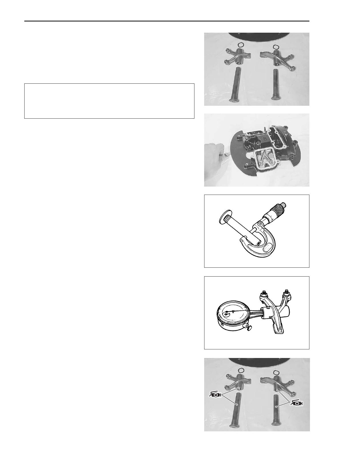
Loosen the rocker arm shafts and pull out the rocker arm shafts.
CYLINDER HEAD COVER DISTORTION
After removing sealant from the fitting surface of the cylinder head
cover, place the cylinder head cover on a surface plate and check
for distortion with a thickness gauge.
"Cylinder head cover distortion
Service Limit: 0.05 mm (0.002 in)
%09900-20803: Thickness gauge
If the distortion exceeds the limit, replace the cylinder head cover.
ROCKER ARM SHAFT O.D.
Measure diameter of rocker arm shaft.
"Rocker arm shaft O. D. (IN & EX)
Standard: 11.966 – 11.984 mm
(0.4711 – 0.4718 in)
%09900-20205: Micrometer (0 – 25 mm)
ROCKER ARM I.D.
When checking the valve rocker arm, the inside diameter of the
valve rocker arm and wear of the camshaft contacting surface
should be checked.
"Rocker arm I.D.
Standard: 12.000 – 12.018 mm
(0.4724 – 0.4731 in)
%09900-20605: Dial calipers
REASSEMBLY
Apply SUZUKI MOLY PASTE to the rocker arms and their shafts.
'99000-25140: SUZUKI MOLY PASTE
(Rocker arm shaft: 27 N.m (2.7 kgf.m, 19.5 lb-ft)
  • Page 1 1
  • Page 2 2
  • Page 3 3
  • Page 4 4
  • Page 5 5
  • Page 6 6
  • Page 7 7
  • Page 8 8
  • Page 9 9
  • Page 10 10

Suzuki VL 800 Owner's manual

Type
Owner's manual

Suzuki VL 800, your new companion on the open road, offers an unparalleled riding experience with its powerful engine and user-friendly features. Embrace the freedom of long journeys with the VL 800's impressive fuel efficiency and reliable performance. Experience the thrill of smooth gear shifting and precise handling, making every ride an adventure. Its sturdy construction ensures durability and dependability, while its classic design exudes timeless style. Discover the joy of riding with Suzuki VL 800!

Ask a question and I''ll find the answer in the document

Finding information in a document is now easier with AI