SystemAir M.HP07 DCI MONO Owner's manual

Type
Owner's manual

This manual is also suitable for

SystemAir M.HP07 DCI MONO is a monobloc backup heater designed for indoor installation to provide hot water and space heating in residential and light commercial applications. It offers 3kW heating capacity and operates on a 220-240V power supply. The unit features automatic air purge and thermal protection for safe and efficient operation. With a compact design and easy installation, it's an ideal solution for providing reliable backup heating.

SystemAir M.HP07 DCI MONO is a monobloc backup heater designed for indoor installation to provide hot water and space heating in residential and light commercial applications. It offers 3kW heating capacity and operates on a 220-240V power supply. The unit features automatic air purge and thermal protection for safe and efficient operation. With a compact design and easy installation, it's an ideal solution for providing reliable backup heating.

MONOBLOC BACKUP HEATER
Electric heater for M.HP0709
INSTALLATION & OWNER’S MANUAL
Thank you very much for purchasing our product,
Before using your unit , please read this manual carefully and keep it for future reference.
7
5
6
8
1 Air purge
2 Backup heater
3 Water IN connection
4 Water OUT connection
5 Thermal protector
6 Circuit breaker
7 Terminal block
8 Terminal block
9 Terminal block
10 Backup heater contactor
9
10
ABOUTTHEDOCUMENTATION................................................................
ABOUTTHEBOX........................................................................................
PREPARATION..............................................................................................
INSTALLATION.............................................................................................
STARTING UP THE SYSTEM......................................................................
MAIN PARAMETERS...................................................................................
1
1
2
3
6
6
1. ABOUTTHEDOCUMENTATION
This document is prepared for authorised installers, read this
document carefully before installation. keep this manual in a handy
place for future reference.
Improper installation or attachment of equipment or accessories
could result in electrical shock, short circuit, leaks, fire or other
damage to the equipment.
All activities described in this manual shall be carried out by a
licensed technician.
Be sure to wear adequate personal protection equipment(protection
gloves, safety glasses) when performing installation, maintenance or
service to the unit.
If unsure of installation procedure or use, always contact your dealer
for advice and information.
The unit described here is designed for indoor installation.
Table 1-1
QUANTITY
INSTALLATION FITTINGS
SHAPENAME
Installation &owner’s
manual(this book) 1
1
M8 expansion screws 3
M4 screws 2
Mounting bracket
1
Mounting bracket
2. ABOUTTHEBOX
2.1 Backup heater
2.1.1 Structure of the backup heater
1Remove the front cover of the backup heater.
3
1
4
2
1
Installation & Owner‘s Manual
CONTENTS PAGE
3. PREPARATION
3.1 Preparing installation site
3.1.1 Installation site requirements of the backup heater
Mind the following spacing installation guidelines:
(unit:mm)
The backup heater is designed to be wall mounted in indoor
locations only.
Make sure the installation surface is a flat and vertical
noncombustible wall.
3.2 Preparing water piping
When installing the backup heater in the system, make sure the
required minimum water flow rate is guaranteed at all times.
For more information, refer to the installation manual of the
outdoor unit.
3.3 Preparing electrical wiring
3.3.1 Overview of electrical connections for external and
internal actuators
>300
>300
>300
>350
>500
Maximum distance between the
backup heater and the external drive
5m If you exceed this
distance, you need an
additional water pump
Operating range (Internal installation) 5~35
More technical specifications of the different connections are
indicated on the inside of the backup heater.
NOTICE
Item Description Wires
Maximum
running
current
Interconnection cable
1 4
Interconnection
cable between
backup heater kit
and outdoor unit
(a)
(a)Minimum cable section: 0.75 mm2;
maximum length: 5 m.
Minimum cable section: 4 mm2;
maximum length: 5 m.
Backup
heater
Power
supply
Required number of
conductors
0.2A
3kW 220-240V 3Wires
75 70 105
280 220 170
140
Ø11
30X11
20
780
630
35
2
Installation & Owner‘s Manual
Keep in mind the guidelines for the measures:
4 INSTALLATION
4.1 Opening the units
4.1.1 To open the backup heater
1
2
3×
4.2
Mounting the backup heater
4.2.1 To install the backup heater
1Fix the wall bracket to the wall with M8 screws. 2Fix the wall bracket to the backup heater with M4 screws.
Mark the position of the hole at the bottom of the backup
heater.
Drill a hole for the bottom screw and insert a plug.
3
Installation & Owner‘s Manual
2
3
1
NOTICE
3Hang the backup heater onto the wall bracket. Make sure it
is fixed properly.
4Fix the bottom of the backup heater to the wall with an M8
expansion screws
.
4.3
Connecting the water piping
4.3.1 To connect the water piping
1Connect the water piping (field supply) to the water in and
outlet of the backup heater.
3Water inlet
4Water outlet
3 4
Do NOT use excessive force when connecting the piping.
Deformation of the piping can cause malfunctioning of the unit.
NOTICE
INFORMATION
4.4 Connecting the electrical wiring
4.4.1 To connect the electrical wiring on the backup heater
Routing Possible cables
(depends on the installed options)
a
Low voltage
Backup heater kit sensor
(interconnection with outdoor unit)
b
High voltage
Backup heater kit connection
(to outdoor unit)
Main power supply
CAUTION
The function of the 3-way valve is to switch the water pipe.
When we use the heat mode or hot water mode,the water flows
AB to A; when we use the cool mode,the water flows AB to B.
When the outdoor unit is in cool mode, condensation may
occur. Therefore provide a bypass by installing a valve kit to
the water inlet of the backup heater. For instructions, refer to
the installer reference guide. Do NOT install any other valve kit
than the one specified in the installer reference guide.
Inside the backup heater, an automatic air purge valve
isinstalled. During operation
make sure the automatic air purge
valve is open(at least 2 circles),remove air in the circuit as much
as possible, air present in the water circuit migth cause
malfunctioning of the backup heater.
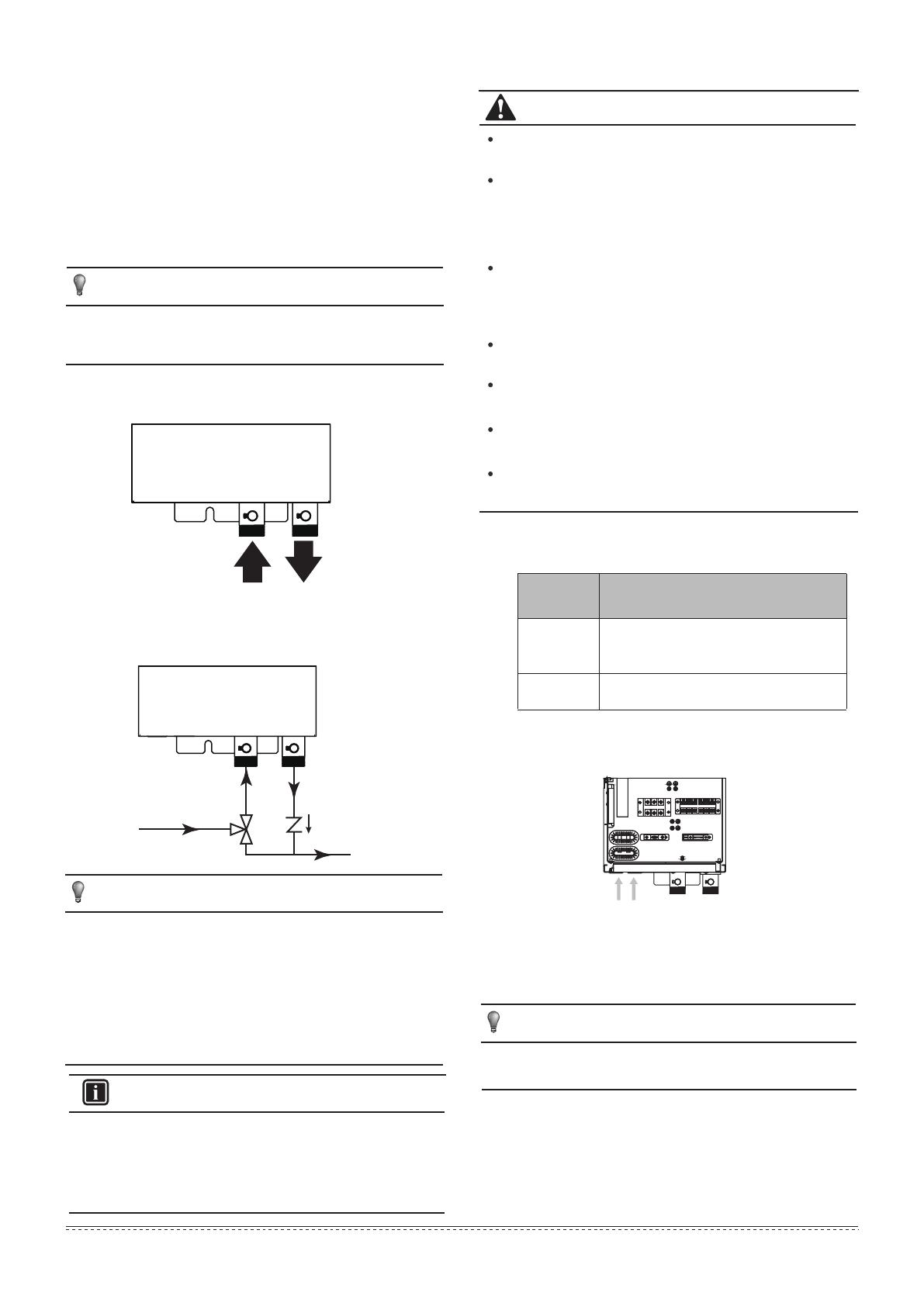
1Insert the wiring from the bottom of the backup heater.
2Inside the backup heater, route the wiring as follows:
b Low voltage wiring
a High voltage wiring
3Fix the wiring with cable ties to the cable tie mountings.
NOTICE
The distance between the high voltage and low voltage cables
should be at least 25 mm.
a b
A
B
AB
4
Installation & Owner‘s Manual
Set the electric leakage protector electric technical standards
of the state.
The power cord and the signal cord and properly without mutual
interference connection pipe or valve
After wire connection, check it again correctness before
poweron.
If you want to rotate the electric box, please release the iron tie
on the top of the E-box to avoid sensor's connection loosing.
The power supply should be an independent circuit with rated
voltage.
Power supply circuit should be earthed effectively.
The wiring must be performed by professional technicians in
accordance with national wiring regulations and this circuit
diagram.
An all-pole disconnection device which has at least 3mm
separation distance in all pole and a residual current
device(RCD)with the rating of above 10mA shall be
incorporated in the fixed wiring according to the national rule.
L N
L N
XT5
Power Supply Wires
4.4.2 To connect the backup heater power supply
CAUTION
WARNING
4.4.3 To connect the backup heater kit to the outdoor unit
Fix the cable with cable ties to the cable tie mountings.
INFORMATION
For details about the connections, refer to the wiring diagram.
Use a multicore cable.
If a tank with a builtin electrical booster heater is part of the
system, use a dedicated power circuit for the backup heater and
booster heater.
NEVER use a power circuit shared by another appliance. This
power circuit must be protected with the required safety devices
according to the applicable legislation.
To guarantee the unit is completely earthed, always connect the
backup heater power supply and the earth cable.
For the sensor, connect 2 wires between backup heater terminals XT20M/5+6 and control box connector T1.
For the connection with the control box, connect 3 wires between backup heater terminals XT20/1+2 and control box terminals XT9/31+39.
For the power supply, connect 3 wires to XT5/L+N+
123456
XT9
XT20 31(H1)
39(N)
indoor unit outdoor unit
5
Installation & Owner‘s Manual
6.2 Water pressure drop
6.1 Main parameters
5 STARTING UP THE SYSTEM
6 MAIN PARAMETERS
For instructions on how to configure and commission the
system, and hand it over to the user, refer to the installation
manual of the outdoor unit.
6
Installation & Owner‘s Manual
0.0
1.0
2.0
3.0
4.0
5.0
6.0
7.0
8.0
0.0 0.2 0.4 0.6 0.8 1.0 1.2 1.4 1.6
Water Drop [kPa]
Flow rate [m
3
/h]
0709 Eheater
3.0kW
13A
220-240V~ 50Hz
Dimensions Unit 780mm×220mm×280mm
Packed unit 890mm×325mm×385mm
Weight Unit 18.5kg
Packed unit 24kg
5~35
Pipe diameter Water inlet/outlet G1"
Power supply
Model
main parameters
Operation range
Capacity
Rated current
MD16IU-014BW
16110600000085
  • Page 1 1
  • Page 2 2
  • Page 3 3
  • Page 4 4
  • Page 5 5
  • Page 6 6
  • Page 7 7
  • Page 8 8
  • Page 9 9

SystemAir M.HP07 DCI MONO Owner's manual

Type
Owner's manual
This manual is also suitable for

SystemAir M.HP07 DCI MONO is a monobloc backup heater designed for indoor installation to provide hot water and space heating in residential and light commercial applications. It offers 3kW heating capacity and operates on a 220-240V power supply. The unit features automatic air purge and thermal protection for safe and efficient operation. With a compact design and easy installation, it's an ideal solution for providing reliable backup heating.

Ask a question and I''ll find the answer in the document

Finding information in a document is now easier with AI