Superabrasive UserManual OriginalLanguageLavina®30L‐S‐E 9/2014
LAVINA® 30L-S-E User Manual
www.superabrasive.com / factory@superabrasive.com

Superabrasive UserManual OriginalLanguageLavina®30L‐S‐E 9/2014
2
1.GENERALINFORMATION 3
Manufacturer 3
GeneralDescription 3
MachineCharacteristics 3
MainDesign 3
EnvironmentalConditions 3
ElectricalConnection 3
VacuumConnection 4
TechnicalData 4
Ce‐certification4
Vibrations4
SonorousEmissions 4
LabelData4
CustomerService 4
2.SAFETYINSTRUCTIONS 4
RecommendedUse 4
ProhibitedUse 4
PreparationforWork 4
ProtectionDevices 5
ArrestFunctions 5
SafeUse5
ResidualRisks 5
BeforeYouBegin 5
OperatingMachine 5
AfterWorkisCompleted 5
TheWorkArea 5
PersonalProtectiveEquipment(Ppe) 5
Operator5
3.HANDLINGANDTRANSPORTATION6
PreparingtheMachineforTransportation 6
LifttheMachinefromWorkingtoToolMounting
Position6
Lifting6
AdjustingtheHandle 6
Storage7
MountingOfGuardAssembly7
4.OPERATION 7
PreliminaryControls 7
WaterFlowControlUnit 7
AdjustingandMountingTools 7
FrameBlocking(U‐Joint) 8
ControlBoard 8
StartingtheMachine 8
OperatingtheMachine 8
StoppingtheMachine 8
Alarm8
5.TOOLSANDACCESSORIES 9
Weights9
ToolHolderKey 9
FoamPlate9
SecurityPlateforQuickchangePads 9
6.POPULARTOOLS 10
7.EXPLODEDVIEW 11
GeneralExplodedView(Fig.7.1) 11
TopCoverExplodedView1(Fig.7.2) 11
PlanetaryDriveExplodedView(Fig.7.3) 11
TopCoverExplodedView2(Fig.7.4) 11
BottomCoverExplodedView1(Fig.7.5) 12
BottomCoverExplodedView2(Fig.7.6) 12
PulleyUnitsExplodedView(Fig.7.7) 12
CarriageExplodedView(Fig.7.8) 12
ToolHolderExplodedView(Fig.7.9) 12
8.MAINTENANCEANDINSPECTION 13
Cleaning13
CheckDaily 13
Checkandreplaceafterthefirst15WorkingHours 13
CheckEvery200WorkingHours 13
CheckEvery400WorkingHours 13
Vacuum13
WaterLeaks 13
MechanicalParts 13
ElectricalSystem 13
ElectricalSchemes 14
9.TROUBLESHOOTING 15
IndexofProblemsandSolutions
9.1ReplacingPowerCordandPlugs 15
9.2DismountingandMountingToolHoldertochangebuffers
andspiders,changingV‐RingsandFelt‐Rings15
9.3TensioningandReplacethePlanetaryBelt 16
9.4TensioningUsedPlanetaryBelt 16
9.5MountingandTensioninganewPlanetaryBelt 16
9.6CheckingtheTensionoftheBelt 17
9.7ReplacingofthePulleyUnits 18
9.8MountingtheBelt 19
9.9MotorConnection 19
9.10FaultDiagnosisInverterYASKAWAV1000 20
10.WARRANTYANDRETURNS
Warranty23
ReturnPolicy 23
11.DISPOSAL 23
12.MANUFACTURER’SCONTACTS 23
13.SPAREPARTS 24
AssemblyAndPartsSpecifications 24
13.1GeneralParts/formachinesproduced
beforeJan.12014/ 24
13.1GeneralParts/formachinesproduced
afterJan.12014/ 24
13.2TopCoverParts1/formachinesproduced
beforeJan.12014/ 25
13.2TopCoverParts1/formachinesproduced
afterJan.12014/ 25
13.3TopCoverParts2 26
13.4PlanetaryDriveParts 26
13.5BottomCoverParts1 26
13.6BottomCoverParts2 27
13.7PulleyUnitsParts 27
13.7a.PulleyUnitAssembly 28
13.7b.DrivingPulleyUnit 28
13.8ToolHolderParts 28
13.9WaterSupplyParts/formachinesproduced
beforeJan.12014/ 28
13.9WaterSupplyParts/formachinesproduced
afterJan.12014/ 28
13.10CarriageParts/formachinesproduced
beforeJan.12014/ 29
13.10CarriageParts/formachinesproduced
afterJan.12014/ 30
13.11ControlBoxParts380Volt 31

Superabrasive UserManual OriginalLanguageLavina®30L‐S‐E 9/2014
3
1.GENERALINFORMATION
Thisowner’smanualisintendedfortheoperatoroftheLavina®Smachine,theservicingtechnicianaswellasforanyoneinvolvedwith
operatingorservicingthemachine.Werecommendthatyoureadtheinstructionsverycarefullyandfollowthemstrictly.Themanual
includesinformationaboutassembling,using,handling,adjustingandmaintainingyourLavina®Sfloorgrindingandpolishingmachine.
MANUFACTURER
Superabrasivewasfoundedin1987,asamanufacturerofhighqualitydiamondtoolsforthestoneandconcreteindustry.Today,
Superabrasiveisoneoftheworld’sleadingcompaniesintheproductionofdiamondtoolsandfloorgrindingmachinery.At
Superabrasive,westrivetodelivertheverybestsolutionstoourcustomers,andenablethemtoworkmoreefficiently.
GENERALDESCRIPTION
TheLavina®Smachineisintendedforgrinding,polishingandbuffingconcrete,marble,granite,limestone,andterrazzosurfaces
withdiamondtools.
TheLavina®Smachineisathree‐discmachine,whichcanbeuseddryaswellaswet.
Forbestresults,useonlytoolsmanufacturedorrecommendedbySuperabrasiveanditsdistributors.Additionally,themachinecould
beusedforgrindingwoodfloorsurfaces.
TheLavina®Smachineismanufacturedandfittedfortheabove‐mentionedapplicationsonly!Everyotheruse
maypossessriskstothepersonsinvolved.
MACHINECHARACTERISTICS
TheLavina®Smachineismadeoftwomaincomponentsections:
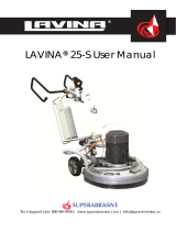
MAINDESIGN
Thetwomaincomponentsarethecarriageandmainhead.
Thehandle(Fig.1.1)ontheframeisadjustableinheightandallowstheoperatortoworkina
correctandsafeworkingposture.
Thehalogenspotlight(Fig.1.2)enablestheoperatortoworkindarkerareas.
Existinglightingsystemdoesnotreplaceadequateoverheadlighting.
Aframe(U‐jointtechnology)ontopofthemotorbaseallowsthemainheadtomovetoall
sidesanditgivesmoregrindingcapacity.
Thecontrolsarepositionedontopoftheelectricalbox(fig.1.3)
Theelectricalbox(fig.1.3)containstheelectricswitchingdevicesandtheinverter.
Themainfeedingcableisconnectedwithaplugandsocketontop.Themotorfeedingcable
ispluggedintothesocketlocatedonthebottomofthebox.
Thetankisontheoppositesideoftheframe,sothattheweightofthe
waterhasnoinfluenceontheoperationofthemachine.Theframeweight,ontheotherhand,
isfullyabsorbedbythedrivingwheels.Anelectricpumpspraysthewaterthroughafront
sprayerorinternal.
Themotorismountedonthebaseplateandisdrivingthethreeheadswithabeltsystem.
Theplanetaryheadisdrivenbyasecondflatbelt.
ENVIRONMENTALCONDITIONS
ThetemperaturerangeforoperatingtheLavina®Smachineoutdoorsisbetween41°Fand
86°For5°Cand30°C.NeverusetheLavina®Smachineduringrainorsnowwhenworking
outdoors.Whenworkingindoors,alwaysoperatethemachineinwell‐ventilatedareas.
ELECTRICALCONNECTION
Thevoltage(Volt)andpower(Ampere)aredisplayedonalabelontheelectricalcontrolboxto
avoidanyincorrectconnection.Refertothesebeforeconnectingthepower.Toavoid
electricalshocks,makesurethegroundpowersupplyisfunctioningproperly.
Figure 1.1
Figure 1.3
Figure 1.2

Superabrasive UserManual OriginalLanguageLavina®30L‐S‐E 9/2014
4
VACUUMCONNECTION
Aconnectionforavacuumdustextractorislocatedonthecarriage.TheLavina®Smachinedoesnotincludeavacuumdustextractor.
Thecustomermustpurchasethevacuumdustextractorseparately.ThehoseofthevacuumextractormustbeØ50mmandcanbe
glidedoverthepipe.Thevacuumdustextractormustbeadaptedforfloorgrindersandhaveaminimumairdisplacementof320m3/h
withanegativevacuumof21kPa.
TECHNICALDATA
CE‐CERTIFICATION
TheLavina®S‐Emachineisdesignedtooperatecorrectlyinan
electromagneticatmosphereofindustrialtypeandisequippedwithall
themechanicalandelectricalsafetyprotectionsinconformitywiththe
followingEuropeanCEErulesandregulations:
TheLavina®S‐EmachinecomplieswiththeSafetyDirectiveformachines
2006/42/EC,theEMCDirective2004/108/ECandtheLowVoltage
Directive2006/95/EC.
AlsocomplieswiththenormsinuseBDSENISO12100,BDSEN13862,BDS
ENISO13857,BDSEN349,BDSENISO13850,BDSEN13732‐1,BDSEN
953,BDSENISO13849‐1,BDSEN1037,BDSENISO5349‐1,BDSENISO
11201,BDSENISO3744,BDSEN1033:2002,BDSEN60204‐1,BDSEN
1837,BDSEN61000‐6‐4,BDSEN61000‐6‐2,BDSEN61000‐4‐2,BDSEN
61000‐4‐4,BDSEN61000‐4‐5,BDSEN61000‐4‐11,BDSEN55016‐2‐1
Testresultsareapartofthemachine’stechnicalinformationandcanbe
sentuponaspecialrequest.ThemachineisdeliveredwiththeCEmark
exposedandprovidedwithaECdeclarationofconformity.
VIBRATIONS
Themeasuredvibrationvalueonthesurfaceofgrippingincaseofguidingthemachineisahw=1,25m/s2.Themeasurementismadein
accordancewiththeBDSENISO1033andBDSENISO5349‐1.
SONOROUSEMISSIONS
Themaximumnoiselevelatdistanceofthemachineof1mincaseofworkingatidledoesnotexceed70dB(A).Themeasurementismadein
accordancewiththeBDSENISO11201andBDSENISO3744.
LABELDATA
ThedataonthelabelprovidesthecorrectVoltageandkW(neededforoperationalpurposes);
Weight(neededfortransportationpurposes);productionyearandserialnumber(neededformaintenancepurposes).
CUSTOMERSERVICE
ForcustomerassistanceandtechnicalsupportcontactyourlocaldistributororcontacttheproducerSuperabrasiveLtd.orvisitusat
www.superabrasive.com,whereyoucandownloadacopyofthismanual.
2.SAFETYINSTRUCTIONS
RECOMMENDEDUSE
TheLavina®Smachineisdesignedandmanufacturedto
grindandpolishconcrete,terrazzo,andnaturalstonefloors.
Itcanbeusedforrenovationaswellasforpolishing.The
machineisdesignedfordryorwetuse.Whenusingitdry,
useavacuumofappropriatesize.Formoreinformation,
pleaserefertothechapteronhandlingthevacuum
connection.
PROHIBITEDUSE
ThemachineMUSTNOTbeused:
Forapplicationsdifferentfromtheonesstatedinthe
generaldescriptionchapter.
Fornon‐suitablematerials.Inenvironmentswhich:
- Possessrisksofexplosion,
- Possesshighconcentrationofpowdersoroilsubstances
intheair,
- PossessrisksoffireFeatureinclementconditions,
- Possesselectromagneticradiation.
PREPARATIONFORWORK
Makesurethat:
Youhaveclosedtheworkarea,sothatnounfamiliarwith
operatingthemachinecanenterthearea.
Thetoolplateandtoolsareadjustedtothemachine
properly.
Therearenomissingpartsofthemachine
Themachineisinuprightworkingposition.
Theprotectiondevicesareworkingproperly.
Theelectricalcableisfreetomoveandfollowthe
machineeasily.
Lavina®30L‐S‐E
Voltage/Hz3phx380V50‐60Hz
AmperageMax30Amps
Power11kW15HP
Toolholderrpm300‐1100rpm
Workingwidth765mm 30.1”
Tooldiameter(QCPlate)3x335mm 3x13.2”
Weight301kg 664lbs
Grindingpressure181kg 399lbs
Additionalweightmax2x29kgmax2x64lbs
Applicationwetanddry
VacuumhoseportYes
Watertankcapacity20l5.2gal
Waterfeedwithpump(peripheralandfront)
Cablelength17.4m57ft
MachineLxWxH1880x805x1180mm76x32x46.5”
PackingLxWxHonskid1150x730x1530mm45.3x28.7x60.2”
PackingLxWxHCrate11150x730x1100mm45.3x28.7x43.3”
+Crate21150x730x900mm45.5x28.7x35.4”

Superabrasive UserManual OriginalLanguageLavina®30L‐S‐E 9/2014
5
Inordertokeeptheelectricalcablefrombeing
damaged,novehicleshouldcrossthezonewhere
electricalcablesaresituated.
PROTECTIONDEVICES
Themachineisequippedwithseveralprotectiondevices
includingthefollowing:
Anemergencystopbutton
Aprotectionskirtandahoodforprotectingthetool
plates.
Thesedevicesprotecttheoperatorand/orotherspersons
frompotentialinjuries.Donotremovethem.Beforeusing
themachine,pleaseensurethatallprotectiondevicesare
mountedandfunctionproperly.TheSecurityplate
preventstheQuickChangepadstofromlooseningduring
work
ARRESTFUNCTIONS
Functionsofarrestingofthemachinearefollowing:
Buttontostopthemotor(category1)
Emergencybutton(category1)
SAFEUSE
TheLavina®Sisdesignedtoeliminateallriskscorrelated
withitsuse.However,itisnotpossibletoeliminatetherisks
ofaneventualaccidentwiththemachine.Unskilledor
uninstructedoperatormaycausecorrelatedresidualrisks.
Suchrisksare:
PositionRisks:duetooperator’sincorrectworking
position
TanglingupRisks:duetowearinginappropriateworking
clothes
TrainingRisks:duetolackofoperationaltraining.
NOTE::Inordertoreduceallconsequencesoftheabove‐
mentionedrisks,weadvisethatmachineoperatorswill
followtheinstructionsinthemanualatalltimes.
RESIDUALRISKS
Duringthenormaloperatingandmaintenancecycles,the
operatorisexposedtofewresidualrisks,whichcannotbe
eliminatedduetothenatureoftheoperations.
BEFOREYOUBEGIN
Workingareamustbeclearfromanydebrisorobjects.
Afirst‐timeoperatormustalwaysreadthemanualand
payattentiontoallsafetyinstructions.
Allelectricconnectionsandcablesmustbeinspectedfor
potentialdamages.
Groundwiresystemofthepowersupplymustbealso
inspected.
Performgeneraldailyinspectionsofthemachineand
inspectthemachinebeforeeachuse.
Alwaysinspectthesafetydevices:MounttheSecurity
platefortheQuickChangepads.
Theemergencybreakmustbeclearandworking
Thetoolprotectormustbeworking
Themachinemustbeclean
Neveroperatethemachineintherain!
Confirmthattherearenomissingpartsespeciallyafter
transportation,
repairormaintenance.
Beforefillingthewatertankwithwatermake
surethemachineisnotworkingandthemain
switchisturnedoff.
Beforeturningonthemachinemakesurethatthebaseis
placedonthefloor,themachineMUSTNOTbeinan
uprightpositionwhenturnedon!
OPERATINGMACHINE
WhenoperatingtheLavina®S,makecertainthatthereis
noone,butyouaroundthemachine.
Neverleavethemachineunattendedwhileworking.
Theelectricalcablemustmovefreelyandmustbe
damage‐free.
Thewaterhosemustmovefreelyandmustbedamage‐
free.Checktomakesurethefloor,youarepreparingto
workon,iseven.Ifthefloorisuneven,itmaydamagethe
machine.
AfterWorkiscompleted
Cleanthemachineanditssurroundingsproperly
Emptyandcleanthewatertank
Unplugthemachineandwinduptheelectricalcable
Storethemachineinasafeplace
THEWORKAREA
Makecertainthatpeopleorvehiclesdonotenterthework
area.
Avoidcablesandhosesbeingintheway.
Alwayscheckthefloorfordebris
PERSONALPROTECTIVE
EQUIPMENT(PPE)
Alwayswearsafetyshoeswhenworkingwiththe
machine.
Alwayswearearprotectorswhenworkingwiththe
machine.
Allpersonnelintheimmediateworkareamustwear
safetyglasseswithsideshields.
Alwayswearsafetygloveswhenchangingthetools.
Alwayswearclothessuitableforthework
environment.
OPERATOR
TheLavina®Smachine.
Theoperatormustknowthemachine’swork
environment.Onlyoneoperatoratatimecanwork
withthemachine.Theoperatormustbeproperly
trainedandwellinstructedprioroperatingthe
machine.
Theoperatormustunderstandalltheinstructionsinthis
manual.
Theoperatormustunderstandandinterpretallthe
drawingsanddesignsinmanual.
Theoperatormustknowallsanitationandsafety
regulationspertainingtotheoperationof
Theoperatormusthavefloorgrindingexperience.
Theoperatormustknowwhattodoincaseof
emergency.
Theoperatormusthaveanadequatetechnicalknowledge

Superabrasive UserManual OriginalLanguageLavina®30L‐S‐E 9/2014
6
3.HANDLINGANDTRANSPORTATION
PREPARINGTHEMACHINEFORTRANSPORTATION
Unplugthemotorcableplugfromthecontrolboxanddisconnectthewaterhosefromthemainheadbypullingitout
(Fig.3.1)(Fig.3.2).Windtheelectricalcableonthecarriage.Releasethepinsetswhichattachtheheadtothecarriage.Pull
outthevacuumhoses(Fig.3.3),anddismounttheheadfromthecarriage.
TheheadoftheLAVINA®Smachinehasonebarforsupportandisusedashandlesforeasymovingandtransportation.
LIFTTHEMACHINEFROMWORKINGTOTOOL
MOUNTING
POSITION
Pushthefronthandledownandswivelittothe
front(Fig.3.4).Pullthehandleupandensurethe
headisastableuprightposition,for
mounting/dismountingthetool.Ensurethatthe
watertankisemptybeforeflippingthemachine.
Pulltheheadinuprightposition(Fig.3.5).The
machinesmanufacturedafterJan.12014are
withchangedlockingofthefronthandleas
shownonthefig.3.4.1.
LIFTING
Liftingthemachinebycraneispossiblewiththeeyebolt,whichismountedonthecarriage(seeFig.
3.6).Theeyeboltandmachineconstructionisratedonlyfortheweightofthemachine.Donotlistany
otherleadsonthemachine.Alwaysusehoistingequipmentratedfor300kgor660lbs.
ADJUSTINGTHEHANDLE
TheHandleontheframe
isadjustableinheightand
allowstheoperatorto
workinacorrectandsafe
posture.Themachines
manufacturedafterJan.1
2014arewithchanged
lockingofthehandleon
theframe.Theunlocking
isbypullingthehandle
Figure 3.1 Figure 3.2 Figure 3.3
Figure 3.6
Figure 3.5
Figure 3.4 Figure 3.4.1
Figure 3.7 Figure 3.7.1 Figure 3.7.2 Figure 3.8

Superabrasive UserManual OriginalLanguageLavina®30L‐S‐E 9/2014
7
(fig.3.4.1)Thelockingisautomaticallyunderactionofthespring.Fig.3.7.2showsallpossiblepositionofthehandle.Choose
theuprightpositiontomoveeasythemachine.
STORAGE
AlwaysstoreandtransporttheLavina®S
machineinadryplace.Nevertransportthe
Lavina®Smachineunprotected;itmaybe
damagediftransportedunprotectedduring
rainorsnow.
Whenstoringthemachinethetemperature
mayfalldowntoortolessthan32F(or0oC)youshouldemptythewaterfromthesystemusingthefollowingsteps:
‐Pulloutthehoseofthetank(Fig.3.9)
‐Usingcompressedairblowoutthewaterfromthesystemforthetwopositionsoftheturn‐cock(Fig.3.10,Fig.3.11).
MOUNTING OF GUARD ASSEMBLY
SetthemachineinthepositionshownonFig3.12,turntheGuardAssembly(Fig3.13).PullbackwardstheGuardAssembly,you
havetobesurethattheToolholdershavepassedthroughit(Fig3.14).PuttheGuardAssemblyonposition(Fig3.15).
Dismountingmustbedoneinreversesequence.
4.OPERATION
PRELIMINARY CONTROLS
Inspecttheworkingareaasexplainedinthesafetyinstructions.Forwetuse,fillthewatertankwhentheelectricalcableis
disconnected.Connectthevacuumextractorandensurethatthevacuumhoseisclearandthatitwilleasilyfollowthemachine.
PluginthemachineandmakesurethatthepowercordisfreetofollowthedirectionoftheworkingLavina®Smachine.
WATER FLOW CONTROL UNIT
Theoperatorcanchoosethewatersprayerinthefrontwhenthetapisinthehorizontalposition(Fig.4.1),thewater
willsprayunderthecoverofthemachine
whenthelevelisintheverticalposition
(Fig.4.2).Theflowregulatingvalve
locatedonthetank(Fig.4.2.1)is
increasingorreducingthewaterflowto
the
working
area–infrontofthe
machineorunderthemainheadcoverof
the
machine
/onlyformachinesproduced
afterJan.12014/
.
ADJUSTING AND MOUNTING TOOLS
Mountthetoolsonlyafterensuringthatthereisenoughdiamond
bondmaterialleft.Besurethattheplatesarealwayscleanbefore
mounting.WARNING:Alwayssecurethe“QuickChange”padswith
thesecurityplate(Fig.4.3),lockwiththetoolholderkey(Fig.5.3).
DiamondtoolswithVelcroareattachedtothree13,2inchfoam
F
g
ure 3.13 F
g
ure 3.14
F
g
ure 3.12 F
g
ure 3.15
Figure 3.9 Figure 3.10 Figure 3.11
Figure 4.2.1
Figure 4.1 Figure 4.2
Figure 4.4
Fi
g
ure 4.3

Superabrasive UserManual OriginalLanguageLavina®30L‐S‐E 9/2014
8
plates(Fig.4.4).Thefoamplatesaremountedonthekeylock(butterfly).Alwaysusethetoolholderkey(Fig.5.3).
FRAME BLOCKING (U-JOINT]
Therelationbetweentheworkingheadandthetrolleyistheframe(U‐joint),whichallowsrotation
abouttwoperpendicularaxestobetterfollowtheprofileofthefloor.
Themovementalongtheoneaxiscanbefixedwithtwoscrews(Fig.4.5)andthatblockthelateral
movementofthemachine.
THE CONTROL BOARD
1. Powercableplug
2. DigitalRPMindicatorIndicatestherevolutionperminuteofthegrindingplates(nottherevolutionperminuteoftheentire
unit).
3. Polishing/GrindingswitchIn“grinding”position,theoperatorhasthepossibilitytocontroltherpmfrom300until
maximum700rpm.In“Polishing”positionfrom300‐1100rpmmaximum.
4. Lampcablegland
5. InverteralarmledLightsbluewhentheinvertergoesintoalarmmode.
6. WaterpumpswitchLightsorangewhenthewaterpumpisworking.
7. Powerledlightsgreenwhenthepowerison
8. Forward/Reverseswitchchooseforwardforclockwiserotationof
thegrindingplatesorreverseforanti‐clockwiserotationofthe
grindingplates
9. PotentiometerchangestheRPMofthegrindingplatesfrom300‐
1100rpm
10. Resetbuttonresetsthealarmoftheinverter
11. OFFbuttonstopsthemotor
12. ONbuttonstartsthemotor
13. EmergencybuttonusedinEmergencysituationsforstoppingthe
motor
STARTINGTHEMACHINE
First,followthedirectionsinchapterSafetyDevicesandSafetyInstructions.
Next,pulltheemergencystop(13)toensurethatthemachineisinworking
condition.Checkthepotentiometer(9)andensurethatitissetatthe
workingspeed.Ifworkingwet,addwatertothefloorsurface.Ifworking
dry,omitthisstep,andinstead,switchonthevacuumunit.Finally,holdthe
machinefirmlyandpushthestartbutton(12).
OPERATINGTHEMACHINE
Guidethemachineinstraightlinesacrossthefloor,andwitheachnewlineoverlapalittlebitofthepreviouslycompletedsurface.
Workataconstantspeedallowingthetoolstimetoworkataspeedappropriateforthetools’gritsize.Avoidvibrations.Donotstop
theLavina®Smachineinonespotwhilethetoolsarestillworkingbecausetheywillleavemarksonthefloorsurface.Whenworking
wet,preliminarychosewiththewatertap(Fig4.1b)thepositionforwaterfeedandperiodicallystartthepumptoreleasewateronto
thefloorsurface(Fig.4.6Pos.6).Whenworkingdry,checkthefloorsurfaceperiodicallytoensurethatdustisnotaccumulatingonthe
surface,alsocheckregularlyifyourvacuumworksproperly.
STOPPINGTHEMACHINE
Thestoppingofthemachinemustbedonegraduallyuntilthemotorstops.Donotstopmovingthemachinebeforearrestingthe
motorasthetoolscoulddamagethesurface.Tostoppushtheoffbutton(11).UsetheEmergencybutton(13)onlyinemergencyor
useittoswitchthepowertotallyoff.Remembernottoholdthemachineinonespotbeforeturningoffthemotor.
ALARM
TheAlarmlight(5)willlightincaseinvertergoesinalarmmode.Themostcommonfailureismotorinoverload.Toresetthemode
pushresetbutton(10).
12345678
910111213
Fgure 4.6
Fgure 4.5

Superabrasive UserManual OriginalLanguageLavina®30L‐S‐E 9/2014
9
5.TOOLSANDACCESSORIES
WEIGHTS
Superabrasiveoffersadditionalweightsforincreasingtheproductivityofthemachine(Fig.5.1).Each
additionalweightweighsabout64lbsor29kg.Eachindividualapplication,typeandconditionof
surface,powercapacityoftheoutlet,etc.willdeterminethenumberofweightsyoucanusewithout
trippingabreaker.Theweightstacksontothreepoststhatarearoundtheouterbowl(Fig.5.2).The
additionalweightsdependonthetools;itisnotalwayspossibletoassweights.Sometoolsworktoo
aggressivelyandthemachinecanstop.TheweightcanbeorderedwithitemnumberA08.00.00.00
TOOLHOLDERKEY
Thetoolholderkey(Fig.5.3)isusedforadjusting,mountinganddismountingofthefoamplates.
Alwaysusethekeyformounting.
ItemnumberisA03.00.00.00
FOAMPLATE
DiamondtoolswithVelcroaremountedonthefoamplate9“(Fig.5.4).Thefoamplateismounted
onthe“QuickChange”System.
ItemnumberisLV‐13,5‐FP‐S
SECURITYPLATEFORQUICKCHANGEPADS
Plate(Fig.5.5)usedtoensurethe“Quickchange”pads.
ItemnumberisA38.00.02
Figure 5.3
Figure 5.1
Figure 5.4
Figure 5.2
Figure 5.5

Superabrasive UserManual OriginalLanguageLavina®30L‐S‐E 9/2014
10
6.POPULARTOOLS
RECOMMENDEDTOOLS
QuickChange System and Tooling feature extremely fast and convenient tool changes, and a
long tool
life, providing for great long‐term cost savings. The QuickChange pads are produced in
four different
bonds for super hard, hard, medium and soft concrete, in a variety of grit sizes.
They are offered with
1 or 2 buttons or rectangular segments, which allows you to customize the aggressiveness of the
cut.
Calibra grinding discs: our popular ceramic bond discs are designed for the removal of difficult
scratches
and they save you valuable time by eliminating the need for multiple passes with metal
tools. They can be
used wet or dry, and are best for hard concrete applications.
They are 3-inch, with included Velcro back attachment.
NATO® polishing discs feature a special resin formula designed for both wet and dry applications and a unique
design with
wide channels allowing for work on a cleaner surface and ensuring a quality polish. Available in 3 and 4 in
sizes. They are with
included Velcro attachment.
V‐HARR® Premium Polishing Pads are designed for mechanically polishing and restoring concrete; also ideal for
terrazzo and
hard stone floors. V‐HARR® pads are offered in a wide variety of diameters and grit sizes to
accommodate many applications.
Dry use is strongly recommended.
Shine Pro® are high quality diamond‐impregnated pads for floor maintenance. Available in a variety of sizes, and are
great for
daily use. When used wet, they require only water (no wax or chemicals needed) and are a very environmentally
friendly solution
for maintaining floors.
UseonlySuperabrasive’srecommendedtools.Formoretoolingoptions,visitwww.superabrasive.com

Superabrasive UserManual OriginalLanguageLavina®30L‐S‐E 9/2014
11
7.EXPLODEDVIEW
GENERALEXPLODEDVIEW(FIG.7.1)
TOPCOVEREXPLODEDVIEW1(FIG.7.2)
PLANETARYDRIVEEXPLODEDVIEW(FIG.7.3)
TOPCOVEREXPLODEDVIEW2(FIG.7.4)
Figure 7.3 Figure 7.4
Figure 7.2
Figure 7.1

Superabrasive UserManual OriginalLanguageLavina®30L‐S‐E 9/2014
12
BOTTOMCOVEREXPLODEDVIEW1(FIG.7.5)
BOTTOMCOVEREXPLODEDVIEW2(FIG.7.6)
PULLEYUNITSEXPLODEDVIEW(FIG.7.7)
CARRIAGEEXPLODEDVIEW(FIG.7.8)
TOOLHOLDEREXPLODEDVIEW(FIG.7.9)
Figure 7.8
Figure 7.7
Figure 7.5 Figure 7.6
Figure7 .9

Superabrasive UserManual OriginalLanguageLavina®30L‐S‐E 9/2014
13
8.MAINTENANCEANDINSPECTION
CLEANING
Keepyourmachineclean.Cleaningthemachineonaregularbasiswillhelpdetectandsolvepotentialproblemsbeforetheycancause
damagetothemachine.Mostimportantly,checkandcleanthetoolplateconnections,powercords,plugs,vacuumhoses,andwater
tank.
CHECKDAILY
AfteroperatingtheLavina®Smachine,theoperatorshouldconductavisualinspectionofthe
machine.Anydefectshouldbesolvedimmediately.Patattentiontopowercords,plugs,vacuum
hoses,looseboltsand/orscrews.
Toolholders:Buffersandspidersareconsumablesandmustbevisuallyinspectedonadailybasisand
replacedifneeded.Makesureflangesordiscsareproperlymountedandlockedsecurelyinplace.The
keylockholders(butterflies)shouldalsobechecked.
Checktherubberbuffersandmakesuretheholdersaresecure.Theflangeholdingthebuffers(Fig.8.1‐
1)hastobefirmlysecuredtotheunit.Ifthereisagapseenhere,thatmeansthatthereareloose
screwssecuringtheholder.Thescrewshavetobetightenedimmediatelytosafelyoperatethe
machine.Workingwithloosescrewcouldcausebaddamagetothemachine.Thetighteningforceof
thescrewshastobe25‐30N.m(18‐22ft/lbs).
Itisveryimportanttoregularlycheckthescrews(Fig.8.1‐2)thatfixthe“QuickChange”holdertothe
safetypart,sothattheholderwillnotflyawayifthebuffersgetdamaged.“QuickChange”shouldalso
beclean.Thetensionoftheplanetarybeltcanbecheckeddailybymovingthemainheadandfeeling
theresistanceofthemovingpulleys,ifthebeltslipstension,immediatelysee:TROUBLESHOOTING.
CHECKANDREPLACEAFTERTHEFIRST15WORKINGHOURS
Checkthebelttensionafter15hoursworkingwiththemachine.
Thebottomcoverhasacontrolcover(Fig.8.2)thatallowsfastandeasycontroland
correctionofthebelt.Itisrecommendedthatthebelttensionbecheckedafterthefirst
15hoursandtightenedifnecessary.Forthecorrecttension,seeTROUBLESHOOTING
“mountingthebelt”.Everytimeyouopenthecontrolcover,besuretomountbackallthe
screwswithwashers.
CHECKEVERY200WORKINGHOURS
Every200workinghours,theoperatorshouldinspectallpartsofthemachinecarefully.
Mostimportantly,inspectandcleanthetoolplateconnections,powercordandplugs,
vacuumhosesandwatertankandfilter.Also,checkthewaterflowofthepump.Checkthe
guardassembly.Makecertainthewheelsarecleanandrotateproperly.Inspectthe
controlbuttons.Iftherearedefectivecontrolparts,theyshouldbereplacedimmediately.Replacewornvacuum‐andwaterhoses.
Checkthetensionofthebeltandtotightenifnecessary.Forthecorrecttension,seeTROUBLESHOOTING.
Dismountthetoolholders(SeeTroubleshooting)replaceallparts(Spider,buffers,sealercaps,“O”rings)withtheslightest
damageorconsume.Opentheinspectioncoveronthemotorbasetocheckontheplanetarydrivingbelt,bymovingthemain
headthebeltshouldnotslipontheplanetarypulleyanddrivethepulleys.
CHECKEVERY400WORKINGHOURS
Besidesthechecksof200workinghours,replacesealerandV‐ringslikedescribedinchapter“TROUBLESHOOTINGREPLACING
BELTANDPULLEYUNITS.Checkifbeltsandbearingsareingoodcondition,changeifneeded.
VACUUM
Asstatedpreviously,frequentlycheckhosesandotherpartsforclogging.
WATERLEAKS
Replaceanyleakingpartsimmediatelyasthewatercoulddamageyourmachine
MECHANICALPARTS
Partssuchasthebelts,sealrings,caprings,spidersandbuffersandguardassemblyaresubjecttowearandshouldbereplacedas
needed.
ELECTRICALSYSTEM
Dustshouldnotenterthecontrolbox,asitwilldestroythecontrols.Remove(blowout)anydustpresent.
Figure 8.1
Figure 8.2

Superabrasive UserManual OriginalLanguageLavina®30L‐S‐E 9/2014
14
LAVINA®30L‐S‐EElectricalschemeswithYaskawaInverter
380 VOLT
LAVINA®30L‐S‐EELECTRICALSCHEMESYASKAWACONNECTIONMAINCIRCUIT
TERMINALS
Themotorisconnectedin
“Star”380Volt,
reminderforthewire
connectionofthemotor

Superabrasive UserManual OriginalLanguageLavina®30L‐S‐E 9/2014
15
Figure 9.2.7 Figure 9.2.8 Figure 9.2.9 Figure 9.2.10
9.TROUBLESHOOTING
INDEXOFPROBLEMSANDSOLUTIONS
9.1REPLACINGPOWERCORDANDPLUGS
Whenreplacingthepowercordorplugsalwaysusecordsandplugswiththesamespecificationsastheoriginalones.Neveruselower
qualityordifferenttypesofcordsandplugs.Inaddition,takeintoconsiderationthedistanceoftheappliancefromtheelectrical
source.Thegreaterthedistance,thegreatertheresistanceandthelesscurrentthatwillbeavailableattheotherend,therewillbea
voltagedropandtheinverterwillsignintoalarmmode.Thiswillalsohappenifseveralmachinesareworkingonthesamelineorwhen
thegeneratorisunderrated.Ingeneralourstandardpowercablecanbedoubledinlength,ifalongerlengthisneededyouhaveto
replaceallthecableswithcablesofabiggergagerateforthelengthandamperage.
9.2DISMOUNTINGANDMOUNTINGTOOLHOLDERTOCHANGEBUFFERSANDSPIDER,CHANGINGV‐RINGSANDFELT‐RINGS
Tocheckorreplacethebuffersandthespiders,thetoolholderhastobemounted.Removethecountersunkscrewsontopofthe
buffer(Fig.9.2.1).Takethediscoff(Fig.9.2.2),thespidercanberemovedorreplaced(Fig.9.2.3).Bylooseningthefourhexcapbolts
(Fig.9.2.4),thedisccomesloose(Fig.9.2.5)andthebufferscanbereplaced(Fig.9.2.6).Attention,whenmountingalwaysusethe
“blue”threadlockingadhesive,exceptontheboltsthatlockthebuffers(Fig.9.2.5).Alwaysuseoriginalbolts.
Dependingonthenumber(3,4,or6)ofbuffers,theholdercanbemoreflexibleorrigid.
Whenthetoolholderisremoved,youcanchangethesealers(V‐RingandFelt‐Ring).
TakeoutFelt‐Ring,AdaptorandV‐Ring.Beforemountingcheckhowtheadaptorisfitting,and
remembertoreassemblethepiecesthesamewaytheywereremoved.MounttheV‐Ringwiththe
smallestlipoftheVtoinside(Fig.9.2.7)justpushtheV‐ringsothetopisonthesamelevelasthe
pulleytop(Fig.9.2.8).ThentaketheadaptorinthecorrectwayandpushtheV‐Ringdownwiththe
adaptor(Fig.9.2.9).ThelowestlipoftheV‐Ringshouldonlybarelytouchitsglidingsurface;also
neverpushtheV‐Ringdownwithfingers.NowmounttheFelt‐ringontop(Fig.9.2.10).Closethe
sealerswiththecap(Fig.9.2.11).
Figure 9.2.1 Figure 9.2.2 Figure 9.2.3
Figure 9.2.4 Figure 9.2.5 Figure 9.2.6
Figure 8.2.11

Superabrasive UserManual OriginalLanguageLavina®30L‐S‐E 9/2014
16
9.3TENSIONINGANDREPLACETHEPLANETARYBELT
Ifthebeltslipsor
isbrokenseparatethecarriagefromthemainhead,pull
outthemotorplug(Fig.9.3.1),water‐(Fig.9.3.2)
(Fig.9.3.3),andvacuumtubes(Fig.9.3.4).Takeoffthe
handles,fork,topframe,andweightholderssoyoucan
dismountthetopcover(Fig.9.3.5).
9.4TENSIONINGUSEDPLANETARYBELT
Anoticeablelossofspeedintheplanetarymovementmeansthebeltmayneedtobetensioned,see9.5Mounting
andtensioninganewplanetarybelt.
9.5MOUNTINGANDTENSIONINGANEWPLANETARYBELT
Figure 9.4.1 Figure 9.4.2
Figure 9.5.6
Figure 9.5.1
Figure 9.5.4
Figure 9.5.2 Figure 9.5.3
Figure 9.3.4 Figure 9.3.5
Figure 9.3.2 Figure 9.3.3
Figure 9.3.1
Figure 9.5.5

Superabrasive UserManual OriginalLanguageLavina®30L‐S‐E 9/2014
17
Completelyremovethetensioningdevice(Fig.9.5.1).Make2signsonthedismountedbeltthatare
exactly10cmfromeachother(beltwithouttension)(Fig.9.5.2).Thepurposeistomeasure10.2cm
onthebeltwhentensioned.ATTENTION:NEVER“OVER”TENSIONTHEBELT,THEBELTWILLBE
DAMAGEDANDITWILLNEVERRECOVERFROMITSORIGINALTENSION
Mountthebeltbackaroundtheplanetarypulley;seethatthebeltisbehindthedrivingpulley
(Fig.9.5.3).Putthebeltaroundtheleftrollerofthetensioningdevice(Fig.9.5.4).Putthetensioning
devicebackinplaceandpullthebeltfromtherollerontherightside(Fig.9.5.5).Putthebelt
aroundthedrivingpulley(Fig.9.5.6).Begintotensionuntiltheprevious10cmmeasurementequals
10.2cm(Fig.9.5.7andFig.9.5.8).Tightenthetensioningdevicewhileturningtheboltandmoving
theplanetaryheadsothebeltcanslide(Fig.9.5.8).Donotforgettolockthetensioningdevice
(Fig.9.5.9).
9.6CHECKINGTHETENSIONOFTHEBELT
Openthecheckingcovertoreachthebeltandtensiondevice(Fig.9.6.1).
Whiletensioning,besuretoregularlycheckthetension.Pushthebeltdown
withapressureof71N.Thisisapproximately7kilogramsor15pounds;with
thispressurethebeltshouldmove3.5‐4mmor1/8”.Itisrecommendedthat
thetensioningofthebeltbemeasuredwithOptikrikIIDevice(Measuring
range:500‐1400N)(Fig.9.6.2).TheoriginalpressureP=1400Nandafter
workingawhileisP=1100N.
ATTENTION:NEVER“OVER”TENSIONTHEBELT,THEBELTWILLBE
DESTROYEDANDITWILLNEVERRECOVERITSORIGINALTENSION
Loosenthecontranuts(Fig.9.6.3),lightlyloosenthethreeboltsofthetensiondevice(Fig.9.6.4),andadjustthetensionwiththenut
seenin(Fig.9.6.5).Whentherighttensionisreached:closethecontranutsandthethreeboltsofthesupport.Reassembleinthesame
manner.
PLEASEMAKESUREYOUCHECKTHETENSIONOFTHEBELTAFTERTHEFIRST15HOURSOFOPERATION
Figure 9.5.5
Figure 9.5.7 Figure 9.5.8 Figure 9.5.9
Figure 9.6.3
Fi
g
ure 9.6.2
Figure 9.6.1
Figure 9.6.4
Figure 9.6.5

Superabrasive UserManual OriginalLanguageLavina®30L‐S‐E 9/2014
18
9.7REPLACINGTHEPULLEYUNITS
Dismountguardandtopcoveraspreviousdescribed.
Dismountingthedrivingpulley:takethetopscrewouttoreleasethebushing(Fig.9.7.1),pushthebushingtogetherwiththewasherup
(Fig.9.7.2),pushwasherdownofthebushing(Fig.9.7.3).,takebushingout(Fig.9.7.4),pushkeyout(Fig.9.7.5),nowthewasherreleases
(Fig.9.7.6),dismountsealercap(Fig.9.7.7)(Fig.9.7.8),thepulleycanbereleasedwithtwocrowbarsbutdonotuseexcessiveforce
(Fig.9.7.9),pushthesealercaptodismount(Fig.9.7.10),bymountingbacksecurewithsealant(Fig.9.7.11),centertheholestomount
thepulley(Fig.9.7.12).
Figure 9.7.10
Figure 9.7.7 Figure 9.7.8 Figure 9.7.9
Figure 9.7.12
Figure 9.7.11
Figure 9.7.6
Figure 9.7.5
Figure 9.7.2
Figure 9.7.1
Figure 9.7.4
Figure 9.7.3
Figure 9.7.13 Figure 9.7.15 Figure 9.7.14

Superabrasive UserManual OriginalLanguageLavina®30L‐S‐E 9/2014
19
Forthetwootherpulleys,loosethefiveboltsofeachpulleybetweenthebaseplateandthemotorbasedisc(Fig.9.7.13).Anoil
sealring(Fig.9.7.14)andaseal(Fig.9.7.15)shouldbeplacedontopofthepulleybeforemounting.
9.8MOUNTINGTHEBELT
Seeheretheschematicofthebeltonthepulleys(Fig.9.8.1).
Todismount/mountthebelt,followthetensioninginstructioninchapter:
Checkingthetensionofthebelt.
9.9MOTORCONNECTION
Incaseofchangingthemotor,pleasecheckthecableconnectiontoyourmotor.
Lavina®30L‐S‐E
Themotorisconnectedin“Star”
380Volt,reminderforthe
wireconnectionofthemotor.
Figure 9.9.1
Figure 9.8.1

Superabrasive UserManual OriginalLanguageLavina®30L‐S‐E 9/2014
20
9.10FAULTDIAGNOSISINVERTERYASKAWAV1000
Pagesarereferringto
YaskawaElectricSIEPC71060618AYASKAWAACDrive–V1000TechnicalManual
Page is loading ...
Page is loading ...
Page is loading ...
Page is loading ...
Page is loading ...
Page is loading ...
Page is loading ...
Page is loading ...
Page is loading ...
Page is loading ...
Page is loading ...
/