Page is loading ...

National Rejectors, Inc. GmbH • Zum Fruchthof 6 • D-21614 Buxtehude
Phone: +49 (0)4161-729-0 • Fax: +49 (0)4161-729-115 • e-mail: [email protected] • www.nri24.com
Technical Documentation
04.08 Goe/Schn/G-JM
Edition 1.1
KA.C
2
-GB
Installation
Guide
Coin changer

2
National Rejectors, Inc. GmbH, Buxtehude
SAFETY INSTRUCTIONS
Before operating the device for the first time, please read the safety
instructions and the respective manuals for this product at least once to
ensure you have understood the proper use of the device, the handling
instructions and the requirements in respect of staff qualification for
installation and maintenance, and the necessary protective measures. All
information about this product is available in Internet at www.nri.de.
DESIGN AND IDENTIFICATION
Label
The label of the device contains all data identifying the coin changer, e.g. the
device type and series, customer-specific settings, currency and coin types.
Models
The currenza c
2
coin changer series includes four models. While the
housing dimensions and design are the same, a distinction is made between
the versions
Blue
,
Green,
White
and
Orange
. Only the operating elements
are different on the four versions.
The version names "Blue“, "Green“, "White“ and "Orange“
with the corresponding colors are shown in the top left corner
of the control panel.

3National Rejectors, Inc. GmbH, Buxtehude
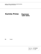
Overview of the device
Fig. 1: Design
It em Designation It em Designation
1 Ret urn lever 7 Co in insert f unnel
2 Int erf ace co nnect o r 8 Disp lay (HI)
3 Co in valid at o r 9 IrDA int er f ace (HI)
4 Keys (HI) 10 Human Int erf ace (
HI
)
5 Tub e casset t e 11 Lever f o r casset t e
removal
6Payout set
1
2
3
4
6
7
8
9
10
11
5

4
National Rejectors, Inc. GmbH, Buxtehude
Control panels of the different models
Blue
version
The human interface, the operating device for the user, consists of a
keyboard with seven keys and a display.
Fig. 2: Control panel for the
Blue
version
Green
version
The control panel of the
Green
version consists of seven keys and three
status/diagnosis LED.
Fig. 3: Control panel for the
Green
version

5National Rejectors, Inc. GmbH, Buxtehude
White
version
The
White
version has no control elements on the control panel. The user
interface is made available via the separate setting module HENRI or via the
respective vending machine (provided this function is supported).
Fig. 4: Control panel of
White
version
Orange
version
Apart from the additional IrDA communication interface the
Orange
version
is identical with the
White
version.
Fig. 5: Control panel of
Orange
version

6
National Rejectors, Inc. GmbH, Buxtehude
START-UP
To avoid damage of any kind during the start-up process,
please carefully check all points specified below:
– suitable connection cable for the respective
interface
– mains voltage in conformity with the specification
on the label
Proceed as follows to install the coin changer in the vending machine:
1 Pull the mains plug of the vending machine.
2 Hang up the coin changer in the vending machine using the three
fastening holes in the rear wall (two at the top and one at the
bottom), see figure below.

7National Rejectors, Inc. GmbH, Buxtehude
3 Lift up the latch and then swivel out the coin validator, see figure
below.
Ensure that the coin validator is properly connected with
the coin changer by the ribbon cable.
4 Fasten the housing of the coin changer in the vending machine with
screws.
5 Swivel the coin validator in again and let it engage.
Ensure that there is an air gap between the return lever of
the vending machine and that of the coin changer.
6 Connect the coin changer to the vending machine using the
required connecting cable and also connect any external devices,
such as hopper or recycler, to the coin changer.
7 If necessary, connect coin changer to power via the feeder (barrel
connector) for PC application.
8 Reconnect the vending machine to the mains supply.
1.
2.

8
National Rejectors, Inc. GmbH, Buxtehude
FIRST STEPS
Since the individual functions of the changer are programmed by the
manufacturer according to customer-specific requirements, you only have
to fill the six change tubes of the tube cassette with the appropriate coin types
when starting up the device for the first time..
Filling the change tubes for the first time...
...with the tube cassette inserted
White
version
Filling is performed using either the c
2
setting module (option) or the
vending machine filling function.
Green
version
Filling of this model is initiated by pressing the -key. Filling can also be
performed by connecting the c
2
setting module (see
Blue
version).
Blue
version
Filling is controlled via menu functions. Press the MENU button to enter the
selection level. Then press key F to activate the filling mode. Fill as usual.
...with the tube cassette dismounted
Filling of the tube cassette before it is inserted into the coin changer:
If you need an exact coin number for accounting, the coin
changer must be configured for this filling method:
– Float level (= number of coins which a tube
contains after filling)

9National Rejectors, Inc. GmbH, Buxtehude
– Activation of automatic tube counter programming
during filling to this float level/tube
– Deactivation of automatic tube counter correction
according to the filling level sensors
Fig. 6: MENU key (
Blue
version) / -key (
Green
version)
1 Press the MENU key ( -key). The coin changer is no longer in
operating mode.
Blue
version: the main menu is displayed. Activate the filling mode by
pressing the key F.
Green
version: the green LED flashes. Filling mode is activated.
2 Remove empty tube cassette and insert prefilled cassette.The tube
counters are set to the coin numbers of the float levels.
3 Press the MENU key ( -key).
Blue
version: return to the main menu. After the MENU key has been
pressed again, the coin changer changes to operating mode.
Green
version: the green LED lights. The coin changer is in
operating mode.

10
National Rejectors, Inc. GmbH, Buxtehude
Instructions for filling via menu or -key
If the cash-box is not empty, it must be emptied. Coins directed to the cash-
box are not counted.
It is not necessary to empty the cash-box, if the changer has
been set so that only coins to be sorted into tubes are
accepted when the tubes are being filled.
1 Press the MENU ( -key).
Blue
version: the main menu is displayed. Activate the filling mode by
pressing the key F.
Green
version: the green LED flashes. Filling mode is activated.
2 Insert valid coins.
The respective tube counter counts the accepted coins, and the coin
changer sorts the respective coin type into the tube configured
accordingly until:
– the full sensor is covered.
– or the configured maximum number of coins is reached.
– or the float level is reached.
Thereafter, the tube coins inserted will, depending on the setting,
either not be accepted and directed into the return area, or be
accepted and directed into the cash-box.
When all tubes are filled:
3 Press -key again.
Lighting of the green LED indicates that the coin changer is no
longer in tube filling mode, but in operating mode.
If no coins are inserted for a period of 30 seconds, the coin
changer returns to operating mode without pressing of the
MENU key ( -key).

11National Rejectors, Inc. GmbH, Buxtehude
ERROR MESSAGES / DIAGNOSTICS
Blue
version
All error messages are output via display in the form of self-explaining
plaintext messages, see figure below.
Fig. 7: Example of an error message in the display
Green
version
Error messages can only be output via the vending machine (if the function
is supported), the c
2
setting module (option) or the three LED.
Quick diagnosis
Fig. 8: Location of LED in the control panel of the
Green
version
Error
No
communication
with VMC

12
National Rejectors, Inc. GmbH, Buxtehude
Color (LED) Status M eaning
red p ermanent lig ht
p ro b lems t hat can b e so lved
o nly b y a t echnician
yello w f lashing
p ro b lems t hat can easily b e
solved by customer
g reen
p ermanent lig ht
o r f lashing
no problems
White
version and
Orange
version
Without control panel the basic version can output error messages only via
the vending machine connected (if the function is supported) or the c
2
setting module (option) .
/