Page is loading ...

Description and Instruction Manual
for the
BAADER
FlipMirror II
FlipMirror II
# 2458055
VARIOUS PORTS - VARIABLE WORK
– EN ver. 07/2019 –
BAADER PLANETARIUM
Zur Sternwarte 4
•
D-82291 Mammendorf
•
Tel. +49 (0) 8145 / 8089-0
•
Fax +49 (0) 8145 / 8089-105
www.baader-planetarium.com
•
kontakt@baader-planetarium.de
•
www.celestron.de
G
M
B
H
# 2458055

2
© Baader Planetarium GmbH | 2019
3
Manual: FlipMirror II
Baader FlipMirror II star diagonal
Various Ports, Variable Work
Congratulations on your purchase of the Baader FlipMirror II (BFM II) star diagonal.
This compact, versatile and congurable ip mirror offers more options than our previ-
ous model, as well as other competing units. In this manual we want to present some
of its possible uses. The most important features of the BFM II are:
• Three connecting ports:
1. Straight light path (S52, M48 and T-2 on both sides) for full-format cameras,
spectrographs and other instruments
2. Adjustable T-2 thread on top for eyepiece clamps, video modules (up to 32 mm
image circle) or even a binoviewer
3. Bottom ange for the optional Off-Axis-Guider for Baader FlipMirror II (BFM-OAG)
# 2956951 or for an optional calibration lamp for quick calibration of spectra wit-
hout removing the spectrograph
• Precise surface-mirrored ip mirror with multi-layer Al coating, for high-resolution
images with cameras with small pixels
• The back of the ip mirror is also Al coated and masked to direct the light of an
optional calibration lamp onto the slit of a spectrograph.
• Enables precise adjustment of all light paths
• Shortest possible overall length for any application – compatible with a large num-
ber of adapters from the Baader Astro T-2 system, the M48 system and the UFC
system (Universal Filter Changer)
• Rotatable M48 connection rings made of hardened, stainless steel on front and rear,
backlash-free adapted to the BFM housing. Can be xed in the optimum position to
rotate any accessory around the optical axis.
• Prepared for an optional toothed belt for
motorization (e.g. by Steeldrive II Control-
ler) – basic requirement for image acquisi-
tion, guiding and spectroscopy in remote
observatories
BFM II with DADOS-
spectrograph and
CCD-camera – no other
flip mirror can carry such
a heavy load (with such
a lever) without bending,
which would ruin the
precise measurements.
Technical Data
SKU # 2458055
Connections S52, M48, T-2
Material Aluminium, stainless steel
Mirror Material Multilayer aluminium coating
with dielectric protective layer
Optical Pathway 55 mm with S52
59 mm with M48/T-2
Weight 195 g
Dimensions
(with all adapters)
63 x 77 x 69 mm
Scope of Delivery
of the Baader FlipMirror II (BFM II)
1. Baader FlipMirror II – with ne-optically polished, movable mirror
2. Laterally adjustable T-2a top ring
3. 2x M48i / S52 Dovetail ring made of hardened stainless steel # 2958552
4. Reducing ring M48a / T-2i # 2958553
5. Reducing ring M48a / T-2a # 2958554
6. Inverter ring M48a / M48a # 2958555
7. Pin type face wrench for M48 / T-2 and M4 counter nuts
8. 3 mm screwdriver for M 4 brass adjustment screws
9. 4x hex keys (2.5 / 2.0 / 1.5 / 1.3 mm).
The 2.0 mm wrench has a ball head to reach screws even when accesso-
ries are mounted by holding the wrench at an angle.
10. AUX-port bottom ange (laterally adjustable 1mm) for off-axis guide or
calibration lamp for spectroscopy
11. 19 mm dust cap for AUX-Port
12. T-2i dust cap
13. M48a dust cap
14. 2 x T-2a dust caps
1
4
3
5 6
7
8
9
1110
12
13 142

4
© Baader Planetarium GmbH | 2019
5
Manual: FlipMirror II
Using the FlipMirror II
The FlipMirror II allows a variety of permanent adapta-
tions to your telescope
1
. Use the rotary knob
2
to
switch between the rear port
3
and the top port
4
;
you can use an optional toothed belt to operate it with
a motor (not included). An autoguider or a calibration
lamp can be connected to the bottom port
5
.
General Function of the FlipMirror II
The BFM II lets you switch between a straight light
path (Position A) for a camera or other measuring
instruments and an angled light path (Position B), e.g.
for an eyepiece. The following gure shows how it works. In addition, a calibration
lamp for spectrographs or an Off-Axis-Guider pickoff-prism (that is not affected by the
mirror position) can be connected at the AUX-port on the bottom.
Connection to the telescope
For connection to the telescope
1
you can choose between an S52 dovetail ring, an
M48 thread or a T-2 thread. To use the M48 thread, remove the pre-installed reducing
ring from M48 to T-2, using the supplied tool
7
.
Based on these threads, various adaptation options are available. We recommend
screw connections so that even heavy accessories can be securely fastened to the
telescope. Furthermore, you can use the following adapters if your telescope does not
already have a T-2 or M48 connection thread:
• Baader Nosepiece 1¼" / T-2 # 2458105
for use with 1¼" eyepiece clamps
• Baader 2" / T-2 Nosepiece and Camera adapter # 2408150
for use with 2" eyepiece clamps
• Baader SC / HD Ultra Short T-Adaptor, 7mm optical length # 2958500B
for use with Schmidt-Cassegrain- and EdgeHD-telescopes
• M68 to T-2 Conversion Ring # 2458233
• Diamond Steeltrack® M48 adapter # 2957204 for direct connection to Diamond
Steeltrack® focusers
You can also remove the M48 thread-adapter (see below image) to access the S52
dovetail ring. This way, you can attach the ipmirror with the largest possible aperture
and the shortest optical path length to t e.g.:
• 2" / S52 Nosepiece # 2958551 for use with 2" eyepiece clamps
• S52 dovetail Camera-Adapter for Wide-T-rings # 2459119
• the UFC Universal Filter Container system in front of the BFM II. To mount the UFC
between FlipMirror and telescope, you need the S52 dovetail Camera-Adapter for
Wide-T-rings # 2459119. You can nd more about this on page 8 (connecting a lter
slider).
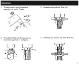
Position A: Mirror is up, so that the rear
port can be used
On the telescope side, the BFM II is equipped with a female T-2 thread (image to the left).
If you remove this threaded ring, you can use the M48-thread (central image). There are four grub screws at the
side of the housing (red arrows) which secure the M48 ring. If you loosen them with the 1,5mm hex key, you can
rotate the BFM II (for both M48 and T-2 thread – see also page 10) and/or use the S52 dovetail ring (right image).
Position B: Mirror is down, so that the
top port can be used
1
4
3
5
2
T- 2 M 48 S 52
55mm (S52)
59mm (M48 / T-2)
Position A:
e.g. for DSLR-/ CCD-/
CMOS-cameras or
spectrographs
AUX-Port:
e.g. for Off-Axis Guider
(independent of the
mirror position) or
calibration lamp
Position B:
e.g. for second
camera (video mo-
dule), observation- or
guiding-eyepiece

6
© Baader Planetarium GmbH | 2019
7
Manual: FlipMirror II
Attaching an Imaging Camera or other Instruments
to the rear Port (Straight Light Path)
The connections on the camera side corres-
pond to those on the telescope side, but with
external threads. A camera with a large sensor
can be mounted via the T-thread or the M48
threaded ring at the rear
3
of the FlipMirror.
The mirror ips upwards; for large, rectangular
sensors, align the long side parallel to the ip-
ped up mirror, if necessary, to use the maxi-
mum aperture.
You can connect your camera using a standard
T-ring or M48 adapter. Spectrographs like the
DADOS can also be screwed directly to the
FlipMirror for the shortest possible connec-
tion. Simply remove the 2" nosepiece from
the spectrograph.
The FlipMirror is delivered with a T-2 male
thread onto which an M48 threaded ring is
screwed. Unscrew the M48 ring if necessary.
As with the telescopic connection, there
are four grub screws which can be used to
rotate or remove the connection threads. An
S52 ring dovetail is then available for further
adaptations.
Attaching an Eyepiece or a Video
Module to the upper Port
To nd or center an object, you can equip the T-thread of the upper port
4
with an
eyepiece clamp of the matching height. For a very short adaptation, you can attach
the illuminated 25mm Polaris I – Measuring- and
Guiding-Eyepiece # 2954325 with T-2-thread. The
eld stop of the eyepiece (which is usually located
at the connection point from the eyepiece body to
its nosepiece) needs about the same distance to
the ip mirror as the camera sensor, so that both
are in focus at the same time. The required distance
depends on the backfocus of your camera. We
recommend the use of a focusing eyepiece holder
# 2458125 for quick and easy correction of focus
(e.g. if you wear glasses) as well as extension tubes
(xed or variable length) from our T-2 or M48 lines.
You can use a T-2 quick changer to switch bet-
ween several combinations (e.g. various eyepieces
or cameras) without having to refocus each time.
With a Varilock on the camera side (right) and
a focusing eyepiece clamp (top), you can easily
bring both ports into focus. CCD sensors require
less back focus than DSLR cameras. To bring the
camera or eyepiece into focus at the upper port,
you may need extension sleeves.
You can also use it to easily rotate the camera into a desired position.
T-2 extensions with fixed length:
• T-2 Extension Tube 40mm # 1508153
• T-2 Extension Tube 15mm # 1508154
• T-2 Extension Tube 7,5mm # 1508155
• T-2 Fine-Adjustment Rings 0,3 / 0,5 / 1 mm # 2457910
T-2 extensions with variable length:
• VariLock 46, lockable T-2 ExtensionTube 29-46mm # 2956946
• VariLock 29, lockable T-2 ExtensionTube 20-29mm # 2956929
• Variable locking T-2 Extension (12-16mm) incl. Lock Ring # 2958130
Eyepiece Clamps:
• Focusing Eyepiece Holder 1¼" # 2458125
• Variable Locking / Sliding T-2 Focuser) # 2458010
• ClickLock Eyepiece Clamp 1¼" with built in diopter-adjustment # 2458100
Quick Changer:
• TQC/TCR Heavy duty T-2 Quick Changing System # 2456322
• Standard T-2 Changer System # 2456321
The Polaris Guiding Eyepiece directly screwed
to the variable 12-16 mm T-2-extension. A
15mm T-2 extensions sets the right working
distance for the camera on the right hand
side.
Incomplete selection of 1¼" eyepiece clamps and T-2 spacers:

8
© Baader Planetarium GmbH | 2019
9
Manual: FlipMirror II
The Off-Axis-Guider
mounted under the BFMII.
The prism is visible in the
housing, under the mirror.
same way. Both models were sold in high
numbers and may be purchased second-
hand at a very good price.
The prism is always below the
mirror so that it can also
be used when the mirror
is down, e.g. to guide a
planetary camera con
-
nected to the upper port.
When the mirror is up,
the camera at the rear
port should be aligned
in such a way that the
prism is under the long
side of the sensor.
When using an Off-Axis-Guider, you need to match its focal
point to that of eyepiece and camera. This can be done with
(variable) extension tubes for camera/eyepiece, or with DT-
4-sleeves for an autoguider camera as described in the
"Focusing" section on the next page.
The back of the mirror is also aluminised and masked, to
bring, for example, the light of a calibration lamp to a spec-
trograph at the rear port. The aluminium-multicoating of the
mirror with its dielectric protective coating ensures a strict
separation of both light paths.
Attaching a filter changer
The BFM II can be combined with the Baader UFC Uni-
versal Filter Changer, or with other lter changers which
provide S52, M48 or T-2 connections.
To mount the Baader UFC behind the BFM II, you will
need either the UFC M48 camera-adapter # 2459116
or the S52 dovetail Camera-Adapter for Wide-T-rings
# 2459119. To
use the S52-
adapter, you will
need to remove
the M48-ring
as described above by loosing the four small
grub screws.
To mount the BFM II in front of the UFC, you
can equip the UFC base unit with the UFC
S70 / M48 (f) Telescope-Adapter # 2459129.
Its female M48 thread ts to the male M48-
thread of the BFM II.
Cross Hair Eyepieces:
• Polaris I – Measuring- and Guiding-Eyepiece,
25mm, T-2, illuminated # 2954325, for direct adapta-
tion to a T-2-thread, or with optional 1¼" nosepiece
# 2458105
• Baader Micro Guide Eyepiece with Log-Pot illumina-
tor # 2404300
You can also use the T-thread on the top port to attach
a bino-viewer (with a glasspath corrector), if there is
enough back focus and and if you nd a comfortable
viewing position. This is especially interesting for lar-
ger telescopes with Nasmyth- or Coudé-focus!
Attaching an Autoguider, a calibration
lamp or other accessories to the bottom port
There is a third port
5
at the bottom of the FlipMirror, where you can attach e.g. the
pick-up-prism of an autoguider or a calibration lamp for a spectrograph. You can attach
accessories either via the three screw holes (M 3,
15 mm radius) or with the three locking screws at
the side of the 19mm large adapter plate.
You can attach the Off-Axis-Guider for Baader
FlipMirror II (BFM-OAG) # 2956951 directly to the
FlipMirror. You only have to remove the included
small spacer ring (as shown in the image to the
left), so that the prism is fully inserted into the light
path of the BFM II.
Then simply remove the lower dust cap from the
lower port of the BFM II, loosen the three lateral
hexagon socket screws (see photo), slide the BFM-
OAG into the port and tighten the screws again. The
Guider has a tilting prism for easier adjustment of a
guide star. Please note that the vertical side of the
prism must face the telescope.
The BFM-OAG is also part of the Off Axis Guider for
RCC (RCC-OAG) # 2956950. To use this item with
the BFMII, you will need to remove the unit with the
pick-up prism from the T-2-ring as described on the
next page; then you need to remove the spacer ring
from the pick-up prism exactly as with the Off-Axis-
Guider for BFM II. As described above, you can then
insert the prism unit into the BFM II and lock it with
the three screws. Remember that the vertical side of
the prism must face towards the telescope.
The old Celestron Radial Guider #94176 – which
is no longer in production – can be attached the
Another option:
Attaching a bino-viewer with a glasspath
corrector.
To use the pick-up prism of the Baader Off Axis Guider
for RCC (left) or of older Celestron Radial Guiders, you
first need to remove the T-2-sleeve by opening screw
1. Now loosen the the screws 2 to remove the spacer
ring (grey arrow), and reattach the prism unit again at
the eyepiece clamp. Screw 3 is used to tilt the prism.
2
1
3
The UFC can be mounted on both
sides of the BFM II
The UFC with a 50x50 filter slider, which requires a
only a minimum of space when the UFC is attached
directly to the BFM II
The adapter flange at the lower plate. The
red arrows mark the locking screw for
a pick-up prism. Loosen the larger hex
screws to temove the flange, e.g. to adapt
a calibration lamp. You can also see the
masked mirror inside of the BFM II.
The Off-Axis-Guider for Baader FlipMirror II.
Here, the spacer ring (right) has already
been removed. (# 2956951)

10
© Baader Planetarium GmbH | 2019
11
Manual: FlipMirror II
Use the 1,5mm Allen key to loosen the grub screws and retighten them again. They
grip into the S52 dovetail ring made of steel. Loosen these screws only so much that
you can rotate the threaded and. Once you're satised with the orientation, tighten
them again hand-tight.
2) Adjusting the upper T-2-thread
The adjustable T-2 top-ring can be moved sideways on
the housing, to center an eyepiece or video module onto
an object which is centered in the main instrument.
Firstly, center a star in the main unit mounted on the rear
port with the mirror up (position A). Then ip down the
mirror (position B) and view the image e.g. in the eyepi-
ece or camera on the top port. If the star is not placed
in the center, loosen the four screws with the supplied
2mm hexagon wrench, move T-2 top-ring adapter plate
with the T-thread on the housing and x it in the desired
position by tightening the screws again.
3) Adjusting the mirror
The mirror is held in position by a spring mechanism.
When it is ipped down, it rests on two conical pins. If
necessary, the inclination of the mirror can be adjusted
by adjusting the two pins in opposite directions. The two
tools
7
and
8
are used for this purpose.
Always turn both screws by the same amount and then
check whether the mirror rests on the sharpened sur-
faces of the two brass screws. This allows the image to
be moved along the optical axis. For this adjustment our
LaserColli Mark III # 2450343 can be used for example.
4) Adjusting the bottom port
You can adjust the bottom port similarly when an
off-axis guider is connected. To do this, check the
orientation of the prism and make sure that the vertical
surface points towards the telescope – if necessary,
loosen the small grub screws to rotate the prism unit.
Then center the reference object in the rear beam path
and check where it appears in the guiding camera.
If necessary, loosen the three fastening screws (red
arrows) with the 2mm hexagon wrench supplied.
They have a rounded head so that you can loosen
the screws even if a wider instrument is connected to the lower port. Then move the
Off-Axis-Guider as necessary to center the star (you may have to check the tilt of the
prism of the radial guider).
Focusing
The focus position at the upper and rear ports is approximately the same if the T-2 ad-
apters are used for each port. However, we recommend that you make one connector
focusable in order to be able to accommodate tolerances, deviating focus positions of
eyepieces or diopter compensation.
If you do not use an off-axis guider, you can simply attach the eyepiece to the top and
the camera to the rear port of the BFM II. First focus the camera with the telescope's
focuser, then x its position if possible. Now focus the eyepiece, e.g. over a focusing
eyepiece clamp, or by pulling it slightly out. With most 1¼" eyepieces, the focus plane
is approximately at the transition from the housing to the nosepiece. Take into account
the length of the eyepiece clamp and the back focus of the camera for the setup.
If you are using an off-axis guider, you must also consider the
focus position of the guiding camera. If you use the Off-Axis-
Guider for Baader FlipMirror II (# 2956951) as well as a guiding
camera whose image plane is at the upper end of the Off-Axis-
Guider (i.e. without additional back focus), the image plane of the
camera and eyepiece is about 24mm behind the two T-2 threads
of the BFM II. A CCD camera with a short back focus, for examp-
le, can be adjusted to this distance with a VariLock 29, as can
the Polaris I crosshair eyepiece when connected directly to the
VariLock 29 via T-2. Thus, a very short adaptation is possible.
If you use a DSLR via a T-2 adapter, or an eyepiece clamp for
the eyepiece, you need more back focus. Then, the guiding
camera must be placed at a greater distance from the BFM II.
The easiest way to do this is to use the DT-4 nosepiece exten-
sion # 1905130 with an overall length of 18.5mm. It has the diameter of a 1¼" eyepie-
ce and is screwed into the 1¼" lter thread of the guiding camera. With one or two of
these extensions, you can place virtually any camera over the off-axis guider so that it
is parfocal with the recording camera. Tip: With the FR-4 adjusting ring 1¼" # 1905131
you can x the insertion depth so that you "save" a focus position.
Adjustment of the FlipMirror II
There are many set screws to adjust the BFM II
perfectly to your imaging setup.
1) Rotating the Housing and Camera/Main
Instrument
The M48 threads on both sides (and with them
also the T-2 threads inserted into them) can be
rotated and xed in the socket via the four M3
grub screws on the sides, so you can rotate the
FlipMirror housing into any desired position when
screwed to the telescope. An instrument rmly
connected to the straight beam path can also be
rotated into the desired position.
The orientation of the adapter threads on
both sides can be changed with the four grub
screws. This way, you can align instruments like
the DADOS spectrograph in this image to the
BFM II, or you can rotate the whole BFM, if it is
screwed directly to the telescope.
BFM II – seen from above. Use the
screws for adjusting the thread.
Setting and "saving" the focus
position of an eyepiece or
camera module with an FR-4
Focusing Ring Collar and a
DT-4 extension
The two pins on which the mirror
lays on
The screws for adjusting the bottom
port of the BFM II.

12
Manual: FlipMirror II
www.baader-planetarium.com
Strain Relief for Cables
The two screws on the side of the housing can be used
to attach additional accessories. You can, for examp-
le, connect a strain relief holder for cables by forming
a loop out of a small plastic strip or alternatively
purchase a nished cable holder.
Motorization
The two screws and the at recess in the side of the
housing are intended for the connection of a future motorization, e.g. in combination
with the Steeldrive II motor focusing unit # 2957165. It can be connected via a toothed
belt which runs over the recess on the knob of the BFM II.
The Future
We have tried to show you examples of how the BFM II can be used. Of course, there
are many more possibilities, which we will present in due course and in future blog
posts on our website.
To stay up to date, why not sign up for our newsletter at
www.baader-planetarium.com/en/newsletter.
A small plastic loop can act as strain relief
for cables
All technical specications in this manual are subject to change without notice, we reserve the right for errors.
© 2019 Baader Planetarium GmbH, Mammendorf. Except for brief quotations in critical articels or reviews, no
reproduction of this manual, in any form, in whole or in part, may be made without written authorization of
BAADER PLANETARIUM
Zur Sternwarte 4
•
D-82291 Mammendorf
•
Tel. +49 (0) 8145 / 8089-0
•
Fax +49 (0) 8145 / 8089-105
www.baader-planetarium.com
•
kontakt@baader-planetarium.de
•
www.celestron.de
G
M
B
H
The BFM II is prepared for future motorization.
The selection knob has a recess for a drive belt.
/