
W415-1966 / 07.08.19
ADD MANUAL TITLE
Wolf Steel Ltd., 24 Napoleon Rd., Barrie, ON, L4M 0G8 Canada / 103 Miller Drive, Crittenden, Kentucky, USA, 41030
Phone 1 (866) 820-8686 • www.napoleon.com • [email protected]
CERTIFIED TO THE AMERICAN NATIONAL STANDARD:
ANSI _______ FOR _____________________________________________________
INSTALLER:
Leave this manual with the appliance
CONSUMER:
Retain this manual for future reference
ADD PRODUCT CODE HERE (TRADE GOTHIC LT STD FONT)
NATURAL GAS MODELS:
PROPANE GAS MODELS:
Product Name / Code
(MUST use title from Price Book)
ADD ____ ILLUSTRATED
ADD PRODUCT IMAGE
CERTIFICATION
LOGO
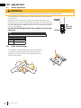
SAFETY INFORMATION
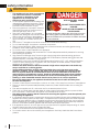
- Do not store or use gasoline or other
fl ammable vapors and liquids in the vicinity of
this or any other appliance.
- WHAT TO DO IF YOU SMELL GAS:
• Do not try to light any appliance.
• Do not touch any electrical switch; do not
use any phone in your building.
• Immediately call your gas supplier from a
neighbour’s phone. Follow the gas
supplier’s instructions.
• If you cannot reach your gas supplier, call
the fi re department.
- Installation and service must be
performed by a qualifi ed installer, service
agency, or the supplier.
- This is an unvented gas-fi red heater that
uses air (oxygen) from the room in which
it is installed. Provisions for adequate
combustion and ventilation air must be
provided. Refer to section “combustion
and ventilation air provisions”.
FIRE OR EXPLOSION HAZARD
Failure to follow safety warnings exactly
could result in serious injury, death, or
property damage.
WARNING
!
ENGLISH
$10.00
FOR INDOOR USE ONLY
IF INSTALLATION + OPERATION, ADD SERIAL
NUMBER LABEL HERE
IF SEPARATE MANUALS, ADD “PLACE
BARCODE LABEL ON THE OWNER’S MANUAL”
Insert appropriate statement (see margins).
This appliance may be installed in an aftermar-
ket, permanently located, manufactured-home
(USA only) or mobile home, where not
prohibited by local codes.
This appliance is only for use with the type of
gas indicated on the rating plate. This appliance
is not convertible for use with other gases.
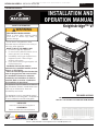
GVFS60-1N / GVFS60-1NN
GVFS60-1P / GVFS60-1PN
INSTALLATION AND
OPERATION MANUAL
Knightsbridge™ VF
SAFETY BARRIER
CERTIFIED TO THE AMERICAN NATIONAL STANDARDS:
ANSI Z21.11.2b VOLUME II FOR UNVENTED ROOM HEATERS

W415-1966 / 07.08.19
EN
2
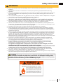
safety information
• This appliance is hot when operated and
can cause severe burns if contacted.
• Any changes or alterations to this
appliance or its controls can be
dangerous and is prohibited.
• Do not operate appliance before reading and
understanding operating instructions. Failure
to operate appliance according to operating
instructions could cause fi re or injury.
• Ensure the glass door is opened or removed
when lighting the pilot for the fi rst time and
when the gas supply has run out.
• Risk of fi re or asphyxiation, do not operate
appliance with fi xed glass removed and never
obstruct the front opening of the appliance.
• Do not connect 110 volts to the control valve,
with the exception of models; GSST8 and
GT8.
• Risk of burns. The appliance should be turned off and cooled before servicing.
• Do not install damaged, incomplete or substitute components.
• Risk of cuts and abrasions. Wear protective gloves, protective footwear, and safety glasses during
installation. Sheet metal edges may be sharp.
• Do not burn wood or other materials in this appliance.
• Provide adequate ventilation and combustion air. Provide adequate accessibility clearance for servicing
and operating the appliance.
• High pressure will damage valve. Disconnect gas supply piping before pressure testing gas line at
test pressures above 1/2 psig. Close the manual shut-off valve before pressure testing gas line at test
pressures equal to or less than 1/2 psig (35mb).
• The appliance must not be operated at temperatures below freezing (32°F / 0°C). Allow the appliance
to warm to above freezing prior to operation, with the exception of models; GSS36, GSS42; these
appliances are suitable for 0°F / -18°C.
• Children and adults should be alerted to hazards of high surface temperature and should stay
away to avoid burns or clothing ignition.
• Young children should be carefully supervised when they are in the same room as the
appliance. Toddlers, young children and others may be susceptible to accidental contact
burns. A physical barrier is recommended if there are at risk individuals in the house. To
restrict access to an appliance or stove, install an adjustable safety gate to keep toddlers,
young children and other at risk individuals out of the room and away from hot surfaces.
• Clothing or other fl ammable material should not be placed on or near the appliance.
• Due to high temperatures, the appliance should be located out of traffi c and away from
furniture and draperies.
• Furniture or other objects must be kept a minimum of 4 feet (1.22m) away from the front of the appliance.
• Ensure you have incorporated adequate safety measure to protect infants/toddlers from touching hot
surfaces.
• Even after the appliance is off, it will remain hot for an extended period of time.
• Check with your local hearth specialty dealer for safety screens and hearth guards to protect children
from hot surfaces. These screens and guards must be fastened to the fl oor.
• Any safety screen, guard or barrier removed for servicing the appliance, must be replaced prior
to operating the appliance.
• It is imperative that the control compartments, burners and circulating blower and its passageway in the
appliance and venting system are kept clean. The appliance and its venting system should be inspected
before use and at least annually by a qualifi ed service person. More frequent cleaning may be required
due to excessive lint from carpeting, bedding material, etc. The appliance area must be kept clear and
free from combustible materials, gasoline and other fl ammable vapors and liquids.
• If the appliance shuts off, do not re-light until you provide fresh air. If appliance keeps shutting off, have it
serviced. Keep burner and control compartment clean.
• Under no circumstances should this appliance be modifi ed.
• Do not allow wind or fans to blow directly into the appliance. Avoid any drafts that alter burner fl ame
patterns.
HOT GLASS WILL CAUSE
BURNS.
DO NOT TOUCH GLASS UNTIL
COOLED.
NEVER ALLOW CHILDREN TO
TOUCH GLASS.
!
DANGER
A barrier designed to reduce the risk of burns from the
hot viewing glass is provided with this appliance and
shall be installed for the protection of children and other
at-risk individuals.
!
WARNING

EN
W415-1966 / 07.08.19
3
safety information
!
WARNING
• Do not use a blower insert, heat exchanger insert or other accessory not approved for use with this
appliance.
• This appliance must not be connected to a chimney fl ue pipe serving a separate solid fuel burning
appliance.
• Do not use this appliance if any part has been under water. Immediately call a qualifi ed service technician
to inspect the appliance and to replace any part of the control system and any gas control which has
been under water.
• Do not operate the appliance with the glass door removed, cracked or broken. Replacement of the glass
should be done by a licensed or qualifi ed service person, if equipped.
• Do not strike or slam shut the appliance glass door, if equipped.
• Only doors / optional fronts certifi ed with the appliance are to be installed on the appliance.
• Keep the packaging material out of reach of children and dispose of the material in a safe manner. As
with all plastic bags, these are not toys and should be kept away from children and infants.
• Carbon or soot should not occur in a vent free appliance as it can distribute into the living area of your
home. If you notice any signs of carbon or soot, immediately turn off your appliance and arrange to have
it serviced by a qualifi ed technician before operating it again.
• If equipped, the screen must be in place (closed) when the appliance is in operation.
• When equipped with pressure relief doors, they must be kept closed while the appliance is operating
to prevent exhaust fumes containing carbon monoxide, from entering into the home. Temperatures of
the exhaust escaping through these openings can also cause the surrounding combustible materials to
overheat and catch fi re.
• Carbon monoxide poisoning may lead to death; early signs of carbon monoxide poisoning resemble the
fl u, with headache, dizziness and/or nausea. If you have these signs, the appliance may not be working
properly. Get fresh air at once! Have appliance serviced. Some people; pregnant women, persons with
heart or lung disease, anemia, those under the infl uence of alcohol, those at high altitudes are more
affected by carbon monoxide than others. Failure to keep the primary air opening(s) of the burner(s) clean
may result in sooting and property damage.
• As with any combustion appliance, we recommend having your appliance regularly inspected and
serviced as well as having a Carbon Monoxide Detector installed in the same area to defend you and
your family against Carbon Monoxide (not applicable for outdoor appliances).
• Ensure clearances to combustibles are maintained when building a mantel or shelves above the
appliance. Elevated temperatures on the wall or in the air above the appliance can cause melting,
discolouration or damage to decorations, a TV or other electronic components.
• For appliances equipped with a safety barrier; if the barrier becomes damaged, the barrier
shall be replaced with the manufacturer’s barrier for this appliance.
• Installation and repair should be done by a qualifi ed service person. It is imperative that control
compartments, burners and circulating air passageways of the appliance be kept clean.
• For outdoor products only: this appliance must not be installed indoors or within any structure that
prevents or inhibits the exhaust gases from dissipating in the outside atmosphere.
• If applicable, the millivolt version of this appliance uses and requires a fast acting thermocouple. Replace
only with a fast acting thermocouple supplied by Wolf Steel Ltd.
!
WARNING
!
Disconnect the appliance main gas valve/control
from the supply piping when pressure testing that
system at pressures in excess of 1/2 psi (3.5 kPa).
Isolate the appliance with it’s shut off valve during
any pressure testing of the supply piping at
pressures equal to or less than 1/2 psi (3.5 kPa).
FIRE RISK HAZARD / DELAYED IGNITION
High supply pressure will damage the valve / controls.
Add California Prop 65 warning
!
WARNING:
This product can expose you to chemicals including lead and lead compounds,
which are known to the State of California to cause cancer, and chemicals including carbon
monoxide, which are known to the State of California to cause birth defects or other reproduc-
tive harm. For more information, go to www.P65Warnings.ca.gov.

W415-1966 / 07.08.19
EN
4
table of contents
1.0 general information 5
1.1 rates and effi ciencies 5
1.2 rating plate information 7
1.3 mobile home installation 7
1.4 dimensions 8
1.5 shipping bracket 8
2.0 installation 9
2.1 determining confi ned or unconfi ned space 9
3.0 gas installation 11
4.0 optional wall switch 12
5.0 finishing 13
5.1 cast front removal 13
5.2 logo placement 13
5.3 log placement 14
6.0 blower installation 15
6.1 switch and bracket installation 16
7.0 operation 17
8.0 adjustment 18
8.1 venturi adjustment 18
8.2 fl ame characteristics 18
9.0 maintenance 19
9.1 oxygen depletion sensor pilot cleaning 19
10.0 replacement parts 20
10.1 GVFS60-1 overview 21
11.0 accessories 22
12.0 troubleshooting 23
13.0 warranty 25
The information throughout this manual is believed to be correct at the time of printing. Wolf Steel Ltd. reserves
the right to change or modify any information within this manual at any time without notice. Changes, other than
editorial, are denoted by a vertical line in the margin.
note:

EN
W415-1966 / 07.08.19
5
table of contents
1.0 general information
Installer, please fi ll out the following information:
Customer:
Address:
Date of Installation:
Location of appliance:
Installer:
Dealer/Distributor contact number:
Serial #:
Model:
Natural Gas: GVFS60-1N Propane: GVFS60-1P
When the appliance is installed at elevations above 2,000ft, and in the absence of specifi c recommendations from the local
authority having jurisdiction, the certifi ed high altitude input rating shall be reduced at the rate of 4% for each additional
1,000ft. Expansion / contraction noises during heating up and cooling down cycles are normal and to be expected.
No external electricity (110 volts or 24volts) is required for the gas system operation.
This appliance is equipped with a pilot light safety system referred to as an oxygen depletion sensor and is designed to
turn off the appliance if not enough fresh air is available.
This appliance is only for use with the type of gas indicated on the rating plate. This appliance is not
convertible for use with other gases, unless a certifi ed kit is used.
The protective wrap on plated parts is best removed when the assembly is at room temperature but this can be
improved if the assembly is warmed, using a hair dryer or similar heat source.
This appliance is a decorative product. It is not a source of heat and not intended to burn solid fuel.
A barrier designed to reduce the risk of burns from the hot viewing glass is provided with the
appliance and must be installed.
note:
1.1 rates and effi ciencies
GVFS60-1
NG P
Altitude (FT) 0 - 2,000 0 - 2,000
Max. Input (BTU/HR) 30,000 30,000
Min. Inlet Gas Supply Pressure 4.5" Water Column 11" Water Column
Max. Inlet Gas Supply Pressure 7" * Water Column 13" Water Column
Manifold Pressure (Under Flow Conditions) 3.5" Water Column 10" Water Column
For your satisfaction, this appliance has been test-fi red to assure its operation and quality!
* Max. inlet pressure not to exceed 13”.
GVFS60-1NN
GVFS60-1PN

W415-1966 / 07.08.19
EN
6
general information
THIS GAS APPLIANCE SHOULD BE INSTALLED AND SERVICED BY A QUALIFIED INSTALLER to
conform with local codes. Installation practices vary from region to region and it is important to know the
specifi cs that apply to your area, for example in Massachusetts State:
• This product must be installed by a licensed plumber or gas fi tter when installed within the commonwealth of
Massachusetts.
• The appliance off valve must be a “T” handle gas cock.
• The fl exible connector must not be longer than 36” (91.4cm).
• A Carbon Monoxide detector is required in all rooms containing gas fi red appliances.
• The appliance is not approved for installation in a bedroom or bathroom unless the unit is a direct vent
sealed combustion product.
• Un-vented room appliances shall be installed in accordance with 527 CMR 30.00 and 248 CMR 3.00
through 7.00.
• Sellers of un-vented propane or natural gas-fi red space / room appliances shall provide to each purchaser a
copy of 527 CMR 30.00 upon the sale of the appliance from http://www.napoleonfi replaces.com/Webshare/
installation_manuals/mass_requirements.pdf
In absence of local codes, install the appliance to the current National Fuel Gas Code, ANSI Z223.1 Installation
Code which can be obtained from:
American National Standards Institute Inc. or National Fire Protection Association Inc.
1430 Broadway Batterymarch Park
New York, NY 10018 Quincy, MA 02269
The appliance and its individual shutoff valve must be disconnected from the gas supply piping system during
any pressure testing of that system at test pressures in excess of 1/2 psig (35 mb). The appliance must be
isolated from the gas supply piping system by closing its individual manual shutoff valve during any pressure
testing of the gas supply piping system at test pressures equal to or less than 1/2 psig (35 mb). When installed
with a blower or fan, the junction box must be electrically connected and grounded in accordance with local
codes. In the absence of local codes, use the current ANSI / NFPA 70 National Electric Code. In the case
where the blower is equipped with a power cord it must be connected into a properly grounded receptacle. The
grounding prong must not be removed from the cord plug.
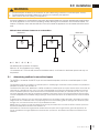
As long as the required clearance to combustibles is
maintained, the most desirable and benefi cial location for
the appliance is in the center of a building, thereby allowing
the most effi cient use of the heat created. The location of
windows, doors and the traffi c fl ow in the room where the
appliance is to be located should be considered.
If the appliance is installed directly on carpeting, vinyl tile or
other combustible material other than wood fl ooring, the
appliance shall be installed on a metal or wood panel extending the full width and depth.
Air shortage caused by an inadequate air supply, improper log positions, the addition of foreign or unapproved
materials or the failure to properly maintain the appliance, may result in incomplete combustion of the fuel.
We suggest that our gas
hearth products be installed
and serviced by professionals
who are certied in the U.S.
by the National Fireplace
Institute
®
(NFI) as NFI Gas
Specialists
www.ncertied.org
This does not apply to stoves.
note:
• Carbon monoxide poisoning may lead to death. Early signs of carbon monoxide poisoning resemble the fl ue,
with headache, dizziness, and/or nausea. If you have these symptoms, the heater may not be working properly.
Get fresh air at once! Have heater serviced. Some people - pregnant women, persons with heart or lung lisease,
anemics, those under the infl uence of alcohol, those at high altitutes - are more affected by carbon monoxide
than others.
• The appliance is only for use with the type of gas indicated on the rating plate. This appliance is not convertible
for use with other gases.
• Objects placed in front of the heater should be kept a minimum of 48" away from the front face of the appliance.
• Use only Wolf Steel approved optional accessories and replacement parts with this appliance. Using non-listed
accessories and replacement parts (blowers, louvres, trims, gas components, vent components, etc.) could
result in a safety hazard and will void the limited lifetime warranty.
• Not designed for use with a glass door. Screen must be closed when appliance is in operation.
• This appliance must not be installed in a bedroom or bathroom.
!
WARNING

EN
W415-1966 / 07.08.19
7
general information
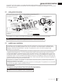
1.2 rating plate information
This illustration is for reference only. Refer to the rating plate on the appliance for accurate information.
The rating plate must remain with the appliance at all times. It must not be removed.
note:
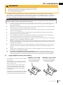
1.3 mobile home installation
This appliance must be installed in accordance with the manufacturer’s instructions and the Manufactured
Home Construction and Safety Standard, Title 24 CFR, Part 3280, in the United States or the Mobile Home
Standard, CAN/CSA Z240 MH Series, in Canada. This appliance is only for use with the type(s) of gas
indicated on the rating plate.
This mobile/manufactured home listed appliance comes factory equipped with a means to secure the appliance. Built
in appliances are equipped with 1/4” (6.4mm) diameter holes located in the front left and right corners of the base.
Use appropriate fasteners, inserted through the holes in the base to secure. For free standing products contact your
local authorized dealer / distributor for the appropriate securing kit. For mobile home installations, the appliance must
be fastened in place. It is recommended that the appliance be secured in all installations. Always turn off the pilot and
the fuel supply at the source, prior to moving the mobile home. After moving the mobile home and prior to lighting the
appliance, ensure that the logs are positioned correctly.
This appliance is certifi ed to be installed in an aftermarket permanently located, manufactured (mobile) home,
where not prohibited by local codes.
This appliance is only for use with the type of gas indicated on the rating plate. This appliance is not convertible
for use with other gases, unless a certifi ed kit is used.
Conversion Kits
This appliance is fi eld convertible between Natural Gas (NG) and Propane (P).
To convert from one gas to another, consult your Authorized dealer/distributor.
note:
Conversion kits are not available for Vent Free appliances.
WARNING: Do not add any materials to the appliance, which will
come in contact with the flames, other than that supplied by the
manufacturer with the appliance. Screen must be in place while the
appliance is in operation.
Electrical Rating: 115V 0.82AMP, 60HZ
Optional Fan Kit: GS-64KT
Minimum clearance to combustible materials:
Minimum 46” from appliance top to ceiling.
* At a distance of 2” from the wall, access to the blower switch,
on-off switch or the blower power cord may not be practical.
Certified to American National Standards: ANSI Z21.11.2-2016 VOLUME II for Unvented Room Heaters
A 6”
B 6"
C 2"*
D 4’
L
O
T
N
O
P
O
I
F
F
O
L
I
H
FLAME ADJUSTMENT
NOT FOR USE WITH SOLID FUEL.
SERIAL NUMBER
GVFS60
W385-0184 / I
ON/OFF CONTROL
IGNITOR
WOLF STEEL LTD.
24 NAPOLEON ROAD, BARRIE. ONTARIO L4M 0G8 CANADA
9700539 (WSL) 4001657 (NGZ)
4001658 (NAC) 4001659 (WUSA)
DIAGRAM TO AID IN THE OPERATION
OF THIS FIREPLACE:
Manifold Pressure: 3.5" w.c.
Minimum Supply Pressure: 4.5" w.c.
Maximum Supply Pressure: 7.0" w.c.
SIT Control: #820637
Operating Pilot Oxyprotector: # 8214
Manifold Pressure: 10" w.c.
Minimum Supply Pressure: 11" w.c.
Maximum Supply Pressure: 13" w.c.
SIT Control: #820636
Operating Pilot Oxyprotector: #8404
**Above 2,000ft, consult local authority having jurisdiction.
GVFS60N CVFS600N MODEL GVFS60P CVFS600P
GVFS60NN CVFS600NN GVFS60PN CFVS600PN
** 0-2000FT (0-610M) Altitude ** 0-2000FT (0-610M)
30,000 BTU/h Input 30,000 BTU/h
20,000 BTU/h Reduced Input 20,000 BTU/h
BACK WALL
BACK WALL
ALCOVE
A
C
A
A
B
B
45°
D
OBJECT
This is a gas-fired, unvented room heater that
requires adequate combustion and ventilation
air. This appliance is not field convertible for
use with other fuels.
This appliance is not approved for bedroom, bathroom,
and bed-sitting room installation.
For use only with barrier(s) Part No(s) W565-0110.
Follow installation instructions.
SAMPLE
W
ARNIN
G
:
NING:
Do not adDo not a
come in connc
als:
als:
E
E
E
E
E
E
E
E
E
E
E
E
E
E
E
E
E
E
E
E
E
E
E
E
E
E
NN
OO
NN
N
E
E
E
L
L
L
L
L
L
L
L
L
L
L
L
L
L
L
L
L
L
L
L
L
L
L
L
L
L
L
L
L
L
L
L
L
L
L
L
L
L
L
L
L
L
L
LE
LE
LE
LE
LE
LE
LE
E
E
E
E
E
E
E
E
E
E
E
E
E
E
E
E
E
E
E
E
E
E
E
E
E
E
E
E
E
E
E
E
E
E
E
E
E
E
E
E
E
E
LE
LE
LE
L
L
L
L
LE
LE
E
L
L
L
L
L
L
L
L
L
L
L
L
L
L
L
L
L
L
L
L
L
L
L
L
L
L
L
L
L
L
L
L
L
L
L
L
L
L
L
L
L
L
LE
LE
LE
LE
LE
LE
LE
E
E
OO
LL
OO
O
I
H
L
E
FLAF
LE
LE
NOT FOR USE WITH SONOT FOR USE WITH S
0" w.c.
Control:ntrol:
#
820637 #820637
xyprotector:
rotector:
#
82
1
4 # 8214
ld Pressure::
1
0"
w.
c. 10" w.c.
Minimum Supply Pressure:nimum Supply Pressure:
11" w.
c
.
11" w.c.
Maximum Supply Pressure:
aximum Supply Pressure:
1
3"
w.
c. 13" w.c.
S
IT
C
ontrol
:T Control:
#82
0636 #820636
O
peratin
g
Pilot Oxyprotector
:perating Pilot Oxyprotector:
#84
04 #8404
ve 2,000ft, consult local authority having jurisdiction.
e 2,000ft, consult local authority having jurisdiction.
610M)0M)
30,000 BTU/hBTU/h
20,000 BTU/h20,000 BTU/h
S
S
SA
SA
SA
BA
C
K WAL
LBACK WALL
SA
SA
SA
SA
SA
SA
SA
SA
S
S
S
S
S
S
S
S
SA
SA
SA
CC
A
B
S
S
S
4
5°45°
S
S
S
DD
S
ECT
Incomplete combustion results in soot being deposited inside the fi rebox as well as surfaces outside the
appliance. If any soot deposits are observed, shut off the appliance immediately and arrange for it to be serviced
by a qualifi ed technician.

W415-1966 / 07.08.19
EN
8
general information
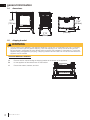
1.4 dimensions
30 1/2"
(774.7mm)
27"
(685.8mm)
17 7/8"
(454mm)
17 3/4"
(450.9mm)
SHIPPING BRACKET REMOVAL
A. Remove the four screws holding the shipping bracket to the bottom of the appliance.
B. Lift the appliance off the skid and set on a fl at surface.
C. Discard the screws, brackets, and skid.
SHIPPING BRACKET
1.5 shipping bracket
• The top casting is not fastened to the appliance assembly. It simply sits on the appliance as a lid. For shipping
purposes, it is held in place by plastic strapping. Once the strapping is cut, the top should be lifted off care-
fully and stored in a safe place to avoid damage while completing the installation of the appliance. To avoid the
appliance being damaged during shipping, a shipping bracket has been used and must be unbolted before the
appliance can be installed.
!
WARNING

EN
W415-1966 / 07.08.19
9
2.0 installation
As long as clearance to combustibles is kept within the required distances, the most desirable and benefi cial loca-
tion for an appliance is in the centre of a building, thereby allowing the most effi cient use of the heat created. The
location of windows, doors and the traffi c fl ow in the room where the appliance is to be located should be consid-
ered.
Maintain these minimum clearances to combustibles:
A. 6” B. 6” C. 2”* D. 4’
No additional fl oor protection is required.
Minimum 46” from appliance top to ceiling.
* At a distance of 2” from the wall, access to the blower switch, on-off switch or the blower power cord may not
be practical.
BACK WALL
BACK WALL
ALCOVE
A
C
A
A
B
B
45°
D
OBJECT
2.1 determining confi ned or unconfi ned space
The GVFS60-1 is rated at 30,000 BTUs per hour and therefore requires a minimum unconfi ned space of 1,500
cubic feet.
• Provide adequate ventilation and combustion air (see “determining confi ned or unconfi ned space” section).
• Provide adequate accessbility clearance for servicing and operating the appliance.
• Never obstruct the front opening of the appliance.
!
WARNING
This appliance shall not be installed in a confi ned space or unusually tight construction unless provisions are provided for
adequate combustion and ventilation air.
The National Fuel Gas Code, ANSI Z223.1
/ NFPA 54 defi nes a confi ned space as a space whose volume is less than 50
cubic feet per 1,000 Btu per hour (4.8 m3 per kw) of the aggregate input rating of all appliances installed in that space
and an unconfi ned space as a space whose volume is not less than 50 cubic feet per 1,000 Btu per hour (4.8 m3 per
kw) of the aggregate input rating of all appliances installed in that space. Rooms communicating directly with the space
in which the appliances are installed, through openings not furnished with doors are considered a part of the unconfi ned
space.
To determine the volume of the room where the appliance is to be installed, multiply the width x the length x the ceiling
height of that room measured in feet. If any adjoining rooms are connected by grilles or openings such as kitchen pass-
throughs, etc., the volume of those rooms may be added to the total.
Multiply the room volume by 1000 and divide this amount by 50 to determine the maximum BTU/hr that the space can
support with adequate combustion and ventilation air.
Add the Btu/hr of all fuel burning appliances located within the space such as gas furnace, gas water appliance, etc.
Do not include direct vent gas appliances which draw their input air from the outdoors and expel their exhaust to the
outdoors.

W415-1966 / 07.08.19
EN
10
installation
Unusually tight construction is defi ned as construction where:
A) Walls and ceilings exposed to the outside atmosphere have a continuous water vapour retarder with a rating of 1
perm (6 x 10-11 kg per pa-sec-m2) or less with openings gasketed or sealed
B) Weather stripping has been added on openable windows and doors
C) Caulking or sealants are applied to areas such as joints around window and door frames, between sole plates and
fl oors, between wall-ceiling joints, between wall panels, at penetrations for plumbing, electrical, and gas lines, and at
other openings.
An unvented room appliance is recommended for use as a secondary heat source rather than as a primary source. Gas
combustion produces water vapour which could occur at the rate of approximately one ounce of water for every 1,000
BTU/hr of gas input. During the cold weather season, indoor humidity levels tend to be low. Consequently, this water
vapour can enhance the living space. However if a problem should occur:
A) Ensure suffi cient combustion and circulation air
B) Use a dehumidifi er
C) Do not use the unvented room appliance as a primary heat
source. Without suffi cient fresh air for proper operation, poor fuel
combustion can result. Carbon Monoxide is a result of poor fuel
combustion.
If additional fresh air is required, use one of the methods
described in the National Fuel Gas Code, ANSI Z223.1 / NFPA54
or the applicable local code.
Room Volume = Length x Width x Height
Max BTU/hr = Room Volume x 1000 / 50
If for example:
The length of the rooms is 5 feet (1.5m),
The width of Room 1 is 10 feet (3.1m),
The width of Room 2 is 15 feet (4.6m),
The height of the rooms is 8 feet (2.4m).
Volume of Room 1: 5x10x8 = 400 cubic feet (11.16 cubic meters)
Volume of Room 2: 5x15x8 = 600 cubic feet (16.56 cubic meters)
EXAMPLE 1:
In this example, because there is no door to the adjoining room, the volume of the adjoining room may be added to the
volume of the room with the heater to get a total unconfi ned space.
The total unconfi ned space: 400 ft
3
(11.3m
3
)+ 600 ft
3
(17m
3
) = 1000 cubic feet (28.3m
3
).
Maximum BTU/h: [(1000x1000) ÷ 50] = 20,000 BTU/h
EXAMPLE 2:
If in this example a solid door separates Room 1 from Room 2, the volume of Room 2 could not be used. In this case the
maximum BTU/h would be:
Maximum BTU/h: [(400x1000) ÷50] = 8,000 BTU/h
HEIGHT
ROOM 1
ROOM 2
WIDTH
LENGTH
• If the area in which the appliance may be operated is smaller than that defi ned as an unconfi ned space or if
the building is of unusually tight construction, provide adequate combustion and ventilation air by one of the
methods described in the National Fuel Gas Code ANSI Z223.1 / NFPA 54, air for combustion and ventilation,
or the applicable local code.
• If the area in which the appliance may be operated does not meet the required volume for indoor combustion
air, combustion and ventilation air shall be provided by one of the methods described in the ANSI Z223.1 /
NFPA 54, the International Fuel Gas Code, or applicable local codes.
!
WARNING

EN
W415-1966 / 07.08.19
11
3.0 gas installation
!
WARNING
• Risk of fi re, explosion, or asphyxiation. Ensure there are no ignition sources such as sparks or open fl ames.
• Support gas control when attaching gas supply pipe to prevent damaging gas line.
• Always light the pilot whether for the fi rst time or if the gas supply has run out with the glass door opened
or removed. Purging of the gas supply line should be performed by a qualifi ed service technician. Ensure
that a continuous gas fl ow is at the burner before closing the door. Ensure adequate ventilation. For gas and
electrical locations, see “dimensions” section.
• All gas connections must be contained within the appliance when complete (gas fi replaces only).
• High pressure will damage valve. Disconnect gas supply piping before testing gas line at test pressures above
1/2 PSIG.
• Valve settings have been factory set, do not change.
Installation and servicing to be done by a qualifi ed installer.
• Move the appliance into position and secure.
• If equipped with a fl ex connector, the appliance is designed to accept a 1/2” (13mm) gas supply. Without the
connector, it is designed to accept a 3/8” (9.5mm) gas supply. The appliance is equipped with a manual shut
off valve to turn off the gas supply to the appliance.
• Connect the gas supply in accordance to local codes. In the absence of local codes, install to the current
CAN/CSA-B149.1 Installation Code in Canada or to the current National Fuel Gas Code, ANSI Z223.1 / NFPA
54 in the United States.
• When fl exing any gas line, support the gas valve so that the lines are not bent or kinked.
• The gas line fl ex-connector should be installed to provide suffi cient movement for shifting the burner assembly
on its side to aid with servicing components.
• Check for gas leaks by brushing on a soap and water solution. Do not use open fl ame.

W415-1966 / 07.08.19
EN
12
4.0 optional wall switch
!
WARNING
• Do not connect either the wall switch, thermostat or gas valve directly to 110 volt electricity.
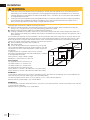
For ease of accessibility, an optional remote wall switch or millivolt thermostat may be installed in a convenient
location. Route a 2 strand, solid core millivolt wire from the valve to the wall switch or millivolt thermostat. The
recommended maximum lead length depends on wire size:
WIRE SIZE MAX. LENGTH
14 gauge (1.8mm) 100 feet (30.5m)
16 gauge (1.5mm) 60 feet (18.3m)
18 gauge (1.2mm) 40 feet (12.2m)
Disconnect the existing wires from terminals 1 and 3 (from the
ON/OFF switch) and replace with the leads from the wall switch / millivolt thermostat.
ADD IMAGE
HERE
3
1
2

EN
W415-1966 / 07.08.19
13
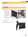
A. Lift the top casting off the
appliance.
B. Loosen the securing bolts
on the cast front off of each
of the respective retainer
brackets (located at either
side on the top). Lift the
front casting off and place
the cast front face down on
a protective surface such as a
carpet or blanket to avoid
scratching the fi nished
surface.
C. To re-install the front, repeat
in reverse order and ensure
bottom locating tabs engage
on either leg.
SCREEN
SECURING BOLTS
CAST FRONT
SECURING BOLTS
BOTTOM
LOCATING TABS
TOP
FRONT
RETAINER
5.0 fi nishing
5.1 cast front removal
• Risk of fi re!
• Never obstruct the front opening of the appliance.
• Do not strike, slam, or scratch glass. Do not operate appliance with glass removed, cracked, broken, or
scratched.
!
WARNING
• Front / screen must be in place while appliance is in operation.
!
WARNING
Remove the backing of the logo supplied and centre over the
logo installation holes, as indicated.
LOGO
5.2 logo placement

W415-1966 / 07.08.19
EN
14
fi nishing
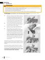
5.3 log placement
PHAZER
TM
logs glow when exposed to direct fl ame and provide a unique and realistic glowing effect. Use only
certifi ed PHAZER
TM
logs available from your local authorized dealer / distributor.
A. Place log #1 onto the burner, centering it onto the
burner tray and pushing it as close to the rear wall
of the fi rebox as possible. Move logs #2 and #3
into position, lining up the studs located on the
burner with the holes on the bottom of the logs. Sit
the notch at the bottom of log #4 against the left
outermost grate post and position the top of the
log into the pocket provided on the rear log (#1).
B. The notch in log #5 should be pressed down onto
the skewering pin located at the end of the grate
as shown to prevent it from rocking.
C. Position the notch located in log #6 against the
grate post and rest it within the notch in log #4.
D. Place the bottom of log #7 against the right
outermost grate post and the top into the pocket
provided on the center log (#6). Bend up the tab in
the log support to cradle log #7. Tear the glowing
embers into pieces and place onto the front of the
burner. Care should be taken to shred the embers
into thin, small irregular pieces as only the exposed
edges of the fi bre hairs will glow when exposed to
direct fl ame; however care should be taken to not
block the burner ports. Blocked ports can cause
an incorrect fl ame pattern, carbon deposits and
delayed ignition.
Replacement loose material must be purchased from the
original room appliance manufacturer. Application of excess
loose material may adversely affect the performance of the
appliance.
Log colours may vary. During the initial use of the appli-
ance, the colours will become more uniform as colour pig-
ments burn in during the heat activated curing process.
POSITIONING THE LOGS IMPROPERLY WILL CAUSE
FLAME IMPINGEMENT AND CARBONING.
1
4
2
3
5
6
7
• Failure to position the logs in accordance with these diagrams or failure to use only logs specifi cally approved
with this appliance may result in property damage or personal injury.
• Logs must be placed in their exact location in the appliance. Do not modify the proper log positions, since appli-
ance may not function properly and delayed ignition may occur.
• Logs are fragile and should be handled with care.
• Blocked burner ports can cause an incorrect fl ame pattern, carbon deposits, and delayed ignition.
!
WARNING

EN
W415-1966 / 07.08.19
15
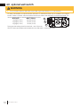
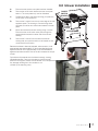
A. Ensure that the access cover plate has been installed.
B. Remove the on/off switch bracket and the cover plate
below it. The cover plate may now be discarded.
C. Decide which side of the blower housing you prefer the
on/off switch to be located on.
D. Remove the 2 screws from the top outer edge of the rear
appliance panel. The housing is mounted using these
two holes, as well as two other holes located in the rear
panel.
E. Mount and secure the blower housing using 4 screws.
Ensure that the on/off switch wires pass through the
appropriate slot located on either side of the blower
housing.
F. Remove the 2 screws from the side of the blower
housing that you want the switch to be located on and
re-secure the on/off switch.
Because the blower is thermally activated, when turned on, it will
automatically start approximately 15-30 minutes after lighting the
appliance and will run for approximately 30-45 minutes after the
appliance has been turned off. Use of the fan increases the output
of heat.
Drywall dust will penetrate into the blower bearings, causing
irreparable damage. Care must be taken to prevent drywall
dust from coming into contact with the blower or its compartment.
Any damage resulting from this condition is not
covered by the warranty policy.
SLOT
REMOVED SCREWS
6.0 blower installation
ACCESS PLATE
COVER
PLATE
ON/OFF
SWITCH
BRACKET

W415-1966 / 07.08.19
EN
16
blower installation
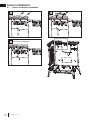
6.1 switch and bracket installation
1
3
CONNECT THE TWO WIRES TO
THE SWITCH TERMINALS.
2

EN
W415-1966 / 07.08.19
17
7.0 operation
!
WARNING
• Do not turn on if children or other at risk individuals are near the appliance.
• This appliance is equipped with a pilot which must be lit by hand while following these instructions exactly.
• Before operating, smell all around the appliance area for gas and next to the fl oor because some gas is heavier
than air and will settle on the fl oor.
• Use only your hand to turn the gas control knob. Never use tools. If the knob will not turn by hand, do not try
to repair it. Call a qualifi ed service technician. Force or attempted repair may result in a fi re or explosion.
• Do not use this appliance if any part has been under water. Immediately call a qualifi ed service technician
to inspect the appliance and replace any part of the control system and any gas control which has been
underwater.
FOR YOUR SAFETY READ BEFORE LIGHTING
WHAT TO DO IF YOU SMELL GAS
LIGHTING INSTRUCTIONS
TO TURN OFF GAS
A. Stop! Read the above safety information on this label.
B. Remove batteries from the transmitter and set thermostat to lowest setting, if equipped.
C. Turn off all electrical power to the appliance.
D. Open the glass door, if equipped.
E. Turn the gas knob clockwise to the “OFF” position.
F. Wait fi ve (5) minutes to clear out any gas. If you smell gas including near the fl oor, STOP!
Follow the instructions above in the “WHAT TO DO IF YOU SMELL GAS” section. If you
don’t smell gas; close the glass door and go to the next step.
G. If the appliance is equipped with fl ame adjustment valve turn clockwise to “OFF”.
H. Turn gas knob counter-clockwise to the “PILOT” position. (If the appliance is equipped
with an “ON/OFF” switch, ensure it is in the “ON” position.
I. Depress and hold gas knob while lighting the pilot with the push button ignitor. Keep knob
fully depressed for one minute, then release. If pilot does not continue to burn, repeat steps
E through I.
J. With pilot lit, turn gas knob counter-clockwise to the “ON” position.
K. If equipped with the fl ame adjustment valve, push and turn the knob to high.
L. Turn on all electrical power to the appliance and re-install the batteries into the transmitter, if
equipped. Set thermostat to desired setting, if equipped.
A. Set thermostat to desired setting, if equipped.
B. Turn off all electrical power to the appliance if service is to be performed.
C. Push in gas knob slightly and turn clockwise to the “OFF” position. Do not force.
• Turn off all gas to the appliance.
• Open windows.
• Do not try to light any appliance.
• Do not touch any electric switch; do not use
any phone in your building
• Immediately call your gas supplier from a
neighbour’s phone. Follow the gas supplier’s
instructions.
• If you cannot reach your gas supplier, call
the fi re department.
• If you do not follow these instructions exactly, a fi re or explosion may result causing property damage, personal
injury, or loss of life.
• If applicable, always light the pilot whether for the fi rst time or if the gas supply has run out with the glass door
opened or removed.
add gas knob
add gas valve
Ensure that a continuous gas fl ow is at the burner before installing the door. When lit for the fi rst time, the appliance
will emit an odor for a few hours. This is a normal temporary condition caused by the “burn-in” of paints and
lubricants used in the manufacturing process and will not occur again. After extended periods of non-operation
such as following a vacation or a warm weather season, the appliance may emit a slight odor for a few hours. This
is caused by dust particles in the heat exchanger burning off. In both cases, open a window to suffi ciently ventilate
the room.
For vent free appliances ONLY: if the appliance shuts off, do not relight until you provide fresh air. If appliance
keeps shutting off, have it serviced. Keep burner and control compartment clean.
note:
When lighting and re-lighting, the gas knob cannot be turned from pilot to off unless the knob is
depressed.

W415-1966 / 07.08.19
EN
18
AIR SHUTTER OPENINGS
NG 5/16” (0.31mm)
P 5/16” (0.31mm)
8.0 adjustment
8.1 venturi adjustment
8.2 fl ame characteristics
!
WARNING
• Carbon can be distributed in surrounding living area if the air shutter is improperly adjusted.
This appliance has an air shutter that has been factory set open according to
the chart below:
Regardless of venturi orientation, closing the air shutter will cause a more
yellow flame, but can lead to carbonization. Opening the air shutter will cause
a more blue flame, but can cause flame lifting from the burner ports. The flame
may not appear yellow immediately; allow 15 to 30 minutes for the final flame
colour to be established.
AIR SHUTTER ADJUSTMENT MUST ONLY BE DONE BY A QUALIFIED
INSTALLER.
AIR
SHUTTER
OPENING
VENTURI
BURNER
ORIFICE
It is important that the orifice is securely inserted into the venturi.
note:
It’s important to periodically perform a visual check of
the pilot and burner flames. Compare them to the
illustration provided. If any flames appear abnormal,
call a service person.

EN
W415-1966 / 07.08.19
19
9.0 maintenance
9.1 oxygen depletion sensor pilot cleaning
!
WARNING
• Turn off the gas and electrical power before servicing the appliance.
• Appliance may be hot. Do not service until appliance has cooled.
• Do not use abrasive cleaners on glass.
• Do not paint the pilot assembly.
This appliance and its venting system should be inspected before use and at least annually by a qualifi ed
service person. The following suggested checks should be performed by a qualifi ed technician. The appliance
area must be kept clear and free of combustible materials, gasoline, or other fl ammable vapors and liquids.
The fl ow of combustion and ventilation air must not be obstructed.
1. In order to properly clean the burner and pilot assembly, remove the logs, rocks and/or glass to ex-
pose both assemblies.
2. Keep the control compartment, media, burner, air shutter opening and the area surrounding the appli-
ance clean by vacuuming or brushing, at least once a year.
3. Check to see that all burner ports are burning. Clean out any of the ports which may not be burning
or are not burning properly.
4. Check to see that the pilot fl ame is large enough to engulf the fl ame sensor and/or thermocouple /
thermopile as well as it reaches the burner.
5. If your appliance is equipped with a safety barrier, cleaning may be necessary due to excessive lint /
dust from carpeting, pets, etc. simply vacuum using the brush attachment.
6. If your appliance is equipped with relief doors, ensure the system performs effectively. Check that the
gasket is not worn or damaged. Replace if necessary.
7. Replace the cleaned logs, rocks or glass. Failure to properly position the media may cause carboning
which can be distributed in the surrounding living area, inside the fi rebox and on exterior surfaces sur-
rounding vent termination.
8. Check to see that the main burner ignites completely on all ports when turned on. A 5 to 10 second
total light-up period is satisfactory. If ignition takes longer, consult your local authorized dealer / dis-
tributor.
9. Visually inspect the appliance for carbon build up. Using a small whisk or brush, brush off the carbon
and vacuum up or sweep into garbage.
10. This step is not applicable for Vent Free appliances: Check to see that the appliance is vent-
ing correctly. Ensure chimney system is safe and unobstructed. (If for any reason the vent air intake
system is disassembled, re-install and re-seal per the instructions provided for the initial installation).
Caution: Label all wires prior to disconnection when servicing controls. Wiring errors can cause improper and
dangerous operation. Verify proper operation after servicing.
note:
This procedure must be performed by a qualified
service person!
Inspect the pilot for any visible contamination or
debris (usually lint, pet hair, spider webs, carpet
fibre, etc.) and remove.
Disconnect the pilot from the pilot tubing line,
using the appropriate wrench. Blow out the
housing in the same direction as the gas flow.
Re-install the pilot tube, turn on the gas and
check for leaks.
If this does not improve the performance, replace
the ODS with an exact replacement. The device is
tamper resistant with no field serviceable parts.
CORRECT PILOT FLAME
Flame contacts thermocouple
correctly (clean, stable and
pronounced blue flame).
INCORRECT PILOT FLAME
Flame lifts off thermocouple
(flame becomes unstable with
more of an orange tip).
ADD IMAGE
HERE

W415-1966 / 07.08.19
EN
20
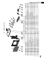
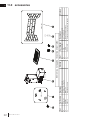
10.0 replacement parts
!
WARNING
• Failure to position the parts in accordance with this manual or failure to use only parts specifi cally approved
with this appliance may result in property damage or personal injury.
Contact your dealer for questions concerning prices and policies on replacement parts. Normally, all parts can
be ordered through your Authorized dealer / distributor.
For warranty replacement parts, a photocopy of the original invoice will be required to honour the
claim.
When ordering replacement parts always give the following information:
• Model & Serial Number of appliance
• Installation date of appliance
• Part number
• Description of part
• Finish
Parts, part numbers, and availability are subject to change without notice.
Parts identifi ed as stocked will be delivered within 2 to 5 business days for most delivery
destinations.
Parts not identifi ed as stocked will be delivered within a 2 to 4 week period, for most cases.
Parts identifi ed as ‘SO’ are special order and can take up to 90 days for delivery.
Page is loading ...
Page is loading ...
Page is loading ...
Page is loading ...
Page is loading ...
Page is loading ...
Page is loading ...
Page is loading ...
-
 1
1
-
 2
2
-
 3
3
-
 4
4
-
 5
5
-
 6
6
-
 7
7
-
 8
8
-
 9
9
-
 10
10
-
 11
11
-
 12
12
-
 13
13
-
 14
14
-
 15
15
-
 16
16
-
 17
17
-
 18
18
-
 19
19
-
 20
20
-
 21
21
-
 22
22
-
 23
23
-
 24
24
-
 25
25
-
 26
26
-
 27
27
-
 28
28


Ask a question and I''ll find the answer in the document
Finding information in a document is now easier with AI
Related papers
-
NAPOLEON GPFP Owner's manual
-
-
-
-
NAPOLEON B35NT User manual
-
-
-
-
Napoleon Fireplaces Arlington GVFS20P User manual
-
Other documents
-
Teamson Home 9378FP User manual
-
Napoleon Grills GPFP User manual
-
Continental Fireplaces CB36NTR Owner's manual
-
LG LFXS24623S LG Measure First Refrigerator Guide
-
-
-
 Martin Fireplaces VFCS20SPV User manual
-
-
Empire Comfort Systems DV-210-7SG User manual
-
Continental CVF36N User manual
