
User's Manual
LTO
RR
Www.altoproaudio.com
Version 1.0 July 2003
English English
8-CHANNEL MIXING CONSOLE
WITH DIGITAL EFFECTS
L-8

1
SAFETY RELATED SYMBOLS
CAUTION
RISK OF ELECTRIC SHOCK
DO NOT OPEN
Protective Grounding
Make sure to connect the protective grounding to prevent any
electric shock before turning ON the apparatus.
Never cut off the internal or external protective grounding wire
or disconnect the wiring of protective grounding terminal.
The symbol is used to indicate that some hazard-
ous live terminals are involved within this apparatus,
even under the normal operating conditions.
The symbol is used in the service documentation
to indicate that a specific component shall be only
replaced by the component specified in that docu-
mentation for safety reasons.
Protective grounding terminal.
Alternating current /voltage.
Hazardous live terminal.
ON: Denotes the apparatus is turned on.
OFF: Denotes the apparatus is turned off, because it uses
the single pole switch, be sure to unplug the AC power to
prevent any electric shock before you proceed with your
service.
WARNING: Describes precautions that should be
observed to prevent the danger of injury or death to
the user.
CAUTION: Describes precautions that should be
observed to prevent danger of the apparatus.
WARNING
Power Supply
Ensures the source voltage matches the voltage of the
power supply before turning ON the apparatus.
Unplug this apparatus during lightning storms or when
unused for long periods of time.
External Connection
The external wiring connected to the output hazardous live
terminals requires installation by an instructed person, or the
use of ready-made leads or cords.
Do not Remove any Cover
There are maybe some areas with high voltages inside,
to reduce the risk of electric shock, do not remove any
cover if the power supply is connected.
The cover should be removed by qualified personnel
only.
No user serviceable parts inside.
Fuse
To prevent a fire, make sure to use fuses with specified stan-
dard (current, voltage, type). Do not use a different fuse or
short circuit the fuse holder.
Before replacing the fuse, turn OFF the apparatus and dis-
connect the power source.
Operating Conditions
This apparatus shall not be exposed to dripping or spl-
ashing and that no objects filled with liquids, such as
vases, shall be placed on this apparatus.
To reduce the risk of fire or electric shock, do not expose
this apparatus to rain or moisture.
Do not use this apparatus near water.
Install in accordance with the manufacturer's instructions.
Do not install near any heat sources such as radiators,
heat registers, stoves, or other apparatus (including amp-
lifiers) that produce heat.
Do not block any ventilation openings.
No naked flame sources, such as lighted candles, should
be placed on the apparatus.
IMPORTANT SAFETY INSTRUCTIONS
Read these instructions.
Heed all warnings.
Follow all instructions.
Keep these instructions.
Only use attachments/accessories specified by the manu-
facturer.
Power Cord and Plug
Do not defeat the safety purpose of the polarized or
grounding type plug. A polarized plug has two blades
with one wider than the other. A grounding type plug
has two blades and a third grounding prong. The wide
blade or the third prong are provided for your safety.
If the provided plug does not fit into your outlet, consult
an electrician for replacement of the obsolete outlet.
Protect the power cord from being walked on or pinched
particularly at the plug, convenience receptacles, and
the point where they exit from the apparatus.
Cleaning
When the apparatus needs a cleaning, you can blow off
dust from the apparatus with a blower or clean with a rag
etc. Don't use solvents such as benzol, alcohol, or other
fluids with very strong volatility and flammability for cleaning
the apparatus body.
Clean only with a dry cloth.
Servicing
Refer all servicing to qualified personnel. To reduce the
risk of electric shock, do not perform any servicing other
than that contained in the operating instructions unless
you are qualified to do so.
Servicing is required when the apparatus has been dam-
aged in any way, such as the power supply cord or plug
is damaged, liquid has been spilled or objects have fallen
into the apparatus, the apparatus has been exposed to
rain or moisture, does not operate normally, or has been
dropped.

2
Thank you very much
LTO AUDIO TEAM
PREFACE
Dear Customer:
Thanks for choosing LTO L-8 8-Channel Mixing Console With Digital Effects and thanks for choosing one of the results
of LTO AUDIO TEAM's work and researches.
For our LTO AUDIO TEAM, music and sound more than a job... are first of all passion and let us say... our obsession!
We have been designing professional audio products for a long time in cooperation with some of the major brands
in the world in the audio field.
The LTO line presents unparalleled analogue and digital products made by Musicians for Musicians in our R&D cen-
ters in Italy, Netherlands, United Kingdom and a large range of state of the art algorithms which have been developed
by our Software Team for the last 7 years.
Because we are convinced you are the most important member of LTO AUDIO TEAM and the one confirming the quality
of our job, we like to share with you our work and our dreams paying attention to your suggestions and your comments.
Following this idea we create our products and we will create the new ones! From our side, we guarantee you and we
will guarantee you also in future the best quality, the best fruits of our continuous researches and the best prices.
Our LTO L-8 8-Channel Mixing Console with Digital Effects has 5 mono (these are provided with Ultra Low Noise micro-
phone preamplifiers and Phantom Power at +48 Volt) and 2 stereo input channels, and each of them is provided with a 3
bands graphic equaliser for HI, MID and LOW controls. It is specifically designed for professional appliance. To our surprise,
it provides 24 bit digital effect processor with 256 presets and small and exquisite modeling. Seeing is believing, let's meet
the LTO L-8.
Nothing else to add, but we would like to thank all the people that made the LTO L-8 8-Channel Mixing Console with
Digital Effects a reality available to our customers, and thank our designers and all the LTO staff, people who make
possible the realization of products containing our idea of music and sound and are ready to s upport you, our customers,
in the best way, conscious that you are our most important member.

3
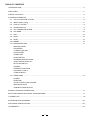
TABLE OF CONTENTS
1.INTRODUCTION...................................................................................................................................................4
2.FEATURES...........................................................................................................................................................5
3.READY TO START?...............................................................................................................................................6
4.CONTROL ELEMENTS.......................................................................................................................................7
4.1 The mono MIC/LINE channels.....................................................................................................................8
4.2 INPUT LEVEL setting...................................................................................................................................8
4.3 LOW-CUT FILTER........................................................................................................................................8
4.4 STEREO INPUTS........................................................................................................................................9
4.5 The 3 BANDS EQUALISER..........................................................................................................................9
4.6 AUX SEND..................................................................................................................................................10
4.7 PAN............................................................................................................................................................10
4.8 PEAK..........................................................................................................................................................10
4.9 LEVEL.........................................................................................................................................................10
4.10 INSERT.......................................................................................................................................................10
4.11 MASTER SECTION ...................................................................................................................................11
-MAIN MIX LEVEL
-LED METER
-2 TRACK signal path
-AUX RETURN
-POWER LED
-PHANTOM LED
-PHONES/CONTROL ROOM
-24 BIT DIGITAL EFFECTS
-DFX FOOTSWITCH
-PHONES
-STEREO AUX RETURN
-AUX SEND 1 AND 2
-2-TRACK IN/OUT
4.12 REAR PANEL .............................................................................................................................................13
-POWER
-PHANTOM
-AC INLET WITH FUSE HOLDER
-MAIN MIX OUTPUT
-CONTROL ROOM OUTPUT
5.INSTALLATION AND CONNECTION.....................................................................................................................14
6.FOR THE EXPERTS WHO WANT TO KNOW MORE..........................................................................................17
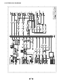
8.SYSTEM BLOCK DIAGRAMS.............................................................................................................................25
9.TECHNICAL SPECIFICATION..............................................................................................................................26
10.WARRANTY.........................................................................................................................................................28
7. PRESET LIST........................................................................................................................................................18

4
Thank you very much for expressing your confidence in products by purchasing L-8 8 Channel Mixing LTO LTO
Console with Digital Effects. The L-8 8 Channel Mixing Console with Digital Effects is professional compact mixer.
You will get the smooth, accurate more natural and open sound from this apparatus, it is really ideal for small gigs,
recording and fixed PA installations.
The L-8 8 Channel Mixing Console with Digital Effects is packed with feature that can not be found in other consoles
of its size: 5 mono (these are provided with Ultra Low Noise microphone preamplifiers and Phantom Power at +48 Volt)
and 2 stereo input channels, and each of them is provided with a 3 bands graphic equaliser for HI, MID and LOW
controls; 24 bit effects processor; 16 presets 16 variations = 256 effects; 2 AUX sends, separate level control on
each channel; highly accurate 12-segment bar graph meters and ultra low noise discrete MIC pre-amps with +48V
Phantom power and 2-Track inputs assignable to main mix, control room / headphone outputs.
1. INTRODUCTION
Your L-8 is very easy to operate but we advise you to go through each Section of this Manual carefully. In this way
you will get the best out of your L-8.

5
2. FEATURES
The L-8 8 Channel Mixing Console with Digital Effects is designed for professional appliance. It will provide the following
features:
5 MIC input channels with gold plated XLRs and balanced LINE input
2 stereo input channels with balanced TRS jacks
Ultra-low noise discrete MIC pre-amps with +48V Phantom power
Extremely high headroom offering more dynamic range
Balanced inputs for highest signal integrity
Warm, natural 3-band EQ on each channel
24 bit digital effects processor
16 presets 16 variations = 256 effects
Effect on/off by means of MUTE switch or a footswitch connected to the DFX FOOTSWITCH
Switch-able Low-cut filter on each mono channel
Peak LED on each channel
AUX send 2 switch-able to PRE/POST fader
AUX send 1/2 per channel for external effects and monitoring
Control room and headphone outputs
2-Track inputs assignable to main mix, control room / headphone outputs
Highly accurate 12-segment bar graph meters
Inserts on MIC channels

6
3. READY TO START?
3.1 Please check the AC Voltage available in your Country before connecting your L-8 to the AC socket.
3.2 Be sure that the main power switch is turned off before connecting the Mixer to the AC socket. Also, you should
make sure that all Input and Output Controls are turned down. This will avoid damages to your speakers and avoid
excessive noise.
3.3 Before turning on the L-8 you shall connect it to a power amplifier and turn-on the mixer BEFORE the power amplifier.
Once you have finished your working session you shall turn the mixer off AFTER the power amplifier.
3.4 Before disconnecting the L-8 always turn-off the Power switch.
3.5 Do not use coke, beer or solvents to clean your L-8. A dry and clean cloth will be OK.

7
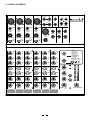
4. CONTROL ELEMENTS
7/8
2
3
4 5/6
1
MIC 1
MIC 2 MIC 3 MIC 4
BAL OR
UNBAL
BAL OR
UNBAL
BAL OR
UNBAL
BAL OR
UNBAL
LOW CUT
75Hz
18dB/Oct
LOW CUT
75Hz
18dB/Oct
LOW CUT
75Hz
18dB/Oct
LOW CUT
75Hz
18dB/Oct
1
2
LEFT (MONO)
RIGHT RIGHT
STEREO AUX RETURN AUX SEND
2-TRACK IN/OUT
TAPE IN TAPE OUT
LINE IN 5/6 LINE IN 7/8
LEFT
RIGHT
MIC (MONO)
L
R
PHONES
1
2
LEFT(MONO)
RIGHT
+15dB -45dB LINE
0dB 60dB MIC
+15dB -45dB LINE
0dB 60dB MIC
+15dB -45dB LINE
0dB 60dB MIC
+15dB -45dB LINE
0dB 60dB MIC
LINE IN 4
0dB 60dB MIC
TRIM
DFX
FOOTSWITCH
- +15
8
MAIN MIX LEVEL
PHANTOM
POWER
2TK TO
MIX
AUX RTN 1
AUX RTN 2
(DFX)
MAX
PHONES /
AUX2/DFX TO AUX 1
14. REVERB + DELAY
16. REVERB + CHORUS
15. REVERB + FLANGER
5. LARGE ROOM
13. CHORUS
12. FLANGER
11. STEREO DELAY
10. MONO DELAY
9. SPRING REVERB
8. TAPE REVERB
7. PLATE
6. SMALL ROOM
4. SMALL HALL
3. LARGE HALL
2. VOCAL 2
1. VOCAL 1
DFX MUTE
8-CHANNEL MIXING CONSOLE
L-8
LTO
RR
WITH DIGITAL EFFECTS
CONTROL
ROOM
+15+15-15-15
80Hz
LOW
0
+15+15-15-15
0
EQ
HI
12kHz
+12-12
0
2.5kHz
(PRE)
POST
AUX
0
0
- +15
8
- +15
8
1
2
/
D
F
X
PAN
RIGHT
LEFT
0
- +15
8
PEAK
LEVEL
+15+15-15-15
80Hz
LOW
0
+15+15-15-15
0
EQ
HI
12kHz
+12-12
0
2.5kHz
(PRE)
POST
AUX
0
0
- +15
8
- +15
8
1
2
/
D
F
X
PAN
RIGHT
LEFT
0
- +15
8
PEAK
LEVEL
+15+15-15-15
80Hz
LOW
0
+15+15-15-15
0
EQ
HI
12kHz
+12-12
0
2.5kHz
(PRE)
POST
AUX
0
0
- +15
8
- +15
8
1
2
/
D
F
X
PAN
RIGHT
LEFT
0
- +15
8
PEAK
LEVEL
+15+15-15-15
80Hz
LOW
0
+15+15-15-15
0
EQ
HI
12kHz
+12-12
0
2.5kHz
(PRE)
POST
AUX
0
0
- +15
8
- +15
8
1
2
/
D
F
X
PAN
RIGHT
LEFT
0
- +15
8
PEAK
LEVEL
+15+15-15-15
80Hz
LOW
0
+15+15-15-15
0
EQ
HI
12kHz
+12-12
0
2.5kHz
(PRE)
POST
AUX
0
0
- +15
8
- +15
8
1
2
/
D
F
X
BAL
RIGHT
LEFT
0
- +15
8
PEAK
LEVEL
+15+15-15-15
80Hz
LOW
0
+15+15-15-15
0
EQ
HI
12kHz
+12-12
0
MID MID MID MID MID MID
2.5kHz
(PRE)
POST
AUX
0
0
- +15
8
- +15
8
1
2
/
D
F
X
BAL
RIGHT
LEFT
0
- +15
8
PEAK
LEVEL
PRESETS
10
8
9
1
12
11
7
4
5
6
3
2
13
14
15
16
10
8
9
1
12
11
7
4
5
6
3
2
13
14
15
16
VARIATIONS
OUTPUT
-2
-4
-10
-20
-7
L R
-30
10
CLIP
2
4
7
0
LEVEL
0
- +15
8
0
- +15
8
0
- +15
8
-
8
0
PEAK
TRIM
LINE IN 3
TRIM
LINE IN 2
TRIM
LINE IN 1
TRIM
2TK TO
CTRL ROOM
PRE PRE PRE PRE PRE PRE
LEFT (MONO)
12
3
12
3
12
3
12
3
12
3

8
4
POWER
ON
OFF
PHANTOM
1
2
3
MIC 1
BAL OR
UNBAL
LOW CUT
75Hz
18dB/Oct
+15dB -45dB LINE
0dB 60dB MIC
LINE IN 1
TRIM
12
3
1
2
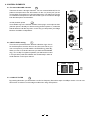
4. CONTROL ELEMENTS
4.1 The mono MIC/LINE channels
4
4.2 INPUT LEVEL setting
This Control is provided with 2 different indication rings: One is
for the Microphone and the other for the Line levels. When you
use a microphone you shall read the OUTSIDE ring (0-60 dB),
When you use a Line level instrument you shall read the INSIDE
ring (+15~-45 dB). For optimum operation you shall set this control
in a way that the peak LED will blink also occasionally in order to
avoid distortion on the input channel.
These are Channel 1 through Channel 4. You can connect balanced, low im-
pedance microphones to the XLR socket. On the 1/4" phone jack you can
connect either a microphone or a line level instrument. You shall never connect
an unbalanced microphone to the XLR socket if you do not want to damage
both the Microphone and the Mixer.
48 Volt phantom power
It is available only to the XLR Mic sockets. Never plug in a microphone when
phantom power is already on. Before turning phantom power on, make sure
that all faders are all the way down. In this way you will protect your Stage
Monitors and Main Loudspeakers.
3
4.3 LOW-CUT FILTER
By pressing this button you will activate a 75 Hz low frequency filter with a slope of 18 dB per octave. You can use
this function to reduce hum and stage rumble when using microphones.

9
5
6
7
8
LEFT (MONO)
RIGHT RIGHT
LINE IN 5/6 LINE IN 7/8
MIC (MONO)
0dB 60dB MIC
TRIM
LEFT (MONO)
12
3
5
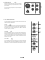
4.4 STEREO INPUTS
These are Channel 5 through 8. They are organised
in stereo pair and they are provided with 1/4" TRS
phone sockets.
If you connect only the left jack, the input will operate
in mono mode.
4.5 The 3 BANDS EQUALISER
A 3-band equaliser is provided for all input channels with a wide
range of frequency adjustment.
6
4.5.1 HI
This is the Treble control. You can use it to get rid of high frequency
noises or to boost the sound of cymbals or the high harmonics of
the human voice. The gain range goes from -15dB to +15dB with
a center frequency of 12 kHz.
7
4.5.2 MID
This is the Midrange control. It can affect most fundamental fre-
quencies of all musical instruments and human voice. An attentive
use of this control will give you any very wide panorama of sound
effects. The gain range goes from -12dB to +12dB and the center
frequency is 2.5 kHz.
8
4.5.3 LOW
This is the Bass control. Boost male voice or kickdrum and bass
guitar. Your system will sound much bigger than what it is. The gain
range goes from -15dB to +15dB and the center frequency is 80 Hz.
+15+15-15-15
80Hz
LOW
0
+15+15-15-15
0
EQ
HI
12kHz
+12-12
0
2.5kHz
(PRE)
POST
AUX
0
0
- +15
8
- +15
8
1
2
/
D
F
X
PAN
RIGHT
LEFT
0
- +15
8
PEAK
LEVEL
MID
PRE

10
9
10
11
12
13
CHANNEL INSERT
(P -FADER/PRE-EQ TIP SEND/RING RETURN)RE
CH4 CH3 CH2 CH1
9
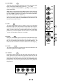
4.6 AUX SEND
These two controls are used to adjust the level of the signal sent to AUX
buses, and their adjustable range goes from - to +15dB.
AUX1 is configured as PRE-FADER, so, generally, it can be used for
monitor application.
While AUX2 is configured as POST-FADER, therefore, most of the times,
it will be used for effects and processors input, but, you can also changed
it to PRE-FADER configuration according to the specific application.
(For more detail, please see chapter 6.)
In this typical compact unit, excluding sending out directly to the external
effect or processor equipment, AUX SEND2 will also be sent to the
internal onboard effect module.
10
4.7 PAN
This is the PANORAMA control, or balance control. You can adjust
the stereo image of the signal via this Control. Keep this control in
center position and your signal will be positioned in the middle of
stage. Turn this control fully counterclockwise and the signal will be
present only on the left speaker and vice-versa. Of course a wide
number of intermediate positions is available.
11
4.8 PEAK
Inside your L-8 the audio sign al is monitored in several different stages
and then sent to the PEAK Led. When this Led blinks, it warns you
that you are reaching signal saturation and possible distortion. The
PEAK Led will blink with a level that is 6dB before actual clipping.
12
4.9 LEVEL
This Control will adjust the overall level of this channel and set the
amount of signal sent to the Main output.
13
4.10 INSERT
Insert points are provided for the Mono Mic Channels. When you
insert a jack in the insert socket, the signal will be taken out after the
Input Gain Control (Trim), sent to an external processor such a com-
pressor-limiter, and returned into the channel strip immediately before
the EQ section. Of course, the jacks used must be stereo (Tip Send/
Ring Return).
+15+15-15-15
80Hz
LOW
0
+15+15-15-15
0
EQ
HI
12kHz
+12-12
0
2.5kHz
(PRE)
POST
AUX
0
0
- +15
8
- +15
8
1
2
/
D
F
X
PAN
RIGHT
LEFT
0
- +15
8
PEAK
LEVEL
MID
PRE

- +15
8
MAIN MIX LEVEL
PHANTOM
POWER
2TK TO
MIX
AUX RTN 1
AUX RTN 2
(DFX)
MAX
PHONES /
AUX2/DFX TO AUX 1
CONTROL
ROOM
OUTPUT
-2
-4
-10
-20
-7
L R
-30
10
CLIP
2
4
7
0
LEVEL
0
- +15
8
0
- +15
8
0
- +15
8
-
8
0
2TK TO
CTRL ROOM
14
15
16
17
18
19 20
21
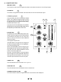
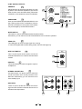
- POWER LED
This LED indicates when the Power is on in your L-8.
19
- PHANTOM LED
This LED indicates when the Phantom Power is switched on.
20
This Control sets the amount of signal sent to the Control Room and headphone.
- PHONES/CONTROL ROOM
21
4.11 MASTER SECTION
15
- LED METER
This stereo 12 segments Led Meter will indicate the level of the overall output signal.
14
- MAIN MIX LEVEL
This Control set the amount of signal sent either to the Main Out socket or to the Tape Output.
16
- 2 TRACK signal path
If you push down the 2TK TO CONTROL ROOM
button, the 2 TRACK IN signal will be routed
into the Control Room output and the level will
be adjusted by the Control Room knob nearby
the Main MIX LEVEL knob.
If you push the 2TR TO MIX button the 2 TRACK
IN signal will be routed into the MAIN output and will
be adjusted by the MAIN MIX LEVEL knob.
17
- AUX RETURN
As implied in the name, the Auxiliary Returns are
used to 'return' the signal from the external effects
or processors to the main mix, but, most of the
times, it can also be worked as the additional
stereo line inputs.
In this typical compact unit:
AUX RETURN1 is configured to be assigned to
the main mix bus permanently, for mono application,
only use the left input jack.
But for AUX RETURN2, instead of assigning the
returned signal to main mix bus, it can also to AUX1
bus, and in this case, adjust AUX2/DFX TO AUX1
knob to control the input level.
Normally, AUX RETURN2 is connected rightly
with the output of the internal digital effects, but,
this signal flow will be broken, if you have any
external signal inserted from these two jacks.
11

12
22
This socket will send out the mix signal to a pair of
headphones.
27
- PHONES
14. REVERB + DELAY
16. REVERB + CHORUS
15. REVERB + FLANGER
5. LARGE ROOM
13. CHORUS
12. FLANGER
11. STEREO DELAY
10. MONO DELAY
9. SPRING REVERB
8. TAPE REVERB
7. PLATE
6. SMALL ROOM
4. SMALL HALL
3. LARGE HALL
2. VOCAL 2
1. VOCAL 1
DFX MUTE
PRESETS
10
8
9
1
12
11
7
4
5
6
3
2
13
14
15
16
10
8
9
1
12
11
7
4
5
6
3
2
13
14
15
16
VARIATIONS
PEAK
- 24 BIT DIGITAL EFFECTS
Adjust this knob to select the right effect you wish
to perform. There are total 16 options for you: seve ral
kinds of reverb, mono and stereo delay, effects with
modulation, and versatile two-effect combination.
PRESETS
22
23
Since you have selected the preferable effect, the next
step, please go with the fine consideration, there are
also total 16 variations for each preset, Each variation
may be managed by several different factors.
VARIATIONS
23
24 25
This switch is used to activate/deactivate the effect facility.
Sometimes, you can also use the DFX FOOTSWITCH for convenient operation.
MUTE SWITCH
24
This LED lights up when the input signal is too strong.
In case of the digital effect module being muted, this LED also lights up.
PEAK LED
25
PHONES
DFX
FOOTSWITCH
- DFX FOOTSWITCH
26
This 1/4" phone jack can be used to connect an
external footswitch to turn on/off the onboard effect
module.
26
27
1
2
STEREO AUX RETURN AUX SEND
2-TRACK IN/OUT
TAPE IN TAPE OUT
LEFT
RIGHT
L
R
1
2
LEFT(MONO)
RIGHT
28
29
30
Use these stereo 1/4" phone socket to return the
sound of an effect unit or sound processor to the
Main Mix. Alternatively you can use them as an
extra auxiliary input.
- STEREO AUX RETURN
28
These 1/4" phone sockets are used to send out the
signal from the AUX Bus to external devices such as
effects and sound processors.
- AUX SEND
29

13
30
- 2-TRACK IN/OUT
Use the Tape input if you wish to listen to your Mix from a Taper Recorder or DAT, You can assign the signal coming
form the Taper Recorder either to a pair of studio monitor using the Control Room assignment on the front panel or
you can also send the signal directly to the Main Mix.
Input
Output
These 1/4" TRS sockets will route the main mix into a tape recorder.
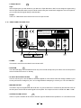
31
- POWER
This switch is used to turn the Main Power ON and OFF.
4
- PHANTOM
This switch will apply +48 Volt Phantom Power only to the 5 XLR microphone inputs. Never connect microphones
when the Phantom Power is on already.
32
- AC INLET WITH FUSE HOLDER
Use it to connect your L-8 to the Main AC with the supplied AC cord. Please check the Voltage available in your
Country and how the Voltage for your L-8 is configured before attempting to connect your L-8 to the Main AC.
This stereo output is supplied both with XLR and 1/4" jack socket and it is controlled by the Main Mix Level on
the front panel. It will send the audio signal to an amplifier. The output level can be varied from - to +15dB.
- MAIN MIX OUTPUT
33
These 1/4" phone sockets will be used to send the signal to Studio Monitor speakers or to a second set of PA.
- CONTROL ROOM OUTPUT
34
4.12 REAR PANEL DESCRIPTION
31
4
32 33
Use only with a 250V fuse
POWER
ON
OFF
PHANTOM
RATED POWER CONSUMPTION: 18W
LEFT
RIGHTRIGHT
LEFT
MAIN MIX OUTPUT
(BAL/UNBAL)
CONTROL
ROOM OUTPUT
CAUTION:
REPLACE WITH THE SAME TYPE FUSE AND RATING
DISCONNECT SUPPLY CORD BEFORE CHANGING FUSE
CAUTION
RISK OF ELECTRIC SHOCK
DO NOT OPEN
WARNING: SHOCK HAZARD - DO NOT OPEN
AVIS: RISQUE DE CHOC ELECTRIQUE - NE PAS OUVRIR
RIGHT
LEFT
Use only with a 250V fuse
Use only with a 250V fuse
12
3
12
3
AC INPUT
EUROPE
210-240V 50Hz
Fuse:T250mAL
USA / Canada
100-120V 60Hz
Fuse:T500mAL
UK / Aust
240V 50Hz
Fuse:T250mAL
34

14
Turn down all Input and Output Gain Controls.
Connect phantom powered microphones before switching on the +48Volt Phantom Power switch.
If you have a power amplifier connected to your L-8 set the Level of the amplifier at no more than 70%.
Now, set the CONTROL ROOM/PHONES level at no more than 50%. In this way you will be able to hear later
what you are doing connecting a pair of headphones or a pair of powered studio monitor speakers.
Position HI, MID and LOW eq controls on middle position.
Position panoramic (PAN) control on center position.
With a headphone or studio monitor speakers connected apply a Line Level input signal so that the PEAK Led
does not light up.
At this point increase the input gain so that the PEAK led will blink occasionally. In this way you will maintain
good headroom and ideal dynamic range.
Now connect a microphone and ask the singer to sing loud into the microphone. Turn slowly the Gain Control
clockwise and have the PEAK Led blink only occasionally.
Now repeat the same sequence for all input channels. The Main Led Meter could move up into the red section.
In this case you can adjust the overall output level through the MAIN MIX control.
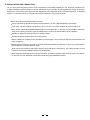
5. INSTALLATION AND CONNECTION
Ok, you have got to this point you are now in the position to successfully operate your L-8. However, we advise you
to read carefully the following section to be the real Master of your own Mix. Not paying attention enough to the Input
signal level, to the routing of the signal and the assignment of the signal will result in unwanted distortion, a corrupted
signal or no sound at all. So you should follow this procedure for every single channel:

15
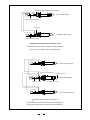
Strain Clamp
Sleeve
Tip
Ring
Sleeve=Ground/Screen
Ring=Return Signal
Tip=Send Signal
Use for Pre-Gain Channel Inserts
1/4" Stereo (TRS) Jack Plug
Strain Clamp
Sleeve
Tip
Ring
Sleeve=Ground/Screen
Ring=Right Signal
Tip=Left Signal
Use for Headphone, Stereo Return
1/4" Stereo (TRS) Jack Plug
Strain Clamp
Sleeve
Tip
Sleeve=Ground/Screen
Tip=Signal
Use for Mono Line In, Mono 1/4"Jack Plugs
1/4" Mono (TS) Jack Plug
2=Hot(+)
3=Cold(-)
1=Ground/Screen
(seen from soldering side)
Use for Balanced Mic Inputs
(For unbalanced use, connect pin 1 to 3)
3-pin XLR Male Plug
2=Hot(+)
3=Cold(-)
1=Ground/Screen
Use for Main output
(For unbalanced use, leave pin 3 unconnected)
3-pin XLR Line Socket
(seen from soldering side)
1
2
3
1
2
3
You can connect unbalanced equipment to balanced inputs and outputs. Simply follow these schematics.
5.1 SOME FINAL TIPS ON WIRING CONFIGURATION

16
Sleeve=Ground/Screen
Tip=Signal
Sleeve=Ground/Screen
Ring=Return Signal (Connected together)
To Channel Insert
To Tape or FX Input
'Tapped' Connection Direct Output Lead
(Enables the Insert to be used as a Direct Output
while maintaining the channel signal flow)
Sleeve
Sleeve=Ground/Screen
Ring=Return Signal
Tip=Send Signal
To Channel Insert
To Processor Input
To Processor Output
Ring
Tip
-Stereo lead for insert Connection
(To be used when the processor does not employ a
single jack connection for the In/Out Connections)

17
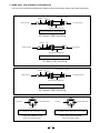
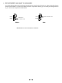
6. FOR THE EXPERTS WHO WANT TO KNOW MORE
As we have told you previously in this Manual, the Aux Send 2 Control both on Mono and on stereo channels is factory
wired as POST-FADER. If you have some skill in electronic components solder ing you can modify this setting and have
all your AUX sends configured as PRE-FADER.
Modification on mono and stereo channels
Before
Disconnect
the POST route
Aux
(PRE)
POST
After
Aux
(PRE)
POST
Solder the PRE route

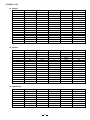
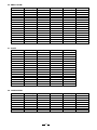
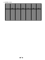
7. PRESET LIST
01. VOCAL1
No
Pre-delay
Rev Time
Room Size
Rev. Type
Hi Damp
1
84 1.00
39
Hall
-12
2
30
1.00 8
Spring
3
0 4.50 10
Plate
4
5
6
7
8
9
10
11
12
13
14
15
16
55
3.60
11
Spring
10 1.20 9
Hall
79
3.60
8
Plate
-12
-12
-12
-12
-12
-12
-12
-12
-12
-12
-12
-12
-12
-12
-12
Plate
Spring
Tape
Plate
Hall
Spring
Tape
Tape
Plate
Plate
41
41
9
41
10
45
9
10
11
0.8
1.50
2.40
0.90
1.50
1.00
1.00
2.10
4.50
1.70
45
45
25
0
45
114
40
50
45
55
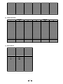
02. VOCAL2
No
Pre-delay
Rev Time
Room Size
Rev. Type
Hi Damp
1
114
45
79
10
55
0
30
84
55
45
50
40
114
45
0
25
Hall
-12
2
Spring
3
Plate
4
5
6
7
8
9
10
11
12
13
14
15
16
Spring
Hall
Plate
-12
-12
-12
-12
-12
-12
-12
-12
-12
-12
-12
-12
-12
-12
-12
Plate
Spring
Tape
Plate
Hall
Spring
Tape
Tape
Plate
1.00
0.80
3.60
1.20
3.60
4.50
1.00
1.00
1.70
4.50
2.10
1.00
1.00
1.50
0.90
2.40
10
41
8
9
11
10
8
39
11
41
9
45
10
41
41
9
Spring
03. LARGE HALL
No
Pre-delay
Rev Time
Room Size
Hi Damp
1
79
79
78
78
82
82
82
82
2
-0.96
-12.00
-0.96
-12.00
-0.96
-12.00
3
4
5
6
7
8
5.40
5.40
5.40
5.40
4.50
4.50
4.50
4.50
55
55
40
40
50
50
27
27
45
45
35
35
43
43
33
33
-0.96
-12.00
Rev level
18

82
82
82
82
88
88
88
88
9
10
11
12
13
14
15
16
4.00
4.00
4.00
4.00
3.60
3.60
3.60
3.60
50
50
27
27
45
45
23
23
42
42
32
32
41
41
30
30
-0.96
-12.00
-0.96
-12.00
-0.96
-12.00
-0.96
-12.00
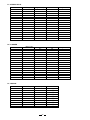
05. LARGE ROOM
No
Pre-delay
Rev Time
Room Size
Hi Damp
1
55
55
40
40
50
50
27
27
50
50
27
27
45
45
23
23
82
88
2
-0.96
-12.00
3
4
5
6
7
8
9
10
11
12
13
14
15
16
4.50
4.00
3.60
2.90
20
20
11
11
19
19
11
11
18
18
10
10
18
18
10
10
-0.96
-12.00
-0.96
-12.00
-0.96
-12.00
-0.96
-12.00
-0.96
-12.00
-0.96
-12.00
-0.96
-12.00
2.90
2.90
2.90
3.60
3.60
3.60
4.00
4.00
4.00
4.50
4.50
4.50
88
88
88
88
88
88
88
82
82
82
82
82
82
82
Rev level
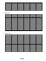
04. SMALL HALL
No
Pre-delay
Rev Time
Room Size
Hi Damp
1
45
45
23
23
40
40
20
20
40
40
20
20
40
40
20
20
92
100
2
-0.96
-12.00
3
4
5
6
7
8
9
10
11
12
13
14
15
16
2.90
2.90
2.90
2.90
2.10
2.10
2.10
2.10
1.50
1.50
1.50
1.50
1.00
1.00
1.00
1.00
39
39
28
28
38
38
27
27
37
37
26
26
36
36
25
25
-0.96
-12.00
-0.96
-12.00
-0.96
-12.00
-0.96
-12.00
-0.96
-12.00
-0.96
-12.00
-0.96
-12.00
100
100
100
100
100
100
100
100
100
100
100
92
92
92
Rev level
19
Page is loading ...
Page is loading ...
Page is loading ...
Page is loading ...
Page is loading ...
Page is loading ...
Page is loading ...
Page is loading ...
Page is loading ...
Page is loading ...
-
 1
1
-
 2
2
-
 3
3
-
 4
4
-
 5
5
-
 6
6
-
 7
7
-
 8
8
-
 9
9
-
 10
10
-
 11
11
-
 12
12
-
 13
13
-
 14
14
-
 15
15
-
 16
16
-
 17
17
-
 18
18
-
 19
19
-
 20
20
-
 21
21
-
 22
22
-
 23
23
-
 24
24
-
 25
25
-
 26
26
-
 27
27
-
 28
28
-
 29
29
-
 30
30


Ask a question and I''ll find the answer in the document
Finding information in a document is now easier with AI
Related papers
Other documents
-
Rane MLM 65 Printable Label Template
-
Humminbird AMX-220FX User manual
-
Nilfisk-ALTO PM-6 DRAGONFLY User manual
-
 Whirlwind MIX-5 User manual
-
 Audio 2000 AMX7333 Owner's manual
-
 YORKVILLE M8 Owner's manual
-
 Audio 2000 AMX7303 Owner's manual
-
Focusrite RED 6 Mic Pre and EQ User guide
-
Fiveo F62X Owner's manual
-
 Wharfedale Pro Force 12 User manual


