A qualified electrician must perform a ground continuity
check on the wall receptacle before beginning the
installation to ensure that the outlet box is properly
grounded. If not properly grounded, or if the wall
receptacle does not meet electrical requirements noted
(under ELECTRICAL REQUIREMENTS), a qualified electrician
should be employed to correct any deficiencies.
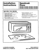
WARNING:
5LVNRI(OHFWULF6KRFN
Can cause injury or death:
5HPRYHKRXVHIXVHRU
RSHQFLUFXLWEUHDNHUEHIRUH
EHJLQQLQJLQVWDOODWLRQWRDYRLG
VHYHUHRUIDWDOVKRFNLQMXU\
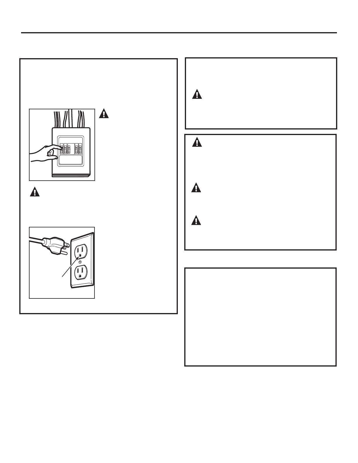
WARNING:5LVNRI(OHFWULF6KRFN
Can cause injury or death: THIS APPLIANCE MUST BE
PROPERLY GROUNDED WRDYRLGVHYHUHRUIDWDOVKRFN
120 V Models
The power cord of this
appliance is equipped with
DWKUHHSURQJJURXQGLQJ
SOXJZKLFKPDWHVZLWK
DVWDQGDUGWKUHHSURQJ
JURXQGLQJZDOOUHFHSWDFOH
to minimize the possibility
RIHOHFWULFVKRFNKD]DUG
from this appliance.
IMPORTANT SAFETY INSTRUCTIONS
3
ELECTRICAL REQUIREMENTS
Installation Instructions
Ensure proper
ground exists
before use.
CAUTION: For personal safety, the
PRXQWLQJVXUIDFHPXVWEHFDSDEOHRIVXSSRUWLQJWKH
FDELQHWORDGLQDGGLWLRQWRWKHDGGHGZHLJKWRIWKLV
²SRXQGSURGXFWSOXVDGGLWLRQDOPLFURZDYHRYHQ
ORDGVRIXSWRSRXQGVRUDWRWDOZHLJKWRI²
pounds.
CAUTION: For personal safety, this product
FDQQRWEHLQVWDOOHGLQFDELQHWDUUDQJHPHQWVVXFKDVDQ
island or a peninsula. It must be mounted to BOTH a top
FDELQHW$1'DEDFNZDOO
CAUTION:7RDYRLGWKHULVNRISHUVRQDO
LQMXU\EDFNLQMXU\RURWKHULQMXULHVGXHWRH[FHVVLYH
ZHLJKWRIWKHPLFURZDYHRUSURSHUW\GDPDJH\RXZLOO
QHHGWZRSHRSOHWRLQVWDOOWKLVPLFURZDYH
:KHUHDVWDQGDUGWZRSURQJZDOOUHFHSWDFOHLV
encountered, it must be replaced with a properly
JURXQGHGWKUHHSURQJZDOOUHFHSWDFOHLQVWDOOHGE\D
qualified electrician.
WARNING:5LVNRI(OHFWULF6KRFN
Can cause injury or death: DO NOT, under any
FLUFXPVWDQFHVFXWGHIRUPRUUHPRYHDQ\RIWKHSURQJV
from the power cord. Do not use with an extension cord.
Failure to comply may cause fire.
120 V Models
This product requires a three-prong grounded outlet.
Product rating is 120 volts AC, 60 Hertz, 15 amps, and 1.70
kilowatts. This product must be connected to a supply
circuit of the proper voltage and frequency. Wire size must
conform to the requirements of the National Electrical
Code or the prevailing local code for this kilowatt rating.
The power supply cord and plug should be brought to a
separate 15 to 20 ampere branch circuit single grounded
outlet. The outlet box should be located in the cabinet
above the microwave oven and away from any potential
microwave ducting. The outlet box and supply circuit
should be installed by a qualified electrician and conform
to the National Electrical Code or the prevailing local code.