Schartec Move 1000-Speed Installation And Operating Instructions Manual

Category
Garage Door Opener
Type
Installation And Operating Instructions Manual

This manual is also suitable for

25
PLUS
English
Installation and Operating Instructions
(Begins on Page 25)
FS 600 600N
FS 1000 1000N
FS 1200 1200N
FS 600-Speed 600N
FS 1000-Speed 1000N
S/N
CONTENTS
Important Safety Instructions...........……………………………....……………………………..27
Warranty Conditions.............................................................................................................30
Product Description & Features............................................................................................31
Pre-Installation Recommendations.......................................................................................32
Installation Instructions..........................................................................................................33
- Boom Rail Assembly
- Mounting Wall and Door Brackets
- Installation of Boom Rail and Operator
Programming Instructions....................................................................................................37
Connection of external control and accessories..................................................................40
Manual Disengagement.......................................................................................................42
Technical Specifications....………………………………………………………………….........43
Parts Listing……………………......…………….....................................................................45
Common Faults & Solutions.................................................................................................46
26
WARNING
Please read the manual carefully before you begin the installation and use. The installation of your new
garage door operator must be performed by a competent expert or a specialist company. A competent
person is, in accordance
with EN 12635, considered a person who has appropriate training, qualified
knowledge and practical experience in order to mount a door system properly and safely, and maintain.
The installation or repair without technical qualifications can cause serious injury, death and / or property
damage.
IMPORTANT SAFETY INSTRUCTIONS
1. Intended Use:
The garage door operator is designed exclusively for impulse operation of spring-balanced Sectional and
Up & Over garage doors doors in private / non-commercial operations. Door systems used in a public
area have only one protective device, e.g. the force limiter, and may only be operated under supervision.
The garage door operator is designed for operation in dry rooms.
2. Unintended Use:
The garage door operator must not be used for purposes other than for the automation of garage doors.
Continuous operation and the use in the commercial sector is not permitted. The operator must not be
used with doors without fall protection.
3. Qualifications of the fitter and installer
Proper fitting and maintenance should only be done by a competent / specialist company or a
competent / qualified person in accordance with the instructions that can ensure the safe and flawless
operation of the assembly. A competent person is, in accordance with EN 12635, considered a person
who has appropriate training, qualified knowledge and practical experience in order to mount a door
system properly and safely.
4. Safety instructions for installation, repair, maintenance, and disassembly of the door system
DANGER!
Compensation springs are under high tension.
The adjusting or loosening the compensating springs can cause serious injuries! If necessary,
maintenance and repair work must be made by a trained door system technician! Never attempt to
replace, readjust, repair, or move the balancing spring for the counterbalancing of the door or their
holders. Inspect that the entire door system (pivots, door bearings, ropes, springs and fastenings) for
wear and possible damage. Check them for signs of rust, corrosion and cracks. Error in the door system
or misaligned doors can cause severe injury! Do not use the door system if repair or adjustment work
needs to be done!
Dear Customer
Thank you for choosing a quality product from Force. Thanks to our unique quality
management system, we continuously ensure that Force operators meet the highest
standards of quality and comfort. Thank you for your confidence in purchase and we wish you
much pleasure with your new Force garage door opener.
Declaration of Conformity (CE)
The FS and PLUS series garage door openers from Force meet the requirements of the
applicable European and national guidelines. Compliance was demonstrated that
corresponding declarations, certificates, test reports and documents have been obtained by
the manufacturer and can be requested if required.
27
Mains Voltage
There is danger of electrocution upon contact with the mains voltage . Note, therefore, the following
instructions: Electrical connections may only be performed by a qualified electrician. Electrical installation
on site must comply with the relevant safety regulations (230/240 V AC, 50/60 Hz).
Disconnect the operator from the mains before performing any operator service.
WARNING!
Non-suitable fastening materials
Use of unsuitable fixing materials can result in the operator not being securely attached and can become
loosened. The supplied mounting materials must be checked for their suitability for the intended
installation location by the installer. Use the supplied mounting material (plugs) for concrete ≥ B15.
Fatal injury from hand rope
A guided type hand rope (pull cord) may lead to strangulation. Remove the pull rope/cord upon installing
the operator.
Risk of injury from unintentional door movement
Improper installation or handling of the operator can trigger unwanted door travel and can result in people
or objects being pinched resulting in serious injury or death. Follow all instructions contained in this
manual. Any incorrectly mounted control devices (such as push buttons) can unintentionally trigger door
travel resulting in persons or objects becoming pinched. Control devices must be mounted at a height of
at least 1.5 m
(away from children). Assemble fixed control devices (such as push buttons) within sight of the door but
away from moving parts.
Risk of injury due to unexpected door travel
Installation, maintenance, repair, and dismantling of the operator and the garage door must be carried out
by a specialist(s). Upon failure of the garage door operator, directly entrust an expert with the inspection
or repair.
Safety advice for mounting
The specialist must ensure that, in carrying out the installation, the applicable regulations regarding
occupational safety and those governing the operation of electrical equipment are complied with.
National guidelines must therefore be observed. Possible hazards, as defined in DIN EN 13241-1, are
prevented by the design and installation according to our specifications. The garage ceiling must be
designed so that a secure attachment of the opener system is ensured. Too high or too lightweight of
ceiling material, the opener system must be attached to additional safety/security braces.
CAUTION!
Crushing Risk by Boom Rail Mounting
When assembling the boom rail, there is a danger that fingers can be caught. Take care not to get your
fingers caught between the profile ends.
Pinching Risk in the Boom Rail
Grasping with fingers into the boom rail while the door is moving may cause pinching. Grasp only when
the door is not moving on the boom rail.
5.Safety information for commissioning and operation
CAUTION!
Pinching Risk in the Boom Rail
Grasping with fingers into the boom rail while the door is moving may cause pinching. Grasp only when
the door is not moving on the boom rail.
Risk of injury by pull cord
If you hang from the cord knob, the door can crash down and you may become injured. The operator
could become dislodged and injure people underneath, damage or even destroy objects. Do not hang
from the pull cord.
28
WARNING!
Risk of injury by rapidly closing door
If the pull cord knob is pulled while the door is open, there is a risk that the door could close quickly
because of weak, broken, or defective springs or due to faulty counterbalance mechanism. The pull
cord should only be pulled while the door is closed.
Risk of injury during door movement
While the door is moving, the risk of injury or damage to persons or objects is increased while standing
in the movement area of the door. Make sure that no children are playing with the door operator system.
Ensure that when the door is moving that no persons or objects are located within the door movement
area. Only use the garage door operator when you have view of the garage door it self and can monitor
its movement. Monitor the door travel until the door has reached the end position. Drive or pass through
the garage door entryway ONLY when the door has come to a standstill! Never stand directly under the
open door.
Proper Use
Demonstrate to all persons using the door operator system the proper and safe operation of the garage
door operator. Demonstrate and test the mechanical release as well as the safety return.
6. Precautions for the use of the remote control
WARNING!
Risk of injury from unwanted or accidental door movement
Accidental pressing of a button on the remote control can lead to unwanted door movements and injure
someone. Make sure that remote controls are not accessible to children and are only used by persons
who have been instructed in the operation of the remote-controlled garage door operator system! Only
use the remote when you are in visual contact with the door unless a safety device is connected ( e.g.
photocells). Drive or pass through the garage door entryway ONLY when the door has come to a
standstill! Never stand directly under the open door. Note that the accidentally pressing a key on the
remote (for example in your pocket / handbag) may lead to an unwanted door travel.
7. Safety Installations
Safety-related functions and components such as automatic power shutdown and the use of external
photocells have been tested and meet the requirements of EN 12453 and EN 12445 standards.
WARNING!
Risk of injury from malfunctioning safety devices
To test the safety reverse, with both hands, hold the door as it closes. The garage door operator system
must stop and initiate the safety reverse. Test this also as the garage door opens. The door system must
switch off and stop the door. Upon failure of the security reverse, directly entrust an expert with the
inspection or repair.
8. Inspection and maintenance
The garage door operator is maintenance-free. According to the manufacturer and for your own safety,
we recommend that you allow the garage door operator system to be inspected by an expert. A check or
a necessary repair should only be performed by a specialist. Please also contact your supplier. A visual
inspection may be carried out by the user. Check all safety and security features on a monthly basis.
Existing errors or defects must be rectified immediately. Inspect the tension of toothed belt every six
months and adjust accordingly if necessary. During the opening and closing phase, the belt may loll
briefly because of rail profile. However, this effect does not have any technical losses and also does not
adversely affect the function and life of the belt.
29
Warranty
We are exempt from the warranty and product liability if the unit has been modified without our prior
consent or improper installations are performed or initiated against our assembly instructions.
Furthermore, we assume no responsibility for the inadvertent or negligent operation of the operator, as
well as for the improper maintenance of the operator and accessories, nor for the improper maintenance
of the door and its counterbalance mechanism. Batteries, light bulbs, and LEDs are also excluded from
the warranty claims.
Duration of Warranty
In addition to the legal guarantee of the dealer from the purchase contract, we provide the following
warranty from date of purchase:
3 Years
2 Years on radio and accessories
The warranty time is not extended upon using the warranty. For replacement deliveries and rectification
work, the warranty period is six months or at least the remainder of the warranty period.
Conditions
The warranty applies only to the country where the product was purchased. The product must have been
purchased through our authorized distribution channels. The warranty only covers damage to the
contractual item itself. Reimbursement of expenditure for dismantling and installation, testing of
corresponding parts, as well as demands for lost profits and damages are excluded from the guarantee.
The receipt of purchase serves as proof of warranty.
Performance
For the duration of the warranty, we shall resolve any defects of the product which are demonstrably
attributable to a material or manufacturing defect. At our discretion, we shall, free of charge, replace the
defective product for a non-defective, repair or refund a diminished value. Excluded are damages
caused by:
Improper installation and connection
Improper commissioning and operation
External influences such as fire, water, abnormal weather conditions
Mechanical damage due to accidents, dropping or shock
Negligent or deliberate destruction
Normal wear and tear or poor maintenance
Repair by unqualified persons
Use of non-original parts
Removal or obscuring of the serial number
Replaced parts become property of the manufacturer
WARRANTY CONDITIONS
30
1. Automatic safety reverse
Automatic stop / automatic reverse are controlled by the software on our circuit boards. We are
cautious to protect your children, pets and property.
2. Soft start / Soft
stop
Ramping speed up and down at the start and end of each cycle reduces stress on the door and
opener, and makes for longer life and quieter operation.
3. Auto-Close
Auto-Close ensures peace of mind and keeps your house secure by automatically closing the door upon
entering or exiting the garage.
4. Self learning - open and close obstruction force
The amount of opener power for different stages of the door’s travel is learned during setup and is
constantly re-profiled. Opener force measurement is automatically adjusted to a suitable range.
5. Simple adjustment of the end positions
Setting the end positions is easily done by pressing a button on the display panel.
6. Terminals for Accessories
Terminals are available for photocells (safety beam) extra receivers, wired or wireless wall
switches, caution/warning lights and more.
7. Energy saving LED
The courtesy LED light has a 3 minute delay, switching on with each cycle to illuminate your
darkened garage.
8. Battery backup available
Our openers can be connected with our battery backup in the event of power failure at your
home.
9. Self-Lock in gear motors
Force gear motors will self-lock with our disengagement systems.
10. Manual release
Don't worry about power failure, the manual release system is a solution for operation the door
at any time.
11. Transmitter technology
Rolling Code technology (7.38 x 10¹⁹ Combinations), 433.92Mhz frequency, 4 channel remote
control design ensures that you can control 4 different motors with one transmitter.
12. Lower headroom
With as little as 30mm required between the ceiling and the highest point of the door travel, the
opener can be flush mounted for low headroom applications.
13. Metal bottom plate, stronger and more secure
14. Open/Close moving operation buttons (UP / DOWN)
15. External mains power fuse (B) (see below)
PRODUCT DESCRIPTION & FEATURES
31
B
Open (Move UP)
Close (Move DOWN)
PRE-INSTALLATION RECOMMENDATIONS
1. Check the garage door and garage door system
DANGER!
Balancing springs are under high tension. The readjustment or loosening of the balancing springs can
cause serious injuries! For your own safety, necessary maintenance and repair work of the balancing
springs should only be performed by an expert. Never attempt to replace, readjust, repair, or move the
balancing springs for the counterbalancing of the door or their holders. Check the entire door system
(pivots, door bearings, ropes, springs and fastenings) for wear and possible damage. Check them for
signs of rust, corrosion and cracks. Error in the door system or misaligned doors can cause severe injury!
Do not use the door system if repair or adjustment work needs to be done!
The construction of the operator is not designed to operate sluggish doors, i.e. doors that can no longer
or hardly be manually opened or closed. The door must be in a mechanically healthy state that is easy to
operate by hand (EN12604). Open the garage door approximately half way and let go. The door
should maintain this position and move neither up nor down. If the door moves in either
direction, then there is the risk that either the balancing springs/weights are not properly adjusted or
defective. In this case, increased wear and malfunctioning of the door is expected. Check that the door
can open and close correctly. Disengage/Remove any mechanical locks that may be on the door --
they are not needed with the use of the garage door operator. These include in particular the locking
mechanisms connected with the door. For installation and commissioning, check the illustrated section.
Take note of the text in the appropriate sections.
2. Required Clearance
The clearance between the highest point of the door travel and the ceiling must be at least 30 mm. For a
lower clearance height, and if space is available, the operator can be mounted behind the opened door.
In these cases, an extended door link must be used and may be purchased separately. The necessary
electrical outlet for the electrical connection should be mounted within approx. 50 cm from the operator
(refer to the electrical mains chapter).
Check these dimensions!
Important note: As an additional safety device, the use of a photocell (safety beam) is recommended
(sold separately).
Figure 1
32
3. Emergency release
For garages without a second entrance, an emergency release for the mechanical release is necessary
to prevent getting locked in the garage in the event of power failure. The emergency release is door-
specific and must be ordered separately.
Check the function of the emergency release monthly.
33
INSTALLATION INSTRUCTIONS
Steel Boom Rail Assembly
3 Part Boom Rail
2 Part Boom Rail
A:1500 mm
B:1500 mm
Sleeve
C:1000 mm
Sleeve
Sleeve
D:1000 mm
E:1000 mm
Figure 2
Figure 3
1. 2-Part Rail
As in Figure 2, slide piece A into the sleeve, then slide piece B into the sleeve.
3-Part Rail
As in Figure 3, slide piece C into the first sleeve, followed by piece D. Then slide piece D and E
into the second sleeve
Check out our assembly video by scanning this QR code with your smartphone!
or visit www.force-openers.co.uk
34
Mounting the Wall Bracket and Door Bracket
Wall Bracket – Close the garage door and measure the garage door
width at the top and mark the center. Locate and mount the wall
bracket 2
cm - 15
cm above the door on the inside wall.
(Depending on the actual installation space).
Door Bracket – Attach the door bracket to a structural part of the
door as close to the top edge as possible.
Figure 7
F
F
Figure 4
Figure 5
Figure 6
2. Cut the plastic thread; pull the screw rod along with inner belt to the end rail position (Figure 4).
3. Now run the spring and nut on the threaded rod as shown in Figure 5.
4. Tighten the nut to the proper position as shown in Figure 6. Remove the protective
film and cut the last cable ties on the sprocket -- the boom rail assembly is now
complete.
35
Installation of boom rail and operator
STEP 1 (Figure 8)
Attach the operator to the boom rail. Assemble the 2 “U” hanging
brackets with 6mm nuts supplied.
STEP 2 (Figure 8)
Place the boom rail and operator assembly centrally on the garage
floor with the operator opposite the garage door. Lift the front of the
rail up to the door bracket. Insert the pivot pin and secure it with the
split pin supplied.
STEP 3 (Figure 9 and 10)
Attach the Easy-Click bracket anywhere along the rail. Position it
where you would like to mount the boom to the ceiling. Once the
bracket is in position, twist until a 'click' sound is heard and bend
the 2 side pieces under to secure the bracket to the boom.
STEP 4 (Figure 11)
Lift and support the operator (with a ladder) so it is positioned
centrally and level.
WARNING: Do not allow children around the door,
opener or supporting ladder -- serious injury and/or
damage may result from failure to follow this warning.
Figure 11
Figure 8
Figure 9
Figure 10
36
Figure 12
Figure 1
3
STEP 5 (Figure 12 and 13)
With the boom rail securely positioned on your ladder, attach the Easy-
Click bracket to the ceiling mounted extension pieces with the nuts,
washers, and bolts provided.
STEP 6 (Figure 14)
Slide the shuttle towards the closed garage door. Attach the straight arm and bent arm pieces. Position and
bolt the arms to the top edge of the door using the bolts supplied.
STEP 7
Lift the garage door until the shuttle locks into the drive chain/belt. The operator is now ready to be
programmed.
Figure 14
2. Programming Remote Controls
NOTE: The remote controls that are supplied with the garage door
opener should be pre-programmed. If not, please follow directions
below.
a) Press the CODE button. A dot (.) will be indicated in the corner of
the display.
b) Now press the button on the remote you want to use, wait
2
seconds, then press and hold the same button on the remote
again for 2 seconds.
The dot (.) on the display will flash to confirm the code, then
turn off. Repeat the process for additional remotes that need to
be stored.
3. Deleting Stored Remote Controls
Press and hold CODE button until a C is indicated on the display. All
stored remotes will be deleted.
1. Programming Opening and Closing Limits
a) Press and hold SET Button until 1 appears on the display, then
release the button.
The door opener is now in Programming Mode.
b) Press and hold the UP until the door reaches the desired open
position.
NOTE: Fine adjustments can be made by toggling the UP &
DOWN buttons
c) Now press the SET button to confirm the position. The
display will now indicate the number 2.
d) Next press and hold the DOWN button until the door
reaches the desired close position. For fine
adjustments toggle the UP & DOWN buttons.
e) Now press the SET button to confirm the close position.
CAUTION: The door will now cycle the open and close
phases to set the travel limits and force sensitivity adjustments.
Upon completion, the door is now set for normal operation.
PROGRAMMING INSTRUCTIONS
37
4. Obstruction Force Adjustment (Menu option 3 in display)
CAUTION: the obstruction force adjustment is set automatically during programming.
Normally, no adjustment is necessary.
The factory-set forces (value 3) are designed to provide a smooth operation of the opener
with this standard garage doors; the factory setting forces should, in principle, be sufficient
to fully open and close the garage door.
The factory setting of the operator complies with the legal or relevant standards (such as
the EN 13241-1, EN 12453, EN 60335-2-95) established requirements for operational
forces, and thus the maximum allowable power limits.
The operating force of the operator may be increased or decreased (values 1 - 5), if
necessary, by the following procedure below.
NOTE
This must be done when, for example, the end-stop point of the garage door during the
opening or closing phase via the factory setting (value 3) is not met; the setting for the force
output can be increased (as described below) so that the the respective end-point is
reached.
In addition, during the operational period of the garage door, the operational optimality may
deteriorate (e.g. slackening of tension springs). Therefore, for safety reasons, adjusting
force of the operator on an unsound garage door could result in a malfunctioning door, thus
increasing the risk of personal injury or property damage -- this risk is especially increased
when activating the manual release of the garage door from the operator.
DANGER
Deviating/Increasing the factory force setting (value 3) can lead to serious personal injury,
up to the danger of life as well as property damage! Altering the factory force setting
increases the pressure exerted by the operator when opening and closing the garage door,
thus increasing the force that the garage door exerts in each respective phase. When
changing or differing from the factory settings, the risk of severe injury to persons up to the
danger of life as well as the risk of damage to property is increased - for example, by
pinching or squeezing persons or things near the garage door. Differing from the factory
settings, increasing the power setting to exceed the aforementioned maximum allowable
limit can cause power limitations. Therefore:
NOTE:
Adjusting the factory force setting (value 3) to an alternate value (value 1-5) must be
ensured to be compliant with the legal requirements and relevant standards of force
limitations by a competent person. Inspections must be performed and documented
to the described risk of injury and exclude life and property.
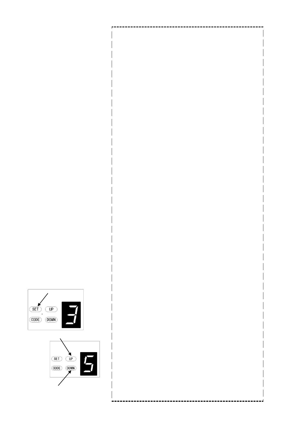
Increase Force
Decrease Force
a) Press and hold the SET button until 3 appears on the display,
then release the button.
The unit is now in force adjustment mode.
b) Press the UP button to increase the force setting or the DOWN
button to decrease the force setting. The maximum force is 5 and
the minimum is 1.
c) Press SET to confirm your setting
NOTE: The factory force setting is 3.
38
5. Automatic Closing
NOTE: We recommend that Photocells (Safety Beam) be used in any
installation setup where the Auto-Close function is enabled.
The Maximum time is 9 minutes. To disable Auto
Close, set time to zero (0).
c) Press SET button to confirm the your selected time.
6. Photocells (safety beam)
NOTE: Make sure the photocell has been correctly installed and uses
Normally Closed contacts to the accessory terminals of the opener
(Figures 15 & 16)
Also note that the photocell function must be disabled if NO
photo beams are fitted, otherwise the door cannot be closed,
and the LED will blink once time as an indication.
a) Press and hold the DOWN button until 11 appears on the
display. To enable the photocell option, press UP again, the
display will indicate an H (enabled) or press DOWN button to
disable photocells (11 will be displayed).
b) Press SET to confirm your choice.
7. Open / Stop / Close Terminals
The O/S/C facility can be used for an external push button switch to
operate the opener. The switch must have voltage free
normally open contacts (Figure 15)
Inease A/C time
Decrease A/C time
Auto Close enabled
Auto Close disabled
Photocell enabled
Photocell disab
led
a) Press and hold the UP button until a horizontal bar is
indicated on the display. Now press UP button once to set
the auto-close time (in minutes).
b) Press the UP button to increase the time, or the DOWN
button to decrease the time.
39
40
Photocell connection (optional) – Figure 15, Figure 16
Switch control connection (optional) – Figure 15
Figure 1
5
Figure 16
Other terminal introduction and application
1. The O/S/C interfaces available. (Figure 18)
Add a new O/S/C button to open or close the door (e.g. interior push-buttons).
2. Flashing light function. (Figures 17 and 18)
There are corresponding interfaces for this function and provide 24v-35v flashing light voltage. Connect the
flashing light with DC 24v-28v, current≤100mA. When using AC 220V power flashing lights, please fit an
adapter and wiring as required.
3. Pass door (SD) protection (Figure18)
This function ensures that the door can’t be opened unless the small pass door is closed. The door panel
won’t be damaged.
42
Attach warning label
Attach the warning about the risk of entrapment in a permanently prominent, clean place. For
example, near the permanently installed buttons used to open and close the garage door
opener.
The opener is equipped with a manual release cord to disengage the shuttle and enable
moving the door by hand while holding the handle down (Figure 19). Pull on the handle to
disengage the shuttle. To re-engage the door simply run opener in automatic mode or move
door by hand until the trolley engages in the belt/chain shuttle.
In situations that a pedestrian door is not installed or available (2nd entrance to garage), it
is recommended that an external disengagement device should be fitted (not supplied)
(Figure 20).
MANUAL DISENGAGEMENT
Figure 19
Figure 20
PLUS 600 PLUS 1000 PLUS 1200
Input voltage
220 - 240V, 50–60 Hz
Max. pull force
600 N
1000 N
1200 N
Max. door area
10.0 15.0 18.0
Max. door weight (Balanced)
80 kg
100 kg
140kg
Max. door height
2400 - 3500mm
2400 - 3500mm
2400 - 3500mm
Drive
Chain / Belt
Chain / Belt
Chain / Belt
Opening / Closing Speed
160mm / Second
160mm / Second
140mm / Second
Drive mechanism
Chain / Belt
Chain / Belt
Chain / Belt
L.E.D
24V / 15pcs LED bulbs
Limit setting
Electronic
Electronic
Electronic
Transformer
Overload protection technology
Radio frequency
433.92 Mhz
433.92 Mhz
433.92 Mhz
Coding Format
Rolling code (7.38 x 10
19
Combinations)
Standard transmitter
2 X
2 X
2 X
Code Storage Capacity
20 different codes
Caution light terminal
Included
Included
Included
Working temperature
Safety Protection
Soft start & Soft stop, photo cell option, caution light option
Protection level
IP20
IP20
IP20
TECHNICAL SPECIFICATIONS
PLUS 600
PLUS 1000
PLUS 1200
43
-40°C - +50°C
-40°C - +50°C
-40°C - +50°C
PLUS 600-Speed PLUS 1000-Speed
220 - 240V, 50–60 Hz
600 N
1000 N
10.0 15.0
80 kg
100 kg
2400 - 3500mm
2400 - 3500mm
Chain / Belt
Chain / Belt
200mm / Second
200mm / Second
Chain / Belt
Chain / Belt
24V / 15pcs LED bulbs
Electronic
Electronic
Overload protection technology
433.92 Mhz
433.92 Mhz
Rolling code (7.38 x 10
19
Combinations)
2 X
2 X
20 different codes
Included
Included
Soft start & Soft stop, photo cell option, caution light option
IP20
IP20
PLUS 600-Speed
PLUS 1000-Speed
44
-40°C - +50°C
-40°C - +50°C
PARTS LISTING
45
Item Qty Description
1 1 L.E.D cover
2 1 Control panel cover-1
3 1 Control panel cover-2
4 1 Main cover
5 1 L.E.D light
6 1 PCB-1
7 1 PCB-2
8 1 DC gear motor
9 1 Motor shaft sleeve
10 1 Transformer
11 1 Transformer plate
12 1 Steel bottom base
Item Qty Description
13 1 Micro switch assy
14 1 Sprocket assy
15 1 Micro switch cover
16 2 U hanging bracket
17 1 Easy-Click bracket
18 1 C rail – steel
19 2 Mounting bracket
20 1 Chain or Belt
21 1 Idler Pulley
22 1 Wheel bracket
23 1 Track ending bracket
24 1 Wall bracket
Item Qty Description
25 1 Panel bracket
26 1 Bent arm
27 1 Straight arm
28 1 Belt connection piece
29 1
Trolley
30 1 Caution card
31 1 Release handle
32 2 Remote Control
33 1 Remote Control Holder
32
33
31
30
28
29
27
25
24
23
22
21
20
19
16
14
13
9
8
1
17
12
15
2
3
4
5
6
7
10
11
18
26
  • Page 1 1
  • Page 2 2
  • Page 3 3
  • Page 4 4
  • Page 5 5
  • Page 6 6
  • Page 7 7
  • Page 8 8
  • Page 9 9
  • Page 10 10
  • Page 11 11
  • Page 12 12
  • Page 13 13
  • Page 14 14
  • Page 15 15
  • Page 16 16
  • Page 17 17
  • Page 18 18
  • Page 19 19
  • Page 20 20
  • Page 21 21
  • Page 22 22
  • Page 23 23
  • Page 24 24
  • Page 25 25
  • Page 26 26
  • Page 27 27
  • Page 28 28
  • Page 29 29
  • Page 30 30
  • Page 31 31
  • Page 32 32
  • Page 33 33
  • Page 34 34
  • Page 35 35
  • Page 36 36
  • Page 37 37
  • Page 38 38
  • Page 39 39
  • Page 40 40
  • Page 41 41
  • Page 42 42
  • Page 43 43
  • Page 44 44
  • Page 45 45
  • Page 46 46

Schartec Move 1000-Speed Installation And Operating Instructions Manual

Category
Garage Door Opener
Type
Installation And Operating Instructions Manual
This manual is also suitable for

Ask a question and I''ll find the answer in the document

Finding information in a document is now easier with AI

in other languages