Page is loading ...

1
Owner’s Manual
Tripp Lite
DC-to-AC Inverters
Models: PINV2000, PINV2000HS, PINV3000
(AG-87A0) (AG-87A1) (AG-87A2)
Español 25 • Français 49
1111 W. 35th Street, Chicago, IL 60609 USA • www.tripplite.com/support
Copyright © 2018 Tripp Lite. All rights reserved.
PROTECT YOUR INVESTMENT!
Register your product for quicker service
and ultimate peace of mind.
You could also win an ISOBAR6ULTRA
surge protector—a $100 value!
www.tripplite.com/warranty
18-11-135-9338A1.indb 1 12/6/2018 3:02:44 PM

2
Congratulations! You’ve purchased a high-quality inverter designed to
function as a mobile energy source powered by your automotive bat-
tery. Tripp Lite inverters convert 12V DC (battery) power into 120V AC
(household) power, allowing you to use equipment you commonly use
at home—computers, appliances, electronics, power tools and more—
while traveling by automobile or working at remote locations that lack
AC power. Tripp Lite inverters include advanced features that protect
your equipment, lengthen the service life of your battery and ensure
you’ll always have battery power to start your vehicle:
• Automatic Overload Protection
• Automatic Low-Battery Protection
• High-Performance DC-to-AC Inversion
• Frequency-Controlled Output Power
• Simple, Maintenance-Free Operation
• GFCI Protected AC Outlets
• USB 5V 2.0A Charging Port(s)
Important Safety Instructions 3
Feature Identification 6
Battery Selection 9
Mounting 10
Battery Connection 14
Operation 18
Troubleshooting/Maintenance 20
Service 23
Warranty & Product Registration 24
Reliable AC Power Wherever You Need It
18-11-135-9338A1.indb 2 12/6/2018 3:02:44 PM

3
Important Safety Instructions
SAVE THESE INSTRUCTIONS!
This manual contains important instructions and warnings
that should be followed during the installation, operation and
storage of all Tripp Lite Inverters.
Location Warnings
• Install your Inverter (whether for a mobile or stationary application)
in a location or compartment that minimizes exposure to heat, dust,
direct sunlight and moisture.
• Although your Inverter is moisture resistant, it is NOT waterproof.
Flooding the unit with water will cause it to short circuit and could
cause personal injury due to electric shock. Never immerse the
unit, and avoid any area where standing water might accumulate.
Mounting should be in the driest location available.
• Leave a minimum of 2 inches (5 cm) clearance at front and back of
the Inverter for proper ventilation. The heavier the load of connected
equipment, the more heat will be generated by the unit. Any
compartment that contains the Inverter must be properly ventilated
with adequate outside airflow to avoid overheating the Inverter.
• Do not install the Inverter directly near magnetic storage media, as
this may result in data corruption.
• Do not install near flammable materials, fuel or chemicals.
• Do not mount unit with its front or rear panel facing down (at any
angle). Mounting in this manner will seriously inhibit the unit’s
internal cooling, eventually causing product damage not covered
under warranty.
18-11-135-9338A1.indb 3 12/6/2018 3:02:44 PM

4
Important Safety Instructions
Battery Connection Warnings
• Multiple battery systems must be comprised of batteries of identical
voltage, age, amp-hour capacity and type.
• Because explosive hydrogen gas can accumulate near batteries
if they are not kept well ventilated, your batteries should not be
installed (whether for a mobile or stationary application) in a “dead
air” compartment. Ideally, any compartment would have some
ventilation to outside air.
• Sparks may result during final battery connection. Always observe
proper polarity as batteries are connected.
• Do not allow objects to contact the two DC input terminals. Do not
short or bridge these terminals together. Serious personal injury or
property damage could result.
• Connect the Inverter to the battery with recommended DC fusing
(see Battery Connection) along with properly sized battery cabling
Ground Connection Warnings
• Safe operation requires connecting the Inverter’s main grounding
screw directly to the frame of the vehicle or earth ground.
Equipment Connection Warnings
Use of this equipment in life support applications where failure of this
equipment can reasonably be expected to cause the failure of the life
support equipment or to significantly affect its safety or effectiveness is
not recommended.
• You may experience uneven performance results if you connect a
surge protector, line conditioner or UPS system to the modified sine
wave output of the inverter.
18-11-135-9338A1.indb 4 12/6/2018 3:02:44 PM

5
Important Safety Instructions
Operation Warnings
• Your inverter produces a modified sine wave, not a pure sine
wave. Inductive loads like a refrigerator or drill are not suitable for
long-term use with a modified sine wave inverter. Otherwise, it may
damage or shorten the working life of the inverter or associated
devices.
• Your inverter does not require routine maintenance. Do not open the
device for any reason. There are no user-serviceable parts inside.
• Potentially lethal voltages exist within the inverter as long as the
battery is connected. During any service work, the battery should
therefore be disconnected.
• Do not connect or disconnect batteries while the inverter is
operating. Dangerous arcing may result.
18-11-135-9338A1.indb 5 12/6/2018 3:02:44 PM
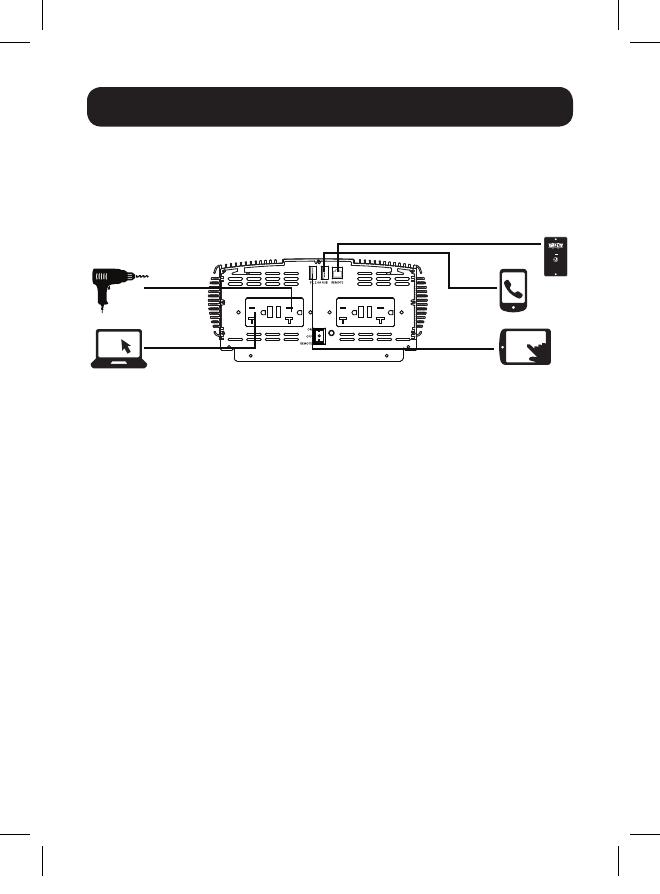
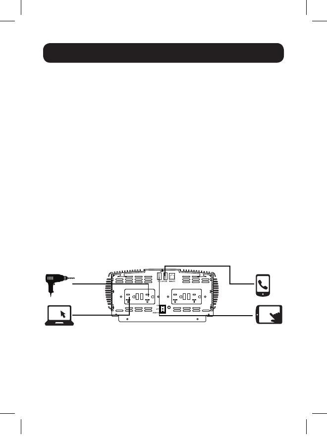
6
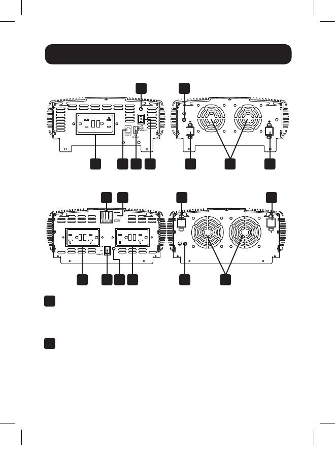
Feature Identification
PINV2000
PINV2000HS/PINV3000
A
GFCI Protected AC Outlets: NEMA 5-15/20R outlets allow you
to connect equipment that normally plugs into an AC utility outlet.
Enhancing safety, the ground fault circuit interrupter switch trips if
there is excessive current on the ground safety wire.
B
USB Charging: 2.0A USB-A charging port(s) support charging of
mobile phones, tablets and other personal electronic devices.
A C
D G
BH E
E
F
F
F
F
A A GC D
B H
18-11-135-9338A1.indb 6 12/6/2018 3:02:46 PM

7
Feature Identification
C
ON/OFF/REMOTE Switch: When you set the switch to the ON
(I) position, the Inverter provides AC power by converting DC
power from the connected 12V battery system. Set the switch to
the OFF (O) position to shut down the Inverter and conserve the
battery’s charge when you are not using connected equipment.
Also set the switch to the OFF position to reset the Inverter if
it has shut down due to overload or other critical events. Both
inverters are equipped with the capability to extend its ON/OFF
control to a remote location with the included PINVRM remote
panel. The remote provides ON/OFF operation and a status LED
to let you know the inverter is ON. See the Operation section for
more information.
D
LED Status Indicators: When the switch is set to the ON
position, the LED system will illuminate green during normal, low
voltage alarm and output short circuit conditions. If there is an
overload, over-temperature, or if a high/low DC voltage shutdown
condition occurs, the LED system will illuminate red.
LED
Operation
Status
Normal
Voltage
(12V)
Low
Voltage
Alarm
Low
Voltage
Shutdown
High
Voltage
Shutdown
Over-
Temperature
Output
Overload
Output
Short
Circuit
Green LED
Status
ON ON OFF OFF OFF OFF ON
Red LED
Status
OFF OFF ON ON ON ON OFF
Alarm OFF ON ON ON OFF OFF OFF
E
Temperature/Load-Controlled Cooling Fan: This fan regulates
the internal temperature of the inverter and prolongs service
life. It will only come on if the temperature or load demand goes
beyond the set thresholds.
F
DC Power Terminals: These positive and negative terminals
connect to the battery via the included or user-supplied cabling.
See Battery Connection for instructions.
18-11-135-9338A1.indb 7 12/6/2018 3:02:46 PM

8
G
Main Ground Screw: Connect to an earth ground or a vehicle
grounding system in order to properly ground the inverter. See
Battery Connection for instructions.
H
Remote Control Module Connector: All models feature a
6-conductor telephone style jack on the front panel for use with
an optional remote control module (Tripp Lite model PINVRM,
included with all models). The remote module allows the Inverter
to be mounted out of sight in a compartment or cabinet, while
operated conveniently from your vehicle’s dashboard. See
Mounting and Operation sections instructions for use of the
remote control module.
Not Shown:
Audible Alarm: The internal audible alarm activates when either a low
or high DC voltage condition exists.
Feature Identification
18-11-135-9338A1.indb 8 12/6/2018 3:02:46 PM

9
Battery Selection
Match Battery Amp-Hour Capacity to Your
Application
Select a battery or system of batteries that will provide your Inverter
with proper DC voltage and an adequate amp-hour capacity to power
your application. Even though Tripp Lite Inverters are highly efficient
at DC-to-AC inversion, their rated output capacities are limited by the
total amp-hour capacity of connected batteries, plus the output of an
alternator (when one is used).
STEP 1) Determine Total Wattage Required
Add the wattage ratings of all equipment you will connect to your
Inverter. Wattage ratings are typically listed in equipment manuals
or on nameplates. If your equipment is rated in amps, multiply that
number times AC utility voltage to estimate watts. (Example: a drill
requires 2.5 amps. 2.5 amps × 120 volts = 300 watts.)
Note: Your Inverter will operate at higher efficiencies around 75% - 80% of
nameplate rating.
Step 2) Determine DC Battery Amps Required
Divide the total wattage required (from Step 1, above) by the battery
voltage to determine the DC amps required, then multiply by 1.2 to
account for conversion losses.
Step 3) Estimate Battery Amp-Hours Required
Multiply the DC amps required (from Step 2, above) by the number of
hours you estimate the equipment will operate exclusively from battery
power before recharging the batteries. This will provide an estimate of
how many battery power amp-hours (from one or several batteries) you
should connect to your Inverter.
Note: Battery amp-hour ratings are usually given for a 20-hour discharge rate.
Actual amp-hour capacities are less when batteries are discharged at faster
rates. For example, batteries discharged in 55 minutes provide only 50% of their
listed amp-hour ratings, while batteries discharged in 9 minutes provide as little
as 30% of their amp-hour ratings.
18-11-135-9338A1.indb 9 12/6/2018 3:02:46 PM

10
Mounting
WARNING!
Mount your Inverter BEFORE DC battery connection. Failure
to follow these instructions may lead to personal injury and/
or damage to the Inverter and connected systems. Ensure the
inverter never is mounted in a vertical position (fan or outlet side
facing up or down). Mounting an inverter in a vertical position
allows debris to enter the unit and inhibit proper operation of its
cooling system, which can void the inverter’s warranty.
Tripp Lite recommends permanently mounting the Inverter in the
configurations illustrated below. The Inverter features integral mounting
brackets on the left and right sides of the unit. The user must supply
mounting hardware and is responsible for determining whether
hardware and mounting surfaces adequately support the weight of the
unit.
Use the measurements as shown in the following diagram to install two
user-supplied fasteners to the right or bottom (wall-mount) mounting
slots of the unit, leaving the heads slightly raised. Slide the unit over
the fasteners to engage the mounting slots. Tighten fasteners. Install
and tighten two additional fasteners to the remaining mounting slots
for proper securement.
Flat Surface
Mount
Wall Mount
18-11-135-9338A1.indb 10 12/6/2018 3:02:47 PM

11
Mounting
PINV2000 Mounting Dimensions*
9.17 in. (233 mm)
5.73 in. (145.5 mm)
0.22 in. (5.6 mm)
0.36 in. (9.1 mm)
9.65 in. (245 mm)
9.17 in. (233 mm)
0.63 in.
(16 mm)
0.63 in.
(16 mm)
*All mounting dimensions are accurate to +/- 0.1 inch (2.5 mm).
18-11-135-9338A1.indb 11 12/6/2018 3:02:47 PM

12
PINV2000HS/PINV3000 Mounting Dimensions*
0.221.65
Mounting
9.90 in. (251.5 mm)
12.87 in. (327 mm)
9.35 in. (237.5 mm)
1.65 in.
(42 mm)
0.22 in.
(5.6 mm)
PINVRM Remote Control Mounting Instructions
1
To mount the remote to a permanent location, ensure the 20 ft.
(6 m) remote cable can reach the inverter’s RJ11 remote port.
*All mounting dimensions are accurate to +/- 0.1 inch (2.5 mm).
18-11-135-9338A1.indb 12 12/6/2018 3:02:47 PM

13
Mounting
3
Using the center-to-center spacing of the mounting holes, mark
the locations for installation.
4
Secure the remote to its permanent location with user-supplied
hardware. Tighten by hand to reduce the possibility of cracking
the remote module at its mounting points.
5
Connect the remote’s wired connector to the inverter’s RJ11 port
labeled “REMOTE”.
6
Set the inverter’s main power switch to the REMOTE (||) position.
7
Test the connection and operation by pressing ON/OFF until the
green status LED shows on the remote module.
STATUS
ON/OFF
PINVRM
2.539 in. (65 mm)
Ø0.157 in. (4 mm)
3.818 in. (97 mm)
4.284 in. (109 mm)
0.104 in. (3 mm)
Ø1.269 in. (32 mm) 0.492 in. (13 mm)
*All mounting dimensions are accurate to +/- 0.1 inch (2.5 mm).
2
The following mounting dimensions* should be used when
installing the remote to a permanent mounting location:
18-11-135-9338A1.indb 13 12/6/2018 3:02:47 PM

14
Battery Connection
WARNING!
Make sure the inverter power switch is in the OFF position,
connect with included DC Wiring to the positive and negative
terminals. Though your Inverter is a high-efficiency converter
of electricity, its rated output capacity is limited by the length
and gauge of the cabling running from the battery to the unit.
Use the included cabling or the shortest length and largest
diameter cabling (see the Recommended Cabling and Fusing
Chart below) with ring terminals to fit your Inverter’s DC Input
terminals. Shorter and heavier gauge cabling reduces DC voltage
drop and allows for maximum transfer of current. Your Inverter
is capable of delivering peak wattage at up to 200% of its rated
continuous wattage output for brief periods of time. Heavier
gauge cabling should be used when continuously operating heavy
draw equipment under these conditions. To protect the battery
system, it is also recommended to install a user-supplied UL-
rated ANL fuse and fuse block 7 inches from the battery bank’s
positive terminal connection. The inverter has its own internal DC
fusing to protect against short circuits at the inverter’s output.
Recommended Cabling and Fusing
Model
Included Wire
Gauge and Quantity
(2x Red / 2x Black)
Included
Cabling
Length
Recommended
DC Fuse Size
(User-Supplied)
Ground
Wire Size
and Length
(Included)
PINV2000 4x 6 AWG 3 ft.
(1m)
300A ANL Fuse 16 AWG
(3 ft.)
PINV2000HS 4x 5 AWG 3 ft.
(1m)
440A ANL Fuse 16 AWG
(3 ft.)
PINV3000 4x 5 AWG 3 ft.
(1m)
440A ANL Fuse 16 AWG
(3 ft.)
18-11-135-9338A1.indb 14 12/6/2018 3:02:47 PM
15
Battery Connection
To Connect the Inverter to Batteries:
1. Locate the positive (+) red and negative (-) black terminals on the
left side of the inverter.
2. From the positive and the negative terminals, remove the hex nut,
split lock, and flat washer.
3. Place the positive ring connector onto the positive inverter
terminal. Place the negative ring connector onto the negative DC
input terminal.
4. Place a flat washer and split lock on top of each ring connector.
Put the positive and negative hex nuts over these and tighten to
create a secure connection and prevent excessive heating at this
connection. Insufficient tightening of the terminals could void your
warranty. See Specifications for recommended cable sizing.
5. Connect the red positive (+) wire to the positive (+) connector on
your battery system and connect the black negative (-) wire to the
negative (-) connector on your battery system. It is recommended
that the positive connection should have a UL-rated ANL fuse and
fuse block (see Recommend Cabling and Fusing table) installed
a minimum of 7 inches or maximum of 18 inches from the battery
system’s positive connector for battery system protection.
6. Connect Ground: Using the ground wire, directly connect the
Main Ground Screw to the vehicle’s chassis or earth ground.
See Feature Identification to locate the Main Ground Screw.
All installations must comply with national and local codes and
ordinances.
FUSE
18-11-135-9338A1.indb 15 12/6/2018 3:02:48 PM
16
Battery Connection
WARNING!
• Failure to properly ground your Inverter to a vehicle’s chassis
or earth ground may result in a lethal electrical shock hazard.
• Never attempt to operate your Inverter by connecting it
directly to output from an alternator rather than a battery or
battery bank.
• Observe proper polarity with all DC connections.
Vehicular Applications
Your Inverter’s nominal DC input voltage must match the voltage
of your battery or batteries. 12V DC is used in most vehicular
applications. It is possible to connect your Inverter to the main battery
within your vehicle’s electrical system. In many vehicular contexts, the
Inverter will be connected to one or more dedicated auxiliary (house)
batteries, which are isolated from the drive system to prevent possible
draining of the main battery.
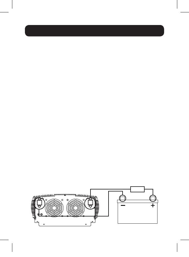
PINV2000 12V Battery Connection
12V
FUSE
18-11-135-9338A1.indb 16 12/6/2018 3:02:48 PM
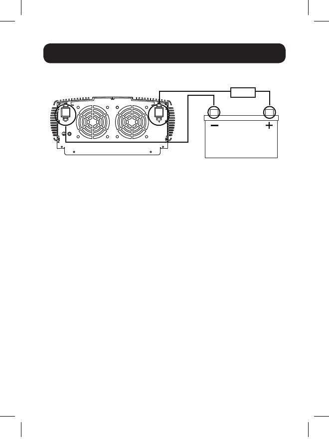
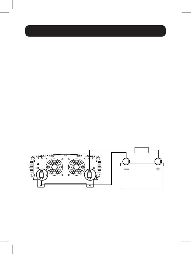
17
Battery Connection
PINV2000HS/PINV3000 12V Battery Connection
12V
FUSE
18-11-135-9338A1.indb 17 12/6/2018 3:02:49 PM
18
Operation
Operating Modes
After mounting and connecting your Inverter according to the
instructions in this manual, use the ON/OFF/REMOTE switch to choose
the Inverter’s operating mode.
ON: When you set the switch to the ON (I) position, the Inverter
provides AC power to connected equipment by converting DC power
from your vehicle’s battery. The green LED will illuminate to indicate it
is working.
OFF: Set the switch to the OFF (O) position to shut down the Inverter
completely. Doing this will prevent it from drawing power from your
vehicle’s battery. Also set the switch to the OFF position to reset the
Inverter if it has shut down due to low battery, overload or other critical
condition.
REMOTE: When you set the switch to the REMOTE (II) position, the
Inverter provides AC power to connected equipment by converting
DC power from your vehicle’s battery. The green LED will illuminate to
indicate it is working. You can then power the inverter ON/OFF from a
remote location via the included PINVRM remote. This remote switch
can be mounted in the vehicle or a permanent mount application (see
Mounting section for more information). The green LED on the remote
will illuminate to indicate the inverter is in the ON operating mode.
1. Connect the Inverter (see Battery Connection section).
STATUS
ON/OFF
PINVRM
18-11-135-9338A1.indb 18 12/6/2018 3:02:49 PM
19
Operation
2. Switch the Inverter’s ON/OFF switch to the ON (I) position. If you
are using the included PINVRM remote panel, set the switch to
the REMOTE (II) position and press the ON button on the remote
panel.
3. The green LED indicator will illuminate on the unit or remote panel
(If installed), indicating the Inverter is receiving power.
4. Switch the Inverter’s ON/OFF/REMOTE switch to the OFF (O)
position. The green LED may flash briefly and/or the internal
speaker may beep briefly. This is normal.
5. Make sure the device(s) to be operated is turned OFF.
6. Plug the device(s) into the Inverter’s AC outlet(s).
7. Switch the inverter’s ON/OFF/REMOTE switch to the ON (I) or
REMOTE (II) positions. If using the remote position, connect the
PINVRM cable connector to the RJ11 jack on the unit labeled
REMOTE and press the ON/OFF momentary switch to power the
inverter.
8. Turn the device(s) on.
9. To disconnect, reverse the above procedure.
USB Charging Operation
The USB charging port is ON when the Inverter is connected to a 12V
DC power source. Connect your device(s) to this port for USB charging
up to 2.0A. Remove your device(s) from the USB port when it has
finished charging to reduce battery drain or start vehicle.
18-11-135-9338A1.indb 19 12/6/2018 3:02:49 PM

20
Troubleshooting/Maintenance
Troubleshooting Protection Modes
The Inverter may shut down and cease supplying AC power under
certain conditions in order to protect the unit, the battery and
connected equipment.
The LED automatically illuminates green when the Inverter is plugged
into a 12V DC power source and turned on. If conditions cause the
Inverter’s LED to illuminate red, its alarm to sound or the inverter
automatically turns itself off, follow these instructions to restore the
unit to normal operation:
Condition Explanation Solution
Low-Voltage
Alarm and
Low-Voltage
Cutoff
When the power input
from the vehicle’s battery
drops to approximately
10.5V DC, the low-
voltage alarm will sound.
When the voltage goes
down below 10V DC, the
inverter shuts off.
Start the vehicle to
recharge the battery. See
Resetting the Inverter
for more information.
Overvoltage
Alarm and
Shutdown
When the power input
from the vehicle’s
battery exceeds 16V DC,
high voltage overload
protection occurs and
shuts down the inverter.
Overload
The continuous load
demand from the
equipment or device
being operated exceeds
the continuous load
rating of the inverter.
Use a higher capacity
inverter or lower rated
device.
18-11-135-9338A1.indb 20 12/6/2018 3:02:49 PM
/