Page is loading ...

TM
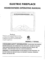
Media Mantel with
33-IN Infrared
Electric Fireplace
ASSEMBLY, CARE & USE INSTRUCTIONS
MODEL # 1317FM-33-202
ITEM # 1031288
Questions, problems, missing parts?
Before returning to your retailer,
call our customer service department at
1-855-571-1044 9 a.m. - 5 p.m., EST, Monday - Friday
www.greentouchhome.com
Date Purchased _______________________
Français p. 19
Español p. 38

J
J
B
C
F
D
E
G
L
I
L
H
K
P
Q
O
N
M
M
I
J
J
A
2
PACKAGE CONTENTS
PART DESCRIPTION QUANTITY
A Top 1
B Center Panel 1
C Left Middle Wall 1
D Right Middle Wall 1
E Left Outer Wall 1
F Right Outer Wall 1
G Left Door (with hinges) 1
H Right Door (with hinges) 1
I Shelf 2
J Back Panel 2
PART DESCRIPTION QUANTITY
K Base 1
L Wood Door Panel 2
M Insert Brace 2
N Front Trim 1
O Insert 1
P Remote Control 1
Q Battery 2

AA BB CC
DD
EE FF
3
HARDWARE CONTENTS (NOT SHOWN ACTUAL SIZE)
PART DESCRIPTION QUANTITY
AA Wood Dowel 24
BB Long Bolt 22
CC Washer 22
DD Back Panel Screw 20
EE Shelf Pin 8
FF Touch-up Pen 1

4
When using electrical appliances, basic precautions
should always be followed to reduce the risk of re,
electric shock and injury to persons, including the
following:
DANGER
• Read all instructions before using this heater.
• If the information in this manual is not
followed exactly, an electric shock or re may
result causing property damage, personal
injury or loss of life.
• This product is intended to t most Plasma
and LCD televisions (up to 80 inches and
weighing a maximum of 125 pounds). Using
this item with loads heavier than the stated
maximum can result in tipping and/or
instability, which can result in injury or even
death.
WARNING
• This appliance is hot when in use. To avoid
burns, DO NOT let bare skin touch hot
surfaces. Keep combustible material, such as
furniture, pillows, bedding, papers, clothes and
curtains at least 3 feet from this appliance and
keep them away from the sides and rear.
• Extreme caution is necessary when any heater
is used by or near children or individuals with
disabilities and whenever the replace is left
operating and unattended.
• DO NOT run cord under carpeting. DO NOT
cover cord with throw rugs, runners, or similar
coverings. DO NOT route cord under funiture or
appliances. Arrange cord away from trafc areas
and where it will not be tripped over.
• DO NOT insert or allow foreign objects to enter
any ventilation or exhaust opening as this may
cause an electric shock or re, or damage the
appliance.
• This appliance has hot and arcing or sparking
parts inside. DO NOT use it in areas where
gasoline, paint or ammable vapors or liquids
are used or stored. This replace should not be
used as a drying rack for clothing. Christmas
stockings or decorations should not be hung in
the area of it.
• Use this appliance only as described in the
manual. Any other use is NOT recommended
by the manufacturer and may cause re,
electric shock or injury to persons.
CAUTION
• If possible, ALWAYS unplug this appliance
when not in use.
• DO NOT operate any heater with a damaged
cord or plug or after the heater malfunctions.
DO NOT operate any heater if it has been
dropped or damaged in any manner.
Disconnect power at service panel and have
heater inspected by a reputable electrician
before reusing.
• Any repairs to this replace should be carried
out by a qualied service person.
• Under no circumstances should this replace
be modied. Parts having to be removed for
servicing must be replaced prior to operating
this replace again.
• DO NOT use outdoors.
• This heater is not intended for use in
bathrooms, laundry areas and similar indoor
locations.
NEVER place heater where it may fall into a
bathtub or other water container.
• To disconnect this appliance, turn controls to
the off position, then remove plug from outlet.
• ONLY connect to properly grounded outlets.
• This appliance, when installed, must be
electrically grounded in accordance with local
codes, with the current CSA C22.1 Canadian
Electrical Code or follow U.S.A. Installations,
follow local codes and the National Electrical
Code, ANSI/NFPA N0.70.
SAFETY INFORMATION
IMPORTANT INSTRUCTIONS

A B C
D
Grounding Pin
Grounding Pin
Grounding Means
Metal
Screw
Cover of
Grounding
Box
Adapter
SAVE THESE INSTRUCTIONS
5
• To prevent a possible re, DO NOT block
air intakes or exhaust in any manner. DO
NOT use on soft surfaces, like a bed, where
opening may become blocked.
• The heaters MUST NOT be located
immediately below a socket-outlet.
• ALWAYS plug heaters directly into a wall
outlet/receptacle. NEVER use with an
extension cord or re-loadable power tap (outlet
/ power strip).
• DO NOT slide insert on top of wood to avoid
scratching wood surface.
• DO NOT place any object on top of the insert
or block the air intakes / vents as this can
cause the unit to overheat and could cause
a re.
Electrical Connection
• A 15-Amp, 120-volt, 60 Hz circuit with
a properly grounded outlet is required.
Preferably, the replace will be on a dedicated
circuit as other appliances on the same circuit
may cause the circuit breaker to trip or the
fuse to blow when the heater is in operation.
The unit comes standard with 6-ft. three-wire
cord, exiting from the rear of the replace.
DO NOT exceed the current rating of the
current tap.
Grounding Instruction
• This heater is for use on 120 volt.The cord
has a plug as shown below. See illustration
for grounding instruction. An adapter as
shown at C is available for connecting
three-blade grounding type plugs to two slot
receptacles. The green grounding
lug extending from the adapter must be
connected to a permanent ground such as
a properly grounded outlet box. The adapter
should not be used if a three-slot grounded
receptacle is available.
SAFETY INFORMATION (CONT’D)

AA
BB
CC
BB
CC
BB
1
2
BB
CC
BB
AA
AA
K
CC
BB
C
K
D
Hardware Used
Hardware Used
6
Before beginning assembly of product, make sure
all parts are present. Compare parts with
package contents list and hardware contents list.
If any part is missing or damaged, do not attempt
to assemble the product.
Estimated Assembly Time: 45 minutes
Tools Required for Assembly (not included):
Phillips screwdriver
1. Insert two Wood Dowels (AA) into each side of
Base (K).
2. Place Left Middle Wall (C) and Right Middle Wall (D)
onto Base (K), securing with four Washers (CC)
and four Long Bolts (BB).
PREPARATION
ASSEMBLY INSTRUCTIONS
x 4
x 4
x 4
Wood Dowel
Long Bolt
Washer

AA
AA
3
AA
B
Hardware Used
4
B
C
D
BB
CC
BB
CC
BB
CC
5
N
Hardware Used
BB
CC
BB
CC
BB
CC
K
7
3. Insert two Wood dowels (AA) into each side
of Center Panel (B).
4. Align the dowels in Center Panel (B) to Left
Middle Wall (C) and Right Middle Wall(D).
Insert dowels into predrilled holes and press tight.
ASSEMBLY INSTRUCTIONS (CONT’D)
AA
x 4Wood Dowel
5. Place Front Trim (N) onto Base (K), secure with
two Washers (CC) and two Long Bolts (BB).
Long Bolt x 2
x 2Washer

BB
CC
AA
AA
AA
6
7
BB
BB
CC
CC
AA
AA
K
A
E
F
C
D
F
E
Hardware Used
Hardware Used
BB
CC
AA
AA
AA
8
6. Insert two Wood Dowels (AA) into outer holes on right
side of Base (K). Attach Right Outer Wall (F), securing
with two Washers (CC) and two Long Bolts (BB).
Repeat for left Outer Wall (E).
7. Insert two Wood Dowels (AA) into the top
outer holes on Left Outer Wall (E), Left Middle
Wall (C), Right Middle Wall (D) and Right Outer
Wall (F). Attach Top (A), securing from underneath
with ten Washers (CC) and Long Bolts (BB).
ASSEMBLY INSTRUCTIONS (CONT’D)
BB
BB
CC
CC
Long Bolt
Long Bolt
x 4
x 10
x 4
x 10
Washer
Washer
AA
AA
x 4
x 8
Wood Dowel
Wood Dowel

DD
EE
2
J
J
DD
1
EE
BB
CC
AA
BB
CC
AA
9
10
8
DD
M
M
J
I
Hardware Used
Hardware Used
BB
CC
AA
BB
CC
AA
2
J
J
DD
1
EE
BB
AA
CC
EE
9
9. From behind the assembly, attach Back Panel (J)
to shelving areas using Back Panel Screws (DD).
Repeat for remaining Back Panel (J).
10.Insert Shelf Pins (EE) at desired height, ensuring they
are level. Place Shelf (I) on top of Shelf Pins (EE).
Repeat for remaining the Shelf (I).
8. From behind the assembly, insert four Wood
Dowels (AA) into Base (K), attach Insert Braces (M),
secure with two Washers (CC) and Long Bolts (BB).
ASSEMBLY INSTRUCTIONS (CONT’D)
x 20
x 8
Back Panel Screws
Shelf Pin
Hardware Used
BB
CC
Long Bolt x 2
x 2Washer
AA
x 4Wood Dowel

11
H
10
ASSEMBLY INSTRUCTIONS (CONT’D)
11. Hold the door and align the hinge body with the
hinge plate mounted to the replace wall. Align
and slide the hooks/catches on the hinge body
into the recesses on the mounting plate while
lightly pushing the door towards back of
replace mantel. Then press on the back part
of the hinge body until you hear it click into
place. Repeat for other hinges.
To remove press the square button at the back
of the hinge body to release the hinge from the
mounting bracket. Unlock both hinges and pull
the door away from the replace body
NOTE: Use the pre-assembled levelers on the
base of the replace to level the unit. Twist the
levelers counter clockwise to increase the
height, twist the clockwise to decrease the
height.
12. If you need to adjust the doors, do so in the following manner.
To adjust door up or down, loosen screws (a) on both hinges, adjust door, and retighten screws.
To adjust door left or right, turn screws (b) on both hinges, in or out.
To adjust door in or out, loosen screws (c) on both hinges, adjust door, and retighten screws.

13
14
O
11
ASSEMBLY INSTRUCTIONS (CONT’D)
13. From behind the assembly, remove the
preassembled insert brackets from the middle
area. Save brackets and screws for future use.
14. With the help of another person, position the
Insert (O) into opening of mantel assembly.
Note: DO NOT plug the Insert (O) into power outlet yet.
CAUTION: DO NOT slide the insert on top of wood
to avoid scratching wood surface.

L
L
L
1
2
3
1
1
2
2
3
3
4
4
L
15
O
12
16. The pre-installed glass door panels can be switched out with the included wood door panels (L).
1. Remove the silicone trim along the outer edges of the glass panel on the inside of the door. Start
at a corner and pull to remove the four pieces. Be careful not to damage the silicone trim as it will
be used to secure the new panel.
2. Remove the glass panel from the door frame, then insert the included wood door panel (L).
3. Using your nger press the silicone trim back into place. Move around the outer edge of the panels
until all four sides are secure.
CHANGE DOOR PANELS (OPTIONAL)
ASSEMBLY INSTRUCTIONS (CONT’D)
15. Re-attach insert brackets with previously removed
screws to secure Insert (O).
Assembly is now complete. With the help of another
person, move the assembly to the nal desired
location. Once it is in position, plug the Insert (O)
into the power outlet.

M
M
M
M
M
M
AAA 1.5V
AAA 1.5V
M
M
AAA 1.5V
AAA 1.5V
13
Control Panel Remote Control
Note: The control panel is a touch screen. It will appear black. Touch the control panel once to
“wake up” the controls. This will cause the controls to light up. Which ever icon you touch will display
it’s last setting when you do this. At this time you can press the corresponding icon to the function you
would like to adjust. After 5 seconds the touch screen will fade to black.
Power Function
• Press the POWER ICON to turn the main power to the unit ON or OFF.
• When the unit is powered ON, the lights under the emberbed will glow to indicate the unit
has power.
• If any functions are stored in memory then they will resume at the last setting .
Flame Brightness Function
• Press the FLAME BRIGHTNESS ICON to adjust the ame brightness.
• If the unit main power is OFF, you can press the FLAME BRIGHTNESS ICON to power ON
the unit and ame brightness will resume at the last setting.
• Press the FLAME BRIGHTNESS ICON again to scroll up through the ame brightness
settings: 1, 2, 3, 4, 5, OF.
Temperature Function
• If the unit is powered OFF, you can press the TEMPERATURE ICON to power ON the unit.
The emberbed will glow at the lowest brightness setting unless a different setting was saved
in the memory.
• Press and hold the TIMER ICON for 5 seconds to toggle between 5°F (3°C) increments and
1ºF (1°C) increments when setting the temperature. The unit will beep to indicate that the change
has taken place. The factory default temperature is 5°F (3°C) increments.
Note: This option is only available if using the control panel.
• Hold down the TEMPERATURE ICON for 5 seconds to toggle between Fahrenheit and Celsius.
An “F” or “C” will display next to the temperature.
Note: This option is only available if using the control panel.
• Press and hold the TEMPERATURE ICON for 10 seconds to disengage the heater function.
Press and hold the TEMPERATURE ICON for 10 seconds again to engage the heater
function. (See HEATER OVERRIDE section below for more details).
Increase/Decrease Button
• Press the INCREASE/DECREASE button to adjust the heater’s thermostat setting.
• Press the INCREASE/DECREASE button again to scroll up through the pre-set temperature settings:
The thermostat setting range is 65°F (18°C) to 90ºF (32°C), HI (High) and OF.
• Set the temperature to “HI” to have the heater run continually.
To use the remote control,
rst insert two AAA batteries
(included) into the remote
control. Ensure the polarities
of the battery match the inside
of the battery compartment.
OPERATING INSTRUCTIONS

12
14
Timer Function
• Press the TIMER ICON to set the countdown for the unit’s main power.
• If the unit is powered OFF, you can press the TIMER ICON to power ON the unit. The
emberbed will glow at the lowest brightness setting unless a different setting was saved in
the memory.
• Press the TIMER ICON again to scroll through the timer settings, which are: 30, 1h, 2h, 3h,
4h, 5h, 6h, 7h, 8h, 9h, OF. (30 means 30 minutes, OF means OFF)
• When the timer reaches zero, it will turn OFF the main power and will maintain all the settings
in memory.
HEATER OVERRIDE
The power to the heater can be disengaged to prevent the heater from being accidentally or
unintentionally powering on. This feature is primarily added to help prevent children from powering
on the heater when it is not desired.
• To engage the heater override function press and hold the HEATER ICON for 10 seconds. The
symbol E3 will display. The heater function is now locked. If the HEATER ICON is pressed again E3
will appear then fade.The Flame, Downlight and Timer functions will operate normally. Only the heater
and blower are disengaged.
• To unlock the heater function, press and hold the HEATER ICON for 10 seconds. The symbol
E3 will display. The heater function is now engaged. By pressing the HEATER ICON again you will be
able to adjust the heat temperature to your desired temperature.
MEMORY FUNCTION
This unit has a memory function that allows you to turn off the MAIN POWER and retains all the other
function settings (excluding the TIMER function).
• When the unit’s main power is OFF, press the POWER ICON once on the insert control panel or
on the remote control to power the unit ON and “wake up” the individual function at the last setting.
Press the icon again to adjust it and press the main POWER ICON on the insert or on the remote
control to turn the unit OFF and save the new setting into memory.
• When the unit is powered ON, the LED readout will show the saved temperature setting. If a
temperature setting was not saved, it will show the ame brightness setting saved in memory. If
neither one has a setting saved to memory, then only the emberbed will glow (as a power light indicator).
• To reset the memory, hold down the main POWER ICON for 10 seconds at any time. When this
happens, the LED readout will blink with two zeros three times and the unit will be shut down.
• Another way to reset the memory is to unplug the unit from the wall.
OPERATING INSTRUCTIONS (CONT’D)

P
AAA 1.5V
AAA 1.5V
15
Replacing the Remote Control Batteries
When the remote control (P) stops operating or its
range seems reduced, it is time to replace the
batteries. Note:The batteries should be removed if the
product is to be left unused for a long time.
1. The battery compartment is located on the back
of the remote control (P).
2. Remove battery cover from the back of remote
control (P) and remove the old batteries.
3. Insert 2pcs AAA batteries, ensuring the polarities of
the battery match the inside of the battery
compartment.
4. Re-insert the battery door.
Disposal of Used Batteries
A battery may contain hazardous substances that could be
endangering the environment and human health.
• This symbol marked on the battery and/or packaging indicates that
used battery shall not be treated as municipal waste. Instead it shall
be left at the appropriate collection point for recycling.
• By ensuring the used battery is disposed of correctly, you will help
prevent potential negative consequences for the environment and
human health. The recycling of materials will help to conserve
natural resources.
• Do not dispose of batteries in re. batteries may explode or leak.
For more information about collection and recycling of used batteries,
please contact your local municipality, your waste disposal service or
the point-of-sale where you purchased this battery.
Note: Do not mix old and new batteries.
Do not mix alkaline, standard (carbon zinc), or rechargeable (nicad, nimh, etc) batteries.
Non-rechargeable batteries are not to be recharged. Exhausted batteries are to be removed from
the product.
Harmful if swallowed.
• Make sure the unit is turned OFF, unplugged and the heating elements of heater are cool
whenever you are cleaning the heater or replace.
• Clean the metal trim using a water-dampened soft, clean cloth. DO NOT use brass polish or
household cleaners as these products will damage the metal trim.
• The motors used on the fan and the ame generator assembly are pre-lubricated for extended
bearing life and require no further lubrication. However, periodic cleaning/vacuuming of the fan/
heater and air intake/output vents is recommended.
• When the heater is not in use, the power cord should be stored properly to avoid contact with hot
or sharp objects.
• Any other servicing should be performed by an authorized service representative.
• Tips for using touch-up pen (FF): For scratches, stroke in direction of scratch. For worn areas, stroke
in the direction of wood grain. Rub excess colorant promptly with a soft cloth.
CARE AND MAINTENANCE

16
TROUBLESHOOTING
PROBLEM POSSIBLE CAUSE SOLUTION
Error E1 displayed on
control panel.
The overheat sensor
has been engaged.
Unplug unit, wait 15-20 minutes, then the sensor will
reset itself. Plug the unit back in and turn on the heater.
If the problem persists, call customer service.
Note: The other functions will work normally excluding
the heater. Until the problem is solved, the error will only
appear/sound when the heater button is pressed.
Error E2 displayed on
control panel.
The thermostat
sensor is broken or
not working correctly.
Unplug unit, wait 15-20 minutes, then the sensor will
reset itself. Plug the unit back in and turn on the heater.
If the problem persists, call customer service.
Note: The other functions will work normally excluding
the heater. Until the problem is solved, the error will only
appear/sound when the heater button is pressed.
Error E3 displayed on
control panel.
Heater override
function is engaged
To unlock the heater, simply press and hold the
temperature button for 10 seconds (See page 14
Heater Override Section for more details).
No power; logs do not
glow.
The unit does not
have power.
Check that the power cord is securely plugged into a
standard 120V outlet. Then check to make sure the unit
is powered on.
No ame effect but logs
are glowing.
The ame effect is
powered off.
Push the ame brightness button until desired level is
achieved.
Heater and blower
do not power on but rest
of functions are working.
Heater override
function is engaged
To unlock the heater, simply press and hold the
temperature button for 10 seconds (See page 14
Heater Override Section for more details).
Power cord gets warm to
the touch.
Normal operation. This is normal for a heater appliance as it requires
more current to operate. Check the connections of
the appliance cord and the outlet. Make sure the plug
ts tightly into the outlet. During use, check the plug
and outlet frequently to determine if it is HOT; if so,
discontinue use of the appliance and consult with a
qualied electrician to check or change the overheating
outlet(s).
Remote control does not
work.
Weak or failing
batteries.
Replace with 2 AAA batteries. (See page 15 for more
information.)
Remote control
signal is weak and only
works sometimes
Pressing the buttons
too quickly.
Press the buttons slowly and steadily to ensure the
transmitter recognizes the request.
Using the remote
control too far away or
at an off angle.
Move closer to the insert; the remote control will only
work within a distance of 20 feet and 45 degrees to ei-
ther side from the front of the replace insert.
Fan motor continues to
blow after unit is powered
off
Normal operation. This is a standard feature; the blower runs for an
additional time to cool off heater tubes.

17
The manufacturer warrants that your new Electric replace is free from manufacturing and material
defects for a period of one year from date of purchase, subject to the following conditions and
limitations.
Install and operate this Electric replace in accordance with the installation and operating instructions
furnished with the product at all times. Any unauthorized repair, alteration, willful abuse, accident, or
misuse of the product shall nullify this warranty.
This warranty is non-transferable, and is made to the original owner, provided that the purchase was
made through an authorized supplier of the product.
The warranty is limited to the repair or replacement of part(s) found to be defective in material or
workmanship, provided that such part(s) have been subjected to normal conditions of use and
service, after said defect is conrmed by the manufacturer’s inspection.
The manufacturer may, at its discretion, fully discharge all obligations with respect to this warranty by
refunding the wholesale price of the defective part(s).
Any installation, labor, construction, transportation, or other related costs/expenses arising from
defective part(s), repair, replacement, or otherwise of same, will not be covered by this warranty, nor
shall the manufacturer assume responsibility for same.
The owner/user assumes all other risks, if any, including the risk of any direct, indirect or
consequential loss or damage arising out of the use, or inability to use the product, except as
provided by law.
All other warranties-expressed or implied-with respect to the product, its components and
accessories, or any obligations/liabilities on the part of the manufacturer are hereby expressly
excluded.
The manufacturer neither assumes, nor authorizes any third party to assume on its behalf, any other
liabilities with respect to the sale of the product.
The warranties as outlined within this document do not apply to non accessories used in conjunction
with the installation of this product.
This warranty is void if:
1. The replace is subjected to prolonged periods of dampness or condensation.
2. Any unauthorized alteration, willful abuse, accident, or misuse of the product.
3. You do not have the original receipt of purchase.
ONE-YEAR LIMITED WARRANTY

18
M
H
L
W
I
GG HH II JJ KK LL
REPLACEMENT PARTS
PART DESCRIPTION PART #
GG Hardware Pack PU17-1317FM-001
HH Knob PU17-1317FM-002
II Insert Bracket Insert-Side-MB
JJ Drawer Glide PU17-1317FM-004
KK Hinge PU17-1317FM-005
LL Floor Leveler PU17-1317FM-006
PART DESCRIPTION PART #
G Left Door
PU17-1317FM-007
H Right Door
PU17-1317FM-008
I Shelf
PU17-1317FM-009
L Wood Door Panel PU17-1317FM-010
M Insert Brace PU16-232628-MB
O Insert 3322-CG-BB
P Remote Control
PU18-33CB-RC
W Glass Door Panel PU17-1317FM-010
For replacement parts, call our customer service department at 1-855-571-1044, 9 a.m. - 5 p.m., EST,
Monday - Friday.
PO
G
/