Page is loading ...

Folding Upright Bike with Pulse
IMPORTANT: Read all instructions carefully before using this product.
Retain this owner’s manual for future reference. The specifications of
this product may vary from this photo, subject to change without notice.
OWNER’S MANUAL
4225.2-083018


1
TABLE OF CONTENTS
SERVICE ------------------------------------------------------------------------ 2
LABEL PLACEMENT --------------------------------------------------------- 3
IMPORTANT SAFETY GUIDELINES ------------------------------------ 4
OVERVIEW DRAWING ------------------------------------------------------ 6
PARTS LIST -------------------------------------------------------------------- 7
HARDWARE & TOOL LIST ------------------------------------------------ 9
ASSEMBLY --------------------------------------------------------------------- 10
CONSOLE FUNCTIONS ---------------------------------------------------- 17
STORAGE ----------------------------------------------------------------------- 19
OPERATIONS & ADJUSTMENTS ---------------------------------------- 20
TRANSPORT ------------------------------------------------------------------ 24
MAINTENANCE & TROUBLESHOOTING ----------------------------- 25
TROUBLESHOOTING ------------------------------------------------------ 26
WARRANTY -------------------------------------------------------------------- 27
PARTS REQUEST FORM -------------------------------------------------- 28

2
SERVICE
IMPORTANT: FOR NORTH AMERICA ONLY
For damaged or defective product, questions, replacement parts or any other service
support, please contact our customer service department by the below methods:
For The Best Service, please Email:
service@paradigmhw.com
Response Time: 1-2 Business Days
Emailing us with the information above will be the best method to receive a response during
peak business hours
Website:
www.paradigmhw.com
Toll-Free:
1-844-641-7921
(8:00 AM - 5:00 PM Pacific Standard Time, Monday thru Friday)
Response time may vary via calling
Please have the following information ready when requesting for service:
Your name
Phone number
Model number
Serial number
Part number
Proof of Purchase
For damaged or defective product please contact our customer service before returning to
the store.
Paradigm Health & Wellness, Inc.
1189 Jellick Ave.
City of Industry, CA 91748, USA

3
LABEL PLACEMENT

4
IMPORTANT SAFETY GUIDELINES
Basic precautions should always be followed, including the following safety guidelines
when using this equipment. Read all of the guidelines before using this equipment.
1. Make sure your equipment is correctly assembled before you use it.
2. Be sure all screws, nuts, and bolts are tightened prior to use.
3. Before exercising and to avoid injuring your muscles, it is highly recommended that you perform
warm-up exercises for each muscle group.
4. Make sure all the components are not damaged and are in working order before using.
5. This equipment should be placed on a stable, flat surface. Using a mat or similar covering
material on the ground is recommended.
6. Wear proper fitness apparel when using this equipment. Do not wear loose clothing or
accessories that may get caught by any part of the equipment.
7. Make sure all the components are not damaged and are in working order before using.
8. Remember to tighten the pedaling straps. Keep dry. Do not operate the equipment in wet or
moist condition.
9. Only one person should use the equipment at a time.
10. Keep children under the age of 13 and pets away from the equipment while in use. This
equipment is designed for adults only.
11. Never operate this equipment if it is damaged, if it is not working properly, has been dropped, or
damaged. If a problem is encountered, contact Customer Service before using the equipment
again.
12. Do not use the equipment outdoors. This equipment is for household use only.
13. Only perform maintenance or adjustments that are instructed in this manual. Never drop or
insert any object into any opening. Should any problems arise, discontinue usage of the
equipment and contact Customer Service.
14. Be careful to always hold onto the handlebars when you’re mounting and dismounting. Be
careful to have the pedals at their lowest point when stepping off.
15. Hold onto the handlebars and use both the pedals in tandem to ensure a smooth, effective
workout.
16. This product requires a minimum of 6 square feet around for safe operation.
17. If you feel any chest pains, nausea, dizziness, or shortness of breath while operating the
equipment, you should stop exercising immediately, and consult your physician before
continuing.
18. This equipment is not intended for use by persons with reduced physical, sensory or mental
capabilities, or lack of experience and knowledge, unless they have been given supervision or
instruction concerning use of the equipment by a person responsible for their safety.
19. DO NOT pedal in reverse.
20. The maximum weight capacity for this product is 250lbs/ 113kgs and should be
assembled by two or more people.
21.WARNING: CANCER AND REPRODUCTIVE HARM--WWW.P65WARNINGS.CA.GOV.

5
IMPORTANT SAFETY GUIDELINES
WARNING: Before beginning any exercise program consult your physician. This is
especially important for the people who are over 35 years old or who have pre-existing health
problems. Do not use this equipment without your physician’s approval.
WARNING: Do not allow children to use this machine.
WARNING: Keep children under the age of 13 away from the machine while in use.
WARNING: Keep body parts, hair, loos clothing, and jewelry clear of all moving parts.
WARNING: Do not attempt to service the unit yourself. Discontinue use and contact
Customer Service.
CAUTION: Read all instructions carefully before operating this product. Retain this
Owner’s Manual for future reference.
!
!
!
!
!
!

6
OVERVIEW DRAWING

7
PARTS LIST
No.
Description
Q’ty
No.
Description
Q’ty
01
Main Frame
1
28
Short Sleeve
2
02
Front Frame
1
29
Phillips Screw ST4.2x20
8
03
Seat Post
1
30
Hand Pulse Sensor
2
04
Handlebar
1
30A
Pulse Sensor WireⅠ
2
05
Front Stabilizer
1
30B
Pulse Sensor WireⅡ
2
06
Rear Stabilizer
1
31
Hex Bolt M6x10
5
07
Curve Washerφ8
4
32
Hex Bolt M6x15
4
08
Cap Nut M8
4
33
Spring Washer D6
4
09L
Left Crank
1
34
C-ring D17
1
09R
Right Crank
1
35
Wave Washer D17
1
10L
Left Pedal 9/16”
1
36
Plastic Washer D17
3
10R
Right Pedal 9/16”
1
37
Belt Wheel
1
11
Seat Height Adjustment Knob
M16
1
38
Nylon Nut M8
4
12
Round Knob M8
1
39
Bearing 6003RS
2
13
Cap S17
2
40
Axle
1
14
Hex Bolt M10*115
1
41
Belt 320PJ6
1
15
Flat Washer φ10
3
42
Flange Nut M10x1.25
2
16
Nylon Nut M10
2
43
Crank Cover
2
17
Seat Adjustment Bracket
1
44
Wheel Cover
1
18
Flat Washer φ8
5
45
Bearing Bracket
1
19
Seat
1
46
Fly Wheel
1
20
Console
1
47
Bearing 6004RS
2
20A
Console WireⅠ
1
48
Sleeve
1
20B
Console WireⅡ
2
49
Small Belt Wheel
1
21
Sensor Wire
1
50
Nylon Nut 1/2"*20
1
22
Hex Bolt M8x20
4
51
Hex Bolt M10*45
1
23
Tension Control Knob
1
52
Idle Wheel
1
24L
Front Left Foot Pad
1
53
Idle Wheel Sleeve
1
24R
Front Right Foot Pad
1
54
Spring Washer D8
8
25
Rear Stabilizer End Cap
2
55
Axle
1
26
Long Sleeve
2
56
Spring Washer D5
6
27
Phillips Screw M5x10
12
57
Socket Phillips Screw M5x15
1

8
PARTS LIST
No.
Description
Q’ty
No.
Description
Q’ty
58
Round Magnet
1
74
Nut M6
1
59
Wire Plug
1
75
Cover End Cap
1
60
Handlebar Cover
1
76
Carriage Bolt M8*75
4
61
End Cap φ25
4
77
Self-Drilling Screw ST4.2*16
4
62
Phillips Screw M5*15
1
78
Phillips Screw ST4.2×12
1
63
Flat Washer φ5
1
79
Cover
1
64
Tension Cable
1
80
Right Cover
1
64A
Clip
1
81
Left Cover
1
65
Wire Plug
2
82
Bottle Holder
1
66
Bushing
1
83
Square End Cap
2
67
Nylon Nut M8
1
84
Set Screw M6*8
1
68
Magnet
12
85
Knob M10*20
1
69
Magnet Bracket
1
86
Stopper Φ18*18
1
70
Spring
1
87
Metal Plate
1
71
Bushing
2
88
Phillips Screw M4x10
1
72
Speed Sensor Holder
1
90L
Left Pedal Nut
1
73
Hex Bolt M6*30
1
90R
Right Pedal Nut
1

9
HARDWARE PACK & TOOLS LIST
(22) Hex Bolt
4PCS
(54) Spring Washer
8PCS
(18) Flat Washer
4PCS
13,15,19mm Wrench
1PC
Multi Hex Tool with
Phillips Screwdriver
1PC
5mm Allen Wrench
1PC
(08) Cap Nut
4PCS
(76) Carriage Bolt
4PCS
bolt
(07) Curve Washer
4PCS

10
ASSEMBLY
Step 1
1A. Frame Set Up: Remove the pre-installed Round Knob (12) from Main Frame (01) by turning it
COUNTER-CLOCKWISE. Extend the Main Frame (01) and the Front Frame (02). Align the upper
pin holes of both frames. Then insert the Round Knob (12) into the Main Frame (01) and the
Front Frame (02) and turn it CLOCKWISE to lock the frames in place.

11
ASSEMBLY
Step 2
2A. Remove the hardware from the Front & Rear Stabilizer (05) & (06).
2B. Front Stabilizer Installation: Attach the Front Stabilizer (05) onto the front curve of the Main
Frame (1). Secure with two Carriage Bolts (76), two Curve Washers (07), two Spring Washers
(54) and two Cap Nuts (08) and then tighten using the 13, 15 and 19mm Wrench provided.
2C. Rear Stabilizer Installation: Attach the Rear Stabilizer (06) onto the rear curve of the Front
Frame (02). Secure with two Carriage Bolts (76), two Curve Washers (07), two Spring Washers
(54) and two Cap Nuts (08) and then tighten using the 13,15 and 19mm Wrench provided.
TOOL
13,15,19mm Wrench
1PC
HARDWARE PACK
(07) Curve Washers
4PCS
(54) Spring Washers
4PCS
(08) Cap Nuts
4PCS
(76) Carriage Bolts
4PCS
bolt

12
ASSEMBLY
Step 3
Tip: Only turn the pedals in direction instructed. The left, right pedals and left, right pedal
nuts will have different directions for installation. The Cranks, Pedals, Pedal Shafts, Pedal
Nuts, and Pedal Straps are marked “R” for Right and “L” for Left
3A. Removal of Hardware : Remove the Left Pedal Nut (90L) and Right Pedal Nut (90R) from
the Left and Right Pedal (10L, 10R). DO NOT MIX UP THE PEDAL NUTS.
3B. Installing the Left Pedal onto the Left Crank: Insert the Left Pedal (10L) perfectly straight
into the threaded hole in the Left Crank (09L). Turn the Pedal shaft by hand in a
COUNTER-CLOCKWISE direction until snug. Use the Multi-Hex Tool with Phillips Screwdriver
to tighten the Left Pedal (10L) until the shaft protrudes. Attach the previously removed Left Pedal
Nut (90L) to the protruding shaft in a CLOCKWISE direction. Use both the Multi-Hex Tool with
Phillips Screwdriver and 13,15 and 19mm Wrench and to simultaneously tighten the Left Pedal
(10L) and the Left Pedal Nut (90L). Only tighten in the directions instructed.
3C. Installing the Right Pedal onto the Right Crank: Insert the Right Pedal (10R) perfectly
straight into the threaded hole in the Right Crank (09R). Turn the Pedal shaft by hand in a
COUNTER-CLOCKWISE direction until sung. Use the Multi-Hex Tool with Phillips Screwdriver
to tighten the Right Pedal (10R) until the shaft protrudes. Attach the previously removed Right
Pedal Nut (90R) to the protruding shaft in a CLOCKWISE direction. Use both the Multi-Hex Tool
with Phillips Screwdriver and 13,15 and 19mm Wrench and to simultaneously tighten the Right
Pedal (10R) and the Right Pedal Nut (90R). Only tighten in the directions instructed.
Multi Hex Tool with
Phillips Screwdriver
1PC
TOOL
13,15,19mm Wrench
1PC
PREINSTALLED HARDWARE
(90L) Left Pedal Nut
1PC
(90R) Right Pedal Nut
1PC

13
ASSEMBLY
Step 4
4A. Installing the Seat: Install the Seat (19) on to the Seat Adjustment Bracket (17) and secure it
using the Multi Hex Tool with Phillips Screwdriver provided. Attach the Knob (85) to the Seat
Adjustment Bracket (17).
4B. Installing the Seat Post: Slide the Seat Post (03) into the Main Frame (01) and secure it
using the Seat Height Adjustment Knob (11).
TOOL
Multi Hex Tool with
Phillips Screwdriver
1PC

14
ASSEMBLY
Step 5
5A. Installing the Console: Remove four Phillips Screws (27) from the backside of the Console
(20). Remove the Handlebar Cover (60) from the back of the Handlebar (04). Be sure to insert the
Console Wire I (20A), Console Wire II (20B), and Tension Control Knob Wire (23) into the
opening on top of the Handlebar (04) and feed them out the back through Handlebar Cover (60)
hole. Attach the Console (20) onto the Handlebar (04) and tighten with four Phillips Screws (27).
Tighten the hardware by using the Multi-Hex Tool with Phillips Screwdriver provided.
5B. Attach the Handlebar: Insert the Handlebar (04) onto the Front Frame (02).
Multi Hex Tool with
Phillips Screwdriver
1PC
TOOLS
20B
20A
20

15
ASSEMBLY
Step 6
Tip: If you need more room to install, lift the handlebars up.
6A. Installing the Tension Control Knob: Remove the Handlebar Cover (60) from the back of
the Handlebar (04). Turn the Tension Control Knob (23) to the highest tension by turning it
CLOCKWISE See Figure A-1. Hook the tension cable from the Tension Control Knob (23) into
the cable lock of the Tension Cable (64) coming from the Front Frame (01). See Figure A.
Remove the Clip (64A) after the two cables have been locked and turn the Tension Control Knob
(23) to the lowest tension by turning it COUNTER-CLOCKWISE . See Figure A-3. See Figure A-4
for an example of how the cable lock should look like.
6B. Connecting the Console Wire to the Sensor Wire and Pulse Sensor: Connect the Console
Wire I (20A) to the Sensor Wire (21). See Figure B. Connect the Pulse Sensor I (30B) to the
Pulse Sensor II (30B). See Figure B.
Then re-attach the Handlebar Cover (60) onto the back side of the Handlebar (04).

16
ASSEMBLY
Step 7
7A. Attaching the Handlebar: Secure the Handlebar (04) onto the Front Frame (02) with four
Hex Bolts (22), four Spring Washers (54) and four Flat Washers (18) with 5mm Allen Wrench
provided. MUST TIGHTEN IN SEQUENCE: A,B,C,D.
HARDWARE
(22) Hex Bolt
4PCS
(54) Spring Washer
4PCS
(18) Flat Washer
4PCS
5mm Allen Wrench
1PC
TOOLS

17
CONSOLE FUNCTIONS
TENSION LEVEL--------------------- 1~8 LEVELS
WATT------------------------------------- 0~423
COMPUTER FUNCTIONS:
TIME: This will display the amount of time the bike has been in
use.
CALORIE: This displays the estimated calories burned.
SPEED: This displays the current speed being traveled.
RPM: This displays the number of times the foot pedals rotate per minute.
ODOMETER: This displays the automatically accumulated total distance traveled since the user’s
first use of the bike.
DISTANCE: This displays the distance traveled during the current exercise session.
PULSE: This displays the user’s heart rate while gripping the pulse sensors located on the
handlebars.
WATTS: This console displays the watts that are being generated during a run and at a
specific tension level. This number is the amount of Watts used to turn the pedals.
TENSION LEVEL: This display shows the tension level that the machine is manually set to.
Level 1 is the easiest to pedal and Level 8 Is the hardest.
The MyCloudFitness® Logo will blink when the Bluetooth is searching for devices. Once the
console is Paired to the MycloudFitness® App the Logo will stop blinking.
NOTE* A lower level takes less watts and a higher tension level takes more watts to turn the pedals
therefore more energy used by you resulting in HIGHER calorie BURNS.
NOTE* If you would like to change the unit of measurement for SPEED from MILES to
KILOMETERS. Simply click MODE to turn on the console and press MODE again holding it for 3
seconds. The console will switch from KMPH to MPH when this sequence is used.
SPECIFICATIONS:
TIME---------------------------------------
0:00~99:59MIN
CALORIE---------------------------------
0.0~999.9KCAL
SPEED------------------------------------
0.0~99.9ML/H (KM/H)
RPM----------------------------------------
ODOMETER-----------------------------
0~999RPM
0~9999ML (KM)
DISTANCE-------------------------------
0.0~999.9ML (KM)
PULSE------------------------------------
40~240BPM

18
CONSOLE FUNCTIONS
battery cover
HOW TO INSTALL THE BATTERIES:
(NOTE: When installing the batteries, don't press the mode button.)
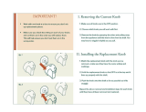
1. Remove the battery cover at the rear of the Console.
2. Place two "SIZE-AAA" batteries into the battery housing.
3. Insure the batteries are correctly positioned and the battery springs are in proper contact with
the batteries.
4. Re-install the battery cover.
NOTE:
1. When inactive for 3.5 minutes, the LCD display will automatically shut off.
2. To change displayed units from MPH to KMPH, hold the MODE key for 3 seconds. Doing this
will clear the ODOMETER.
3. To clear the workout data, press the RESET key. This will not clear data of ODOMETER. To
reset the ODOMETER, hold the MODE key for 3 seconds. This will change units from MPH to
KMPH, hold the MODE key for 3 seconds again to return to your desired units.
4. When there is activity, the console will automatically turn on.
5. If the display is illegible or is partially illegible, remove batteries and wait 15 seconds before
Reinstalling batteries then try again.
/