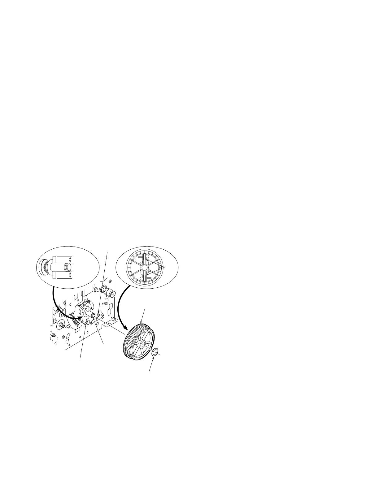
Sanyo DVP-P1 Datasheet

Category
Print & Scan
Type
Datasheet

This manual is also suitable for

1. SERVICE TOOLS ........................... 2
2. AN OVERVIEW OF THE
MECHANISM .................................. 3
2-1. Exploded view of the Unit .................. 3
2-2. Overview............................................ 5
2-3. Cam Drive.......................................... 5
2-4. Paper Advance Drive ......................... 6
2-5. Ink Ribbon Drive ................................ 7
2-6. Mechanism Mode Verification
Method............................................... 7
3. DISASSEMBLING THE MAIN
PARTS OF THE MECHANISM ....... 8
3-1. “MOTOR,FAN DC 1.8W”, “GUIDE,
INK-SVF01/EX”, and “LEVER,
CASSETTE STOPPER” .................... 8
3-2. S REEL ASSEMBLY .......................... 9
3-3. HEAD............................................... 10
3-4. PAPER EXIT ROLLER .................... 12
3-5. SUPPLY PAPER ROLLER .............. 12
3-6. “ASSY, MOTOR STEPPING”........... 14
Contents
3-7. RELAY PULLEY .............................. 14
3-8. “PULLEY,DRUM” ............................. 16
3-9. CAM MOTOR .................................. 16
3-10.“CHASSIS,SUB LOWER”................ 18
3-11. “COMPL,HOLDER,PINCH SIDE”,
“COMPL,HOLDER,PINCH PICK”,
“COMPL,HOLDER,PINCH EXIT F”,
and “COMPL,HOLDER,PINCH
EXIT” ............................................... 18
3-12.“SLIDE,LEVER TPH”....................... 20
3-13.“HOUSING,MOTOR FAN” and
“COMPL PWB,MC-6”....................... 20
3-14.“ASSY,CHASSIS R”, “COMPL, PIPE
DRUM RUBBER”, “COMPL,GUIDE,
PAPER”, “CAM,MECHANISM R”,
and “CAM,MECHANISM L” ............. 22
3-15.“GUIDE,CASSETTE R” and
“COMPL PWB,MC-3”....................... 24
3-16.“GUIDE,PAPER EXIT”, “COMPL
PWB,MC-4”, and “COMPL PWB,
MC-5”............................................... 24
3-17.“LEVER,TPH ADJUST”, “BEARING,
DRUM”, and “BEARING,DRUM” ..... 25
4. TROUBLESHOOTING.................. 26
4-1. The mechanism malfunctions when
the power is turned on. .................... 26
4-2. Poor printing quality......................... 26
4-3. Not printing ...................................... 27
4-4. Paper stopping ................................ 28
MECHANISM SERVICE
TECHNICAL INFORMATION
Digital Photo Printer
FILE NO.
REFERENCE No.MM5310544
SVF01/EX, U, C
DVP-P1EX
(Product code: 126 306 02)
DVP-P1
(Product code: 126 306 01)
DVP-P1C
(Product code: 126 306 03)
–2–
Fig.1-1-1
1. SERVICE TOOLS
VJ8-0225
No. 1
VJ8-0226, VJ8-0227
No. 2, 3
VJ8-0228
No. 4
VJ8-0229
No. 5
VHJ-0099
No. 6
No. Jig No. Quantity Parts name
1 VJ8-0225 1 Lever TPH adjusting tool
2 VJ8-0226 1 Dial tension gauge
3 VJ8-0227 1 Dial tension gauge
4 VJ8-0228 1 Ruler
5 VJ8-0229 1 Grease
6 VHJ-0099 1 Oil
–3–
2. AN OVERVIEW OF THE MECHANISM
2-1. Exploded view of the Unit
4I000
4B000
7B000
5F000
4E000
6N000
7Q000
6L000
6M000
7M000
7P000
6E000
6D000
6G000
6H000
03810
03800
5C000
4C000
4D000
1G000
5H000
6J000
6N000
6K000
6C000
6F000
6I000
2H000
MC-2
2C000
2B000
2A000
5M000
5H100
4F000
7L000
MC-6
2E000
2J000
2F000
4N000
4H000
4G100
4G200
4G300
4G400
4J000
Loc. No. Quantity Parts name
MC-2
1 COMPL PWB,MC-2
MC-6
1 COMPL PWB,MC-6
03800
1 GUIDE,INK-SVF01/EX
03810
3 SCR S-TPG BIN+W 2X5
1G000
1 SPECIAL WAHSER-3X0.5
2A000
1 COMPL,HOUSING REEL S
2B000
1 GEAR,RELAY PAPER EXIT
2C000
1 SCR S-TPG BIN 2.6X4
2E000
1 COMPL,HOUSING REEL T
2F000
1 SCR S-TPG BIN 2.6X4
2H000
1 SCR S-TPG BIN 2.6X4
2J000
1 CORD,TERMINAL
4B000
1 SPECIAL WASHER-7.1X0.8
4C000
2 WASHER Y 8X16X0.25
4D000
1 SPRING,PRESSURE DRUM
4E000
1 SHAFT,PULLEY FIX
4F000
1 PULLEY,DRUM
4G100
1 ASSY,LEVER,PULLEY
4G200
1 PULLEY,RELAY DRUM
4G300
1 STOPPER,BELT DRUM
4G400
1 SPECIAL WAHSER-3X0.5
4H000
1 SPECIAL SCREW-2.6X8
4I000
1 BELT,DRUM
4J000
1 BELT,MOTOR STEP
Loc. No. Quantity Parts name
4N000
1 SCR S-TPG BIN 2.6X3
5C000
1 SPECIAL WASHER-1.5X0.5
5F000
1 SPRING,PINCH ROLLER F
5H000
1 SPRING,PINCH ROLLER RB
5H100
1 SPRING,PINCH RELEASE
5M000
1 SLIDE,LEVER TPH
6C000
1 ASSY,ROLLER,EXIT GEAR
6D000
1 BEARING,SHAFT L
6E000
1 SPECIAL WASHER-2.5X0.5
6F000
1 ASSY,ROLLER,EXIT PULLEY
6G000
1 BEARING,SHAFT L
6H000
1 SPECIAL WASHER-2.5X0.5
6I000
1 BELT,PAPER EXIT
6J000
1 ASSY,ROLLER,PICK GEAR
6K000
1 GEAR,RELAY PICK UP
6L000
1 ARM,TRAY PAPER L
6M000
1 SPECIAL WASHER-3.5X0.5
6N000
2 SPRING,ARM TRAY PAPER
7B000
1 BEARING,DRUM
7L000
2 SCR S-TPG BIN 2.6X4
7M000
1 MOTOR,FAN DC 1.8W
7P000
2 SCR S-TPG BIN 3X12
7Q000
1 FIXER
NOTE: Items marked “(N.S.P.)” are not supplied.
–4–
6P300
6P300
3A000
1B000
1B000
1D000
1E000
1E000
1D000
5G000
7D000
7K000
5H100
5F000
4L000
4P000
4M000
4K000
7F000
7H000
7F000
7C000
7H000
7E000
6B000
3B200
3B100
6A000
3C000
5J000
7N000
7A000
7S000
5B000
5D000
5K000
5L000
5A000
5E000
1F000
1A000
1C000
1C000
1H000
1J000
6Q000
6Q000
6P100
MC-4
MC-1
MC-3
MC-5
5I000
7I000
7J000
7J000
4A000
3B200
5C000
4B000
A
B
E
F
D
C
F
E
B
D
C
A
G
G
Loc. No. Quantity Parts name
MC-1
1 COMPL PWB,MC-1
MC-3
1 COMPL PWB,MC-3
MC-4
1 COMPL PWB,MC-4
MC-5
1 COMPL PWB,MC-5
1A000
1 COMPL,HOLDER TPH
1B000
2 SPECIAL WASHER-3.5X0.3
1C000
2 SPRING,TPH HNG
1D000
2 LEVER,TPH ADJUST
1E000
2 SCR S-TPG BIN 2.6X4
1F000
1 ASSY,LEVER,TPH DOWN
1H000
1 SPRING,TPH CENTER
1J000
1 SPECIAL WASHER-4.2 X 0.3
3A000
1 LEVER,CASSETTE STOPPER
3B100
1 GUIDE,CASSETTE R
3B200
2 SCR S-TPG BIN 2.6X4
3C000
2 SCR S-TPG BIN 2.6X4
4A000
1 COMPL,PIPE DRUM RUBBER
4B000
1 SPECIAL WASHER-7.1X0.8
4K000
1 ASSY,MOTOR STEPPING
4L000
2 NUT HEX 3
4M000
4 GASKET,O RING(D2.8)
4P000
1 SPECIAL WASHER-4X0.3
5A000
1 COMPL,HOLDER,PINCH SIDE
5B000
1 COMPL,HOLDER,PINCH EXIT
5C000
1 SPECIAL WASHER-1.5X0.5
NOTE: Items marked “(N.S.P.)” are not supplied.
Loc. No. Quantity Parts name
5D000
1 COMPL,HOLDER,PINCH PICK
5E000
1 COMPL,HOLDER,PINCH EXIT F
5F000
1 SPRING,PINCH ROLLER F
5G000
1 SPRING,PINCH ROLLER LB
5H100
1 SPRING,PINCH RELEASE
5I000
1 COMPL,GUIDE,PAPER
5J000
1 ASSY,GEAR,CAM
5K000
1 CAM,MECHANISM L
5L000
1 CAM,MECHANISM R
6A000
1 COMPL,MOTOR CAM
6B000
1 SCR S-TPG BIN 2.6X4
6P100
1 GUIDE,PAPER EXIT
6P300
4 SCR S-TPG BIN 2.6X4
6Q000
4 SCR S-TPG BIN 2.6X4
7A000
1 ASSY,CHASSIS R (N.S.P.)
7C000
1 ASSY,CHASSIS L (N.S.P.)
7D000
1 BEARING,DRUM
7E000
1 CHASSIS,SUB LOWER
7F000
2 SCR S-TPG BIN 2.6X4
7H000
2 SCR S-TPG BIN 2.6X4
7I000
1 GUIDE,PAPER PICK
7J000
2 SCR S-TPG BIN 2.6X5
7K000
1 SCR S-TPG BIN 2.6X4
7N000
1 HOUSING,MOTOR FAN
7S000
1 ADHESIVE FAN HERNESS
–5–
2-2. Overview
The mechanism is run by the following three types of motors:
the “COMPL, MOTOR CAM
(6A000)
”, the “ASSY, MOTOR
STEPPING
(4K000)
”, and the “COMPL, HOUSING REEL T
(2E000)
”.
These motors are controlled by the CPU, which detects the
position of each movement by means of head position sensor
(Cam Sensor MC-1), ribbon encode sensor (Reel Sensor MC-
2), ribbon top sensor
(MC-3)
, paper top sensor
(MC-4)
, and
paper exit sensor
(MC-5)
, as explained in the “Circuit Move-
ment Details.”
2-3. Cam Drive
The cams (“CAM, MECHANISM L:
5K000
”; “CAM, MECHA-
NISM R:
5L000
”) are run by the “COMPL, MOTOR CAM
(6A000)
” through the following set mechanism modes: Standby
Paper exit Paper/Ribbon advance Pa-
per-supply
Print .
Chart 1 provides the Cam Drive related timing chart.
- The angle of revolution of the cam is detected by the
“COMPL PWB, MC-1” upper head position sensor (cam
sensor). The mechanism mode position is detected based
on the combined power output signals of S1, S2, and S3.
- The pressure and release of the head (“COMPL, HOLDER
TPH:
1A000
”).
- The setting of the paper guide (“COMPL, GUIDE, PAPER:
5I000
”), and the play of the head (“COMPL, HOLDER TPH:
1A000
”) when under pressure.
- The pressure and release of the non-paper-exit pinch rollers
(“COMPL, HOLDER, PINCH SIDE:
5A000
”, “COMPL,
HOLDER, PINCH PICK:
5D000
”, and “COMPL, HOLDER,
PINCH EXIT F:
5E000
”)
- The pressure and release of the paper-exit pinch roller
(“COMPL, HOLDER, PINCH EXIT:
5B000
”).
- The release and connection of the paper-supply gear
(“GEAR, RELAY PICK UP:
6K000
”).
- The locking and release of the S reel brake (“SLIDE, LEVER
TPH:
5M000
”).
Note 1: The Cam I.D. symbols are the numbers etched into
the “CAM,MECHANISM L
(5K000)
”.
Note 2: The code in letters and numbers in parentheses
indicate identifying Loc. No. in the Parts Price List.
Chart 1
Mode
Cam Symbol
Standby Paper Exit Paper/Ribbon Advance Paper Supply Print
Head Position
Sensor
(Cam sensor)
output
(Photoelectric
current
present: L)
(MC-1)
S1
S2
S3
Head Position
(1A000)
released
pressured
released
pressured
released
pressured
Head Pressure
(1A000)
fixed
play
Paper Guide
(5I000)
Non-paper-exit
Pinch Rollers
(5A000, 5D000,
5E000)
Paper-exit Pinch
Roller
(5B000)
released
in contact
released
locked
Paper-Supply
Gear
(6K000)
S Reel Brake
(5M000)
–6–
2-4. Paper Advance Drive
The stepping motor (“ASSY,MOTOR STEPPING:
4K000
”)
connects the timing belt (“BELT,MOTOR STEP:
4J000
”;
BELT,DRUM:
4I000
”), the “PULLEY,DRUM
(4F000)
”, and the
paper-supply gear (“GEAR,RELAY PICK UP:
6K000
”), drives
the “ASSY,ROLLER,PICK GEAR
(6J000)
” and starts the
supply of printing paper.
At this point, the paper guide (“ARM, PAPER, PICK”) of the
“COMPL,HOLDER,PINCH EXIT
(5B000)
” is lifted up and the
printing paper is sent to the platen (“COMPL,PIPE DRUM
RUBBER:
4A000
”).
The pulley drum (“PULLEY,DRUM:
4F000
”) is directly con-
nected to the shaft of the platen (“COMPL,PIPE DRUM RUB-
BER:
4A000
”) so the pulley drum (“PULLEY,DRUM:
4F000
”)
and the stepping motor (“ASSY,MOTOR STEPPING:
4K000
”)
rotate together.
Each of the pinch rollers (“COMPL,HOLDER,PINCH PICK:
5D000
”, “COMPL,HOLDER,PINCH SIDE:
5A000
”,
“COMPL,HOLDER,PINCH EXIT F:
5E000
”, “COMPL,
HOLDER,PINCH EXIT:
5B000
”) is pressing on the platen
(“COMPL,PIPE DRUM RUBBER:
4A000
”), so the supplied
printing paper is rolled onto the platen (“COMPL,PIPE DRUM
RUBBER:
4A000
”).
During printing, the printing paper proceeds in the order Y
(yellow)
M (magenta) C (cyan) OP (Over Print) making
a total of four revolutions.
After printing, the paper guide portion (“ARM PAPER PICK”) of
the “COMPL,HOLDER,PINCH EXIT
(5B000)
” descends, so
the printing paper is expelled by the platen (“COMPL,PIPE
DRUM RUBBER:
4A000
”) and the paper exit roller
(“ASSY,ROLLER,EXIT GEAR:
6C000
”, “ASSY,ROLLER,EXIT
PULLEY:
6F000
”).
Ordinarily, the stepping motor (“ASSY,MOTOR STEPPING:
4K000
”) revolves in the regular direction (counterclockwise
when looking at the mechanism from the right). The drive for
the paper exit rollers (“ASSY,ROLLER,EXIT GEAR:
6C000
”,
“ASSY,ROLLER,EXIT PULLEY:
6F000
”) is the stepping mo-
tor (“ASSY,MOTOR STEPPING:
4K000
”).
ON
ON
ON
ON
ON ON
ON
ON ON
ON
ON ON
ON
ON ON
ON
ON ON
ON
ON ON
ON
ON ON
ON
ON ON
ON ON
ON
ON
Paper top
sensor
(MC-4)
ASSY,
MOTOR
STEPPING
(4K000)
COMPL,
HOUSING
REEL T
(2E000)
COMPL,
MOTOR
CAM
(6A000)
Mecha-
nism
Mode
Paper
eject
sensor
(MC-5)
Ribbon
top sensor
(MC-3)
Ribbon
encode
sensor
(MC-2)
Head
position
sensor
(MC-1)
Ink type
sensor
(MC-6)
Printing Operations
Cassette verification
Ribbon slack taken up
Mechanism movement
Paper supply
Mechanism movement
Paper rolled on/ Y ribbon set
Mechanism movement
Yellow printing
Mechanism movement
Paper re-set/ M ribbon set
Mechanism movement
Magenta printing
Mechanism movement
Paper re-set/ C ribbon set
Mechanism movement
Cyan printing
Mechanism movement
Paper re-set/ OP ribbon set
Mechanism movement
Over printing
Mechanism movement/ribbon slack taken up
Paper ejected
Completed (Mechanism movement)
Chart 2
–7–
2-5. Ink Ribbon Drive
At the initiation of printing, the ribbon motor (“COMPL,HOUSING
REEL T:
2E000
”) starts up and the slack in the ribbon within
the cassette is taken up. At this time, the ribbon encoder
sensor (“COMPL PWB,MC-2:
MC-2
”) confirms that the slack
in the ribbon has been eliminated.
Next, the printing paper is supplied and, while the paper is
moving into the initial position for printing, the ribbon motor
(“COMPL,HOUSING REEL T:
2E000
”) operates and the ink
ribbon is wound to the beginning of the Y (yellow) ribbon. The
beginning position of the Y (yellow) ribbon is verified by the top
sensor (“COMPL PWB,MC-3:
MC-3
”).
During the yellow printing stage, the S side Reel Brake is
locked by the “SLIDE,LEVER TPH
(5M000)
”, and while
applying the appropriate tension to the ink ribbon, the ribbon is
rolled up.
Since the ink ribbon and the printing paper are held between
the head (“COMPL,HOLDER TPH:
1A000
”) and the platen
(“COMPL,PIPE DRUM RUBBER:
4A000
”) during the yellow
printing process, they are driven at a set speed by the stepping
motor (“ASSY,MOTOR STEPPING:
4K000
”).
Upon completion of the Y (yellow) printing process, when the
printing paper is returned to the initial position for printing, and
the ink ribbon is wound to the beginning of the M (magenta)
ribbon. The beginning position of the M (magenta) ribbon is
verified by the ribbon top sensor (“COMPL PWB,MC-3:
MC-3
”)
and the subsequent operations are carried out in the same
order as described for the Y (yellow) printing process. After
that, the C (cyan) and then the OP (over print) printing steps are
carried out, but the drive procedure is the same.
After the OP (over print) step, the ribbon slack is taken up
again.
2-6. Mechanism Mode Verification Method
By using a light source to illuminate the mechanism mode
verification hole of the “ASSY, CHASSIS L
(7C000)
”, the
numbers etched into the “CAM, MECHANISM L
(5K000)
” can
be verified.
ASSY,CHASSIS L
(7C000)
Mechanism Mode Verification Hole
Fig. 2-6-1
–8–
3. DISASSEMBLING THE MAIN PARTS
OF THE MECHANISM
POINTS TO NOTE
Referring to “3. HOW TO REMOVE THE CABINET PARTS”
in the Service Manual, remove the cabinet parts and the
circuit board assembly, and remove the Compl Mechanism.
The codes (letter and numbers in parentheses) indicate Loc.
No. in the parts list.
When fitting the parts of the mechanism, refer to the “Assem-
bly Notes”, and proceed in the reverse of the dis-assembly
order.
Clamps and dowels are used to prevent parts coming loose.
When removing a clamp or dowel, be careful not to force it,
as this can result in damage.
Since the dimension of the screw names in the figures are
subject to change without notice, always refer to the parts
list.
3-1. “MOTOR,FAN DC 1.8W
(7M000)
”,
“GUIDE,INK-SVF01/EX
(03800)
”, and
“LEVER,CASSETTE STOPPER
(3A000)
(See Figs. 3-1-1 to 3-1-2)
1) Remove the two “SCR S-TPG BIN 3X12
(7P000)
” and
remove the “MOTOR, FAN DC 1.8W
(7M000)
”. (Refer to
Fig. 3-1-1.)
2) Remove the cables from the hook on the “GUIDE, INK-
SVF01/EX
(03800)
” as shown in Fig. A of Fig. 3-1-1.
3) Remove the three “SCR S-TPG BIN+W 2X5
(03810)
” and
the “GUIDE,INK-SVF01/EX
(03800)
”. (Refer to Fig. 3-1-
1.)
4) Remove portion A on the “LEVER, CASSETTE STOP-
PER
(3A000)
” from hole on the “ASSY, CHASSIS L
(7C000)
” as shown in Fig. B of Fig. 3-1-2.
5) While rotating portion B on the “LEVER, CASSETTE
STOPPER
(3A000)
” upper side, remove it from hole on
the “ASSY, CHASSIS L
(7C000)
”. (Refer to Fig. 3-1-2.)
6) Pull portion C on the “LEVER, CASSETTE STOPPER
(3A000)
” out from hole on the “ASSY, CHASSIS L
(7C000)
” and remove the “LEVER, CASSETTE STOP-
PER
(3A000)
”. (Refer to Fig. 3-1-2.)
ASSEMBLY NOTES:
1. Insert the two dowels on the “GUIDE, INK-SVF01/EX
(03800)
” into holes on the “ASSY, CHASSIS L
(7C000)
”,
and install the “GUIDE, INK-SVF01/EX
(03800)
” by
sliding it upwards. (Refer to Fig. 3-1-1.)
2. Place portion D on the “LEVER, CASSETTE STOPPER
(3A000)
” in the reverse side of portion E on the “LEVER,
TPH ADJUST
(1D000)
” as shown in Fig. B of Fig. 3-1-2,
and verify that the “LEVER, TPH ADJUST
(1D000)
moves smoothly by flicking it.
SCR S-TPG BIN+W
2X5
(03810)
SCR S-TPG BIN 3X12
(7P000)
MOTOR,FAN DC 1.8W
(7M000
)
GUIDE,INK-SVF01/EX
(03800)
GUIDE,INK-SVF
01/EX
(03800)
ASSY,CHASSIS L
(7C000)
Hook
Cable
Dowel
Holes
Dowel
Fig. A
Fig. 3-1-1
LEVER,CASSETTE
STOPPER
(3A000)
ASSY,
CHASSIS L
(7C000)
ASSY,
CHASSIS L
(7C000)
LEVER,CASSETTE
STOPPER
(3A000)
Fig. B
Portion A
Portion B
Portion D
Portion C
Portion E
LEVER,TPH
ADJUST
(1D000)
Fig. 3-1-2
–9–
3-2. S REEL ASSEMBLY
(See Figs. 3-2-1 to 3-2-2)
3-2-1. “BELT, PAPER EXIT
(6I000)
”, “COMPL,
HOUSING REEL S
(2A000)
”, “GEAR,
RELAY PAPER EXIT
(2B000)
”, and
“COMPL PWB, MC-2
(MC-2)
1) Remove the “BELT, PAPER EXIT
(6I000)
”. (Refer to Fig.
3-2-1.)
2) Remove the “SCR S-TPG BIN 2.6X4
(2H000)
” and
remove the “COMPL PWB,MC-2
(MC-2)
”. (Refer to Fig.
3-2-2.)
3) Remove the “SCR S-TPG BIN 2.6X4
(2C000)
”. (Refer to
Fig. 3-2-2.)
4) Remove the “COMPL, HOUSING REEL S
(2A000)
”.
(Refer to Fig. 3-2-2.)
5) Remove the “GEAR, RELAY PAPER EXIT
(2B000)
”.
(Refer to Fig. 3-2-2.)
ASSEMBLY NOTES:
1. After cleaning shaft 1, apply oil (VHJ-0099) around it.
(Refer to Fig. 3-2-2.)
2. Insert portion A on the “COMPL, HOUSING REEL S
(2A000)
” into hole on the “ASSY, CHASSIS R
(7A000)
”,
as shown in Fig. A of Fig. 3-2-2.
3. Align dowel 1 on the “ASSY, CHASSIS R
(7A000)
” with
hole 1 on the “COMPL, HOUSING REEL S
(2A000)
”.
(Refer to Fig. 3-2-2.)
4. Install the “BELT, PAPER EXIT
(6I000)
” without bending.
BELT,PAPER
EXIT
(6I000)
ASSY,CHASSIS R
(7A000)
Fig. 3-2-1
SCR S-TPG BIN
2.6X4
(2C000)
SCR S-TPG BIN
2.6X4
(2H000)
COMPL PWB,MC-2
(MC-2)
GEAR,RELAY
PAPER EXIT
(2B000)
COMPL,HOUSING REEL S
(2A000)
ASSY,CHASSIS R
(7A000)
Fig. A
Hole 1
Dowel 1
Shaft 1
Portion A
Fig. 3-2-2
–10–
3-3. HEAD
(See Figs. 3-3-1 to 3-3-3)
3-3-1. “COMPL, HOUSING REEL T
(2E000)
”,
“CORD, TERMINAL
(2J000)
”, “ASSY,
LEVER, TPH DOWN
(1F000)
”, and
“COMPL PWB, MC-1
(MC-1)
1) Referring to section 3-1, remove the “MOTOR, FAN DC
1.8W
(7M000)
”.
2) Remove the “SCR S-TPG BIN 2.6X4
(2F000)
” and
remove the “CORD, TERMINAL
(2J000)
”. (Refer to Fig.
3-3-1.)
3) Remove the “COMPL, HOUSING REEL T
(2E000)
”.
(Refer to Fig. 3-3-1.)
4) Remove the “SPECIAL WAHSER-3X0.5
(1G000)
”. (Re-
fer to Fig. 3-3-1.)
5) Remove dowel 1 on the “ASSY, LEVER,TPH DOWN
(1F000)
” from hole 1 on the “ASSY, CHASSIS R
(7A000)
”.
(Refer to Fig. 3-3-2.)
NOTE: When carrying out steps 5) - 8), be careful not to
injure the surface of the head by pressing down too hard
on the “COMPL,HOLDER TPH
(1A000)
” shown in Fig. 3-
2-2. To prevent injury to the surface of the head, insert
printing paper (approx. 100mm wide x 148mm long) from
the ink ribbon slot.
6) Insert dowel 1 side of portion A on the “ASSY, LEVER,
TPH DOWN
(1F000)
” into hole 2 on the “ASSY, CHASSIS
R
(7A000)
” as shown in Fig. B of Fig. 3-3-2.
7) While press the “ASSY, LEVER, TPH DOWN
(1F000)
approximately 2mm to the “ASSY, CHASSIS R
(7A000)
” side, pull hole 3 on the “ASSY, LEVER, TPH
DOWN
(1F000)
” out from shaft 2 on the “ASSY, CHAS-
SIS L
(7C000)
”. (Refer to Fig. 3-3-2.)
8) Be careful not to distort the “ASSY, CHASSIS R” and pull
portion A out from hole 2 and remove the “ASSY, LEVER,
TPH DOWN
(1F000)
”. (Refer to Fig. 3-3-2.)
9) Disconnect the connector from the “COMPL PWB, MC-1
(MC-1)
”.
10) Remove the “SCR S-TPG BIN 2.6X4
(7K000)
” and
remove the “COMPL PWB, MC-1
(MC-1)
”. (Refer to Fig.
3-3-2.)
NOTE: It is unnecessary to remove the “COMPL PWB,
MC-1
(MC-1)
” to replace the “COMPL, HOLDER TPH
(1A000)
”.
ASSEMBLY NOTES:
1. Insert portion B on the “COMPL, HOUSING REEL T
(2E000)
” into hole on the “ASSY, CHASSIS R
(7A000)
as shown in Fig. A of Fig. 3-3-1.
2. Align hole 3 with shaft 2 on the “ASSY, CHASSIS L
(7C000)
”. Align dowel 1 with hole 1 on the “ASSY,
CHASSIS R
(7A000)
”. Align shaft 1 with slot 1 on the
“SLIDE, LEVER TPH
(5M000)
”. (Hole 3, dowel 1, and
shaft 1 are on the “ASSY, LEVER, TPH DOWN
(1F000)
”).
Be careful not to distort the “ASSY, CHASSIS R/L” and
install the “ASSY, LEVER, TPH DOWN
(1F000)
”.
SSCR S-TPG BIN
2.6X4
(2F000)
SPECIAL
WAHSER-3X0.5
(1G000)
ASSY, CHASSIS R
(7A000)
CORD,TERMINAL
(2J000)
COMPL,HOUSING
REEL T
(2E000)
Fig. A
Hole
Portion B
Fig. 3-3-1
ASSY,LEVER,TPH DOWN
(1F000)
ASSY,CHASSIS R
(7A000)
ASSY,CHASSIS L
(7C000)
SCR S-TPG BIN 2.6X4
(7K000)
COMPL PWB,MC-1
(MC-1)
Fig. B
Dowel 1
SLIDE,LEVER
TPH
(5M000)
COMPL,HOLDER
TPH
(1A000)
Dowel 2
Shaft 1
Portion A
Shaft 2
Ink ribbon
slot
Hole 2
Hole 2
Hole 3
Slot 1
Hole 1
Connector
While turning the
“ASSY, LEVER, TPH
DOWN
(1F000)
”, insert
its dowel 1 side slightly
into hole 2.
Fig. 3-3-2
–11–
3-3-2. “COMPL,HOLDER TPH
(1A000)
1) Remove the two “SPECIAL WASHER-3.5X0.3
(1B000,
1J000)
”. (Refer to Fig. 3-3-3.)
2) To prevent injury to the surface of the head due to
dropping it, insert printing paper (approx. 100mm wide x
148mm long) under the “COMPL, HOLDER TPH
(1A000)
from the ink ribbon slot.
3) To prevent the “COMPL, HOLDER TPH
(1A000)
” from
falling down, remove the two “SPRING, TPH HNG
(1C000)
while holding the “COMPL, HOLDER TPH
(1A000)
”.
4) Pull shaft 2 out while pressing the “COMPL, HOLDER
TPH
(1A000)
” approximately 2mm to the “ASSY, CHAS-
SIS R
(7A000)
” side.
5) Insert portion D on into the ink ribbon slot as shown in
Fig. C.
6) Pull shaft 3 on the “COMPL, HOLDER TPH
(1A000)
” the
out from hole 4 and remove it. Remove shaft 3 in the
direction of the arrow as shown in Fig. D.
NOTE: Be careful that the “ASSY, CHASSIS” is not
transformed. Be careful not to touch the surface of the
head on the “COMPL, HOLDER TPH
(1A000)
”.
7) Remove the “SPRING, TPH CENTER
(1H000)
” and
“SPECIAL WASHER-4.2 X 0.3
(1J000)
”.
ASSEMBLY NOTES:
1. After replacing the “COMPL, HOLDER TPH
(1A000)
”, be
sure to refer to the “Adjustment of Circuit” section in the
Service Manual and perform “4-1. Adjustment of Thermal
Printer Head Resistance Value”.
COMPL,HOLDER
TPH
(1A000)
SPRING,TPH HNG
(1C000)
SPRING,
TPH
CENTER
(1H000)
SPECIAL WASHER-
4.2 X 0.3
(1J000)
SPECIAL
WASHER-
3.5X0.3
(1B000)
LEVER,TPH
ADJUST
(1D000)
SPECIAL
WASHER-
3.5X0.3
(1B000)
ASSY,CHASSIS R
(7A000)
Fig. C
Fig. D
Hole 4
Shaft 2
Ink ribbon slot
Shaf 3
Head
Portion D
Shaft 3
Fig. 3-3-3
–12–
3-4. PAPER EXIT ROLLER
(See Figs. 3-4-1 to 3-4-3)
3-4-1. “BELT, PAPER EXIT
(6I000)
”, “ASSY,
ROLLER, EXIT PULLEY
(6F000)
”, and
“ASSY, ROLLER, EXIT GEAR
(6C000)
1) Referring to section 3-1, remove the “GUIDE, INK-SVF01/
EX
(03800)
”.
2) Remove the “BELT, PAPER EXIT
(6I000)
”. (Refer to Fig.
3-4-1.)
3) Remove the “SPECIAL WASHER-2.5X0.5
(6H000)
”.
(Refer to Fig. 3-4-2.)
4) Pull the “ASSY, ROLLER, EXIT PULLEY
(6F000)
” out as
shown in Fig. 3-4-3 and remove the “BEARING, SHAFT
L
(6D000)
” on the upper side as shown in Fig. 3-4-2.
NOTE: Do not injure the rubber roller portions on the
“ASSY, ROLLER, EXIT PULLEY
(6F000)
” when pulling
it out from the “ASSY, CHASSIS R
(7A000)
”.
5) Remove the “SPECIAL WASHER-2.5X0.5
(6E000)
”.
(Refer to Fig. 3-4-2.)
6) Pull the “ASSY, ROLLER, EXIT GEAR
(6C000)
” out as
shown in Fig. 3-4-3 and remove the “BEARING, SHAFT
L
(6D000)
” on the lower side as shown in Fig. 3-4-2.
NOTE: Do not injure the rubber roller portions on the
“ASSY, ROLLER, EXIT GEAR
(6C000)
” when pulling it
out from the “ASSY, CHASSIS R
(7A000)
”.
ASSEMBLY NOTES:
1. Do not injure the rubber roller portions on the “ASSY,
ROLLER, EXIT GEAR
(6C000)
” and the “ASSY, ROLLER,
EXIT PULLEY
(6F000)
” when installing them into the
“ASSY, CHASSIS”.
2. Align portion A on the “ASSY, ROLLER, EXIT PULLEY
(6F000)
” and portion B on the “ASSY, ROLLER, EXIT
GEAR
(6C000)
” with holes on the “ASSY, CHASSIS R
(7A000)
” as shown in Fig. B of Fig. 3-4-3.
3. Install the two “BEARING, SHAFT L
(6D000)
” so that they
align with the each of the holes on the “ASSY, CHASSIS
R
(7A000)
” as shown in Fig. A of Fig. 3-4-2.
4. Install the “BELT, PAPER EXIT
(6I000)
” without the
bending.
BELT,PAPER EXIT
(6I000
)
Fig. 3-4-1
SPECIAL WASHER-2.5X0.5
(6H000)
SPECIAL WASHER-2.5X0.5
(6E000)
BEARING,SHAFT L
(6D000)
Fig. A
Fig. 3-4-2
ASSY,ROLLER,
EXIT GEAR
(6C000)
ASSY,ROLLER,
EXIT PULLEY
(6F000)
ASSY,CHASSIS R
(7A000)
Align
Portion B
Portion A
Rubber roller portions
Fig. B
Fig. 3-4-3
3-5. SUPPLY PAPER ROLLER
(See Figs. 3-5-1 to 3-5-3)
3-5-1. “ASSY, ROLLER, PICK GEAR
(6J000)
”,
“GUIDE, PAPER PICK
(7I000)
”, “GEAR,
RELAY PICK UP
(6K000)
”, and “ARM,
TRAY PAPER L
(6L000)
1) After remove the two “SCR S-TPG BIN 2.6X5
(7J000)
and the two “SPRING, PINCH RELEASE
(5H100)
”,
remove the “GUIDE ,PAPER PICK
(7I000)
”. (Refer to Fig.
3-5-2.)
–13–
2) Remove the two “SPRING, ARM TRAY PAPER
(6N000)
”.
(Refer to Fig. 3-5-1 and Fig. 3-5-3.)
3) Remove the “SPECIAL WASHER-3.5X0.5
(6M000)
”.
(Refer to Fig. 3-5-1.)
4) Remove the “ASSY,ROLLER,PICK GEAR
(6J000)
”. (Re-
fer to Fig. 3-5-3.)
NOTE: Do not injure the rubber roller portion on the
“ASSY, ROLLER,PICK GEAR
(6J000)
” when pulling it
out from the “ASSY, CHASSIS R
(7A000)
”.
5) Remove the “GEAR, RELAY PICK UP
(6K000)
”. (Refer
to Fig. 3-5-3.)
6) Remove the “ARM, TRAY PAPER L
(6L000)
”. (Refer to
Fig. 3-5-1.)
ASSEMBLY NOTES:
1. Align dowel 1 with hole 1 on the “ASSY, CHASSIS L
(7C000)
” and install the “ARM, TRAY PAPER L
(6L000)
as shown in Fig. 3-5-1.
2. Install the “SPRING, ARM TRAY PAPER
(6N000)
” as
shown in Fig. C of Fig. 3-5-1.
3. Pay attention to the direction of installation of the “GEAR,
RELAY PICK UP
(6K000)
” and install it on the “ASSY,
ROLLER, PICK GEAR
(6J000)
” as shown in Fig. E of Fig.
3-5-3.
4. Align dowel 2 with hole 2 and install the “GEAR, RELAY
PICK UP
(6K000)
” to the “ASSY, CHASSIS R
(7A000)
as shown in Fig. 3-5-3. At that time, be careful that dowel
2 is not placed over the “CAM, MECHANISM R
(5L000)
”.
5. Install the “SPRING, ARM TRAY PAPER
(6N000)
” as
shown in Fig. D of Fig. 3-5-3.
6. Insert and hook the long end of the “SPRING, PINCH
RELEASE
(5H100)
” between washer and arm plate, and
hook the short end onto the “GUIDE, PAPER PICK
(7I000)
” as shown in Figs. A and B of Fig. 3-5-2.
7. Do not injure the rubber roller portion on the “ASSY,
ROLLER, PICK GEAR
(6J000)
” when inserting it into hole
on the “ASSY, CHASSIS”.
SPECIAL
WASHER-3.5X0.5
(6M000)
ARM,TRAY PAPER L
(6L000)
SPRING,ARM TRAY
PAPER
(6N000)
Hole 1
Fig. C
Dowel 1
ASSY,CHASSIS L
(7C000)
Fig. 3-5-1
SPRING,PINCH RELEASE
(5H100)
SPRING,
PINCH
RELEASE
(5H100)
GUIDE,PAPER PICK
(7I000)
SCR S-TPG BIN
2.6X5
(7J000)
Washer
Washer
Fig. A
Shaft
Arm Arm
Shaft
Fig. B
Fig. 3-5-2
GEAR,RELAY
PICK UP
(6K000)
GEAR,RELAY PICK UP
(6K000)
ASSY,ROLLER,PICK
GEAR
(6J000)
SPRING,ARM TRAY PAPER
(6N000)
ASSY,ROLLER,PICK GEAR
(6J000)
CAM,MECHANISM R
(5L000)
ASSY,CHASSIS R
(7A000)
Fig. D
Hole 2
Dowel 2
Rubber roller
portion
Fig. E
Fig. 3-5-3
–14–
3-6. “ASSY, MOTOR STEPPING
(4K000)
(See Figs. 3-6-1 to 3-6-3)
1) Disconnect the connector on the “ASSY, MOTOR STEP-
PING
(4K000)
”. (Refer to Fig. 3-6-1.)
2) Remove the two “NUT HEX 3
(4L000)
” ((A) and (B)) and
remove the “ASSY, MOTOR STEPPING
(4K000)
”. (Re-
fer to Fig. 3-6-1.)
NOTE: Take care not to lose the “SPECIAL WASHER-
4X0.3
(4P000)
” when removing the “NUT HEX 3
(4L000)
”.
Take care not to lose the four “GASKET, O RING(D2.8)
(4M000)
” when removing the “ASSY, MOTOR STEP-
PING
(4K000)
”.
ASSEMBLY NOTES:
1. Referring to Fig. 3-6-2, install the “ASSY, MOTOR STEP-
PING
(4K000)
” according to the following procedure.
a. Hook the “BELT, MOTOR STEP
(4J000)
” to the
“ASSY, MOTOR STEPPING
(4K000)
” and tighten the
two “NUT HEX 3
(4L000)
” at the point where the
“BELT, MOTOR STEP
(4J000)
” stretches tightly.
b. Referring to section 3-7, confirm that the adjustment
tension value of the “BELT, DRUM
(4I000)
” is correct.
c. Rotating the “PULLEY, DRUM
(4F000)
” clockwise,
rotate the “BELT, MOTOR STEP
(4J000)
” more than
one revolution.
d. Set the Ruler (VJ8-0228) along the “BELT, MOTOR
STEP
(4J000)
”, confirm that the pressure welding
value is [0.34N±0.15N] when pressing the Dial Ten-
sion Gauge DTN-100G (VJ8-0227) until the play in the
“BELT, MOTOR STEP
(4J000)
” is 0.5mm. The mea-
suring position and the direction of pressure on the
“BELT, MOTOR STEP
(4J000)
” are shown in Fig. 3-
6-3.
e. If the pressure welding value is not [0.34N±0.15N],
loosen the “NUT HEX 3
(4L000)
” (B) and fine-adjust
the “ASSY, MOTOR STEPPING
(4K000)
”, then re-
tighten the “NUT HEX 3
(4L000)
” (B) again.
f. Repeat steps c, d, and e above until the pressure
welding value is within [0.34N±0.15N].
SPECIAL
WASHER-4X0.3
(4P000)
NUT HEX 3
(4L000)
(A)
NUT HEX 3
(4L000)
(B)
GASKET,O RING(D2.8)
(4M000)
GASKET,
O RING(D2.8)
(4M000)
ASSY,MOTOR
STEPPING
(4K000)
Connector
Fig. 3-6-1
Dial tension gauge
DTN-100G
(VJ8-0227)
Ruler (VJ8-0228)
BELT,MOTOR STEP
(4J000)
PULLEY,DRUM
(4F000)
NUT HEX 3
(4L000)
BELT,DRUM
(4I000)
Fig. 3-6-2
Bending
value 0.5mm
ASSY,MOTOR
STEPPING
(4K000)
BELT,MOTOR
STEP
(4J000)
PULLEY,RELAY DRUM
(4G200)
PULLEY,DRUM
(4F000)
BELT,DRUM
(4I000)
Position of measuring tension
Fig. 3-6-3
3-7. RELAY PULLEY
(See Figs. 3-7-1 to 3-7-3)
3-7-1. “BELT,MOTOR STEP
(4J000)
”, “BELT,
DRUM
(4I000)
”, “ASSY, LEVER, PULLEY
(4G100)
”, and “PULLEY, RELAY DRUM
(4G200)
1) Remove the “SPECIAL SCREW-2.6X8
(4H000)
” and the
“SCR S-TPG BIN 2.6X3
(4N000)
”. (Refer to Fig. 3-7-2.)
2) Remove the “BELT,MOTOR STEP
(4J000)
” and the
“BELT,DRUM
(4I000)
”. (Refer to Fig. 3-7-2.)
3) Remove the “ASSY,LEVER,PULLEY
(4G100)
”. (Refer to
Fig. 3-7-2.)
4) Remove the “SPECIAL WAHSER-3X0.5
(4G400)
” and
the “STOPPER,BELT DRUM
(4G300)
”. (Refer to Fig. 3-
7-2.)
5) Remove the “PULLEY,RELAY DRUM
(4G200)
”. (Refer
to Fig. 3-7-2.)
–15–
ASSEMBLY NOTES:
1. Install the “PULLEY,RELAY DRUM
(4G200)
” and the
“STOPPER, BELT DRUM
(4G300)
” to the “ASSY, LE-
VER, PULLEY
(4G100)
” with the “SPECIAL WAHSER-
3X0.5
(4G400)
”.
Turn the raised side of the “STOPPER,BELT DRUM
(4G300)
” toward the “PULLEY, DRUM
(4F000)
” as
shown in Fig. B of Fig. 3-7-2.
2. Insert portion A into hole 1 and initially install the “ASSY,
LEVER, PULLEY
(4G100)
” using the “SCR S-TPG BIN
2.6X3
(4N000)
” as shown in Fig. A of Fig. 3-7-2.
3. Referring to Fig. 3-7-3, adjust the pressure welding value
and install the “ASSY,LEVER,PULLEY
(4G100)
” as
follows:
a. Hook the “BELT, DRUM
(4I000)
” and the “BELT,
MOTOR STEP
(4J000)
” on the gears, and tighten the
“SPECIAL SCREW-2.6X8
(4H000)
” and the “SCR S-
TPG BIN 2.6X3
(4N000)
” at the point where both belts
stretch tightly.
b. Rotating the “PULLEY, DRUM
(4F000)
” clockwise,
rotate the “BELT, DRUM
(4I000)
” more than one
revolution.
c. Set the Ruler (VJ8-0228) along the “BELT,DRUM
(4I000)
”, and confirm that the pressure welding value
is [1.34N±0.29N] when pressing the Dial Tension
Gauge DTN-150G (VJ8-0226) until play in the
“BELT,DRUM
(4I000)
” is 1mm. The measuring posi-
tion and the direction of pressure are shown in Fig. 3-
7-1.
d. If the pressure welding value is not [1.34N±0.29N],
loosen the “SPECIAL SCREW-2.6X8
(4H000)
” and
fine-adjust the “ASSY,LEVER,PULLEY
(4G100)
”,
then re-tighten the “SPECIAL SCREW-2.6X8
(4H000)
”. Repeat steps b and c above until the
pressure welding value is within [1.34N±0.29N].
e. Referring to section 3-6, adjust the tension of the
“BELT,MOTOR STEP
(4J000)
”.
PULLEY,DRUM
(4F000)
PULLEY,RELAY DRUM
(4G200)
BELT,MOTOR
STEP
(4J000)
ASSY,MOTOR
STEPPING
(4K000)
BELT,DRUM
(4I000)
Bending value
1mm
Position of measuring tension
Bending
value
0.5mm
Fig. 3-7-1
SCR S-TPG BIN
2.6X3
(4N000)
ASSY,LEVER,PULLEY
(4G100)
SPECIAL SCREW-2.6X8
(4H000)
PULLEY,RELAY
DRUM
(4G200)
STOPPER,BELT
DRUM
(4G300)
SPECIAL
WAHSER-
3X0.5
(4G400)
SPECIAL
WAHSER-
3X0.5
(4G400)
BELT,MOTOR
STEP
(4J000)
BELT,DRUM
(4I000)
Fig. A
Fig. B
Hole 1
Portion A
STOPPER,BELT
DRUM
(4G300)
Turn the raised side toward
the “PULLEY,DRUM
(4F000)
”.
Fig. 3-7-2
Dial tension gauge
DTN-150G
(VJ8-0226)
Ruler
(VJ8-0228)
ASSY,LEVER,PULLEY
(4G100)
SPECIAL SCREW-2.6X8
(4H000)
BELT,DRUM
(4I000)
PULLEY,DRUM
(4F000)
Fig. 3-7-3
–16–
3-8. “PULLEY,DRUM
(4F000)
(See Fig. 3-8-1)
1) Referring to section 3-2, remove the “COMPL,HOUSING
REEL S
(2A000)
”.
2) Referring to section 3-5, remove the “ARM,TRAY PAPER
L
(6L000)
”.
3) Referring to section 3-7, remove the “SPECIAL WAHSER-
3X0.5
(4G400)
” and the “STOPPER,BELT DRUM
(4G300)
”, and remove the “BELT,DRUM
(4I000)
”.
4) Remove the “SPECIAL WASHER-7.1X0.8
(4B000)
” and
remove the “PULLEY,DRUM
(4F000)
”.
ASSEMBLY NOTES:
1. Apply grease (VJ8-0229) to portion A as shown in Fig. 3-
8-1.
2. Adjust the “SHAFT,PULLEY FIX
(4E000)
” so that the
length of portion B and portion C measured look to be
equal as shown in Fig. A.
3. Place the “PULLEY,DRUM
(4F000)
” so that the slots on
its reverse side are aligned with and enter the “SHAFT,
PULLEY FIX
(4E000)
” as shown in Fig. B.
4. While pressing the top of the opposite side of shaft 1, push
the “PULLEY,DRUM
(4F000)
” on to shaft 1 and install the
“SPECIAL WASHER-7.1X0.8
(4B000)
”.
5. Referring to section 3-6, adjust the tension of the
“BELT,MOTOR STEP
(4J000)
”.
6. Referring to section 3-7, adjust the tension of the
“BELT,DRUM
(4I000)
”.
SHAFT,PULLEY FIX
(4E000)
PULLEY,DRUM
(4F000)
SPECIAL WASHER-7.1X0.8
(4B000)
Fig. A
Shaft 1
Portion A
Slots
Portion B
Portion C
Fig. B
Fig. 3-8-1
3-9. CAM MOTOR
(See Figs. 3-9-1 to 3-9-4)
3-9-1. “COMPL,MOTOR CAM
(6A000)
” and
“ASSY,GEAR,CAM
(5J000)
1) Referring to section 3-6, remove the “ASSY,MOTOR
STEPPING
(4K000)
”.
2) Rotate the worm gear on the “COMPL,MOTOR CAM
(6A000)
” until the indication shown in the mechanism
mode verification hole becomes [1]. (For the location of
the mechanism mode verification hole, refer to Fig. 3-9-2.)
NOTE: Rotating in direction A moves the numeral up and
direction B moves it down as shown in Fig. A
3) Remove the “SCR S-TPG BIN 2.6X4
(6B000)
”. (Refer to
Fig. 3-9-1.)
4) Release the cable on the “COMPL,MOTOR CAM
(6A000)
from the hooks on the “GUIDE,CASSETTE R
(3B100)
”.
5) Remove the “FIXER
(7Q000)
”.
6) While pushing the “COMPL,MOTOR CAM
(6A000)
” in
the direction of the arrow A with a screwdriver, slide it in
the direction of the arrow B and remove as shown in Fig.
B of Fig. 3-9-1.
NOTE: Be careful that the “ASSY,CHASSIS L
(7C000)
is not distorted.
7) Remove the “ASSY,GEAR,CAM
(5J000)
”.
ASSEMBLY NOTES:
1. Install the “ASSY,GEAR,CAM
(5J000)
” in the designated
position, move gear on the “ASSY,CHASSIS L
(7C000)
side approximately 5mm in the direction C as shown in
Fig. H of Fig. 3-9-3 and hold it with your right hand.
2. Rotate the gear with your forefinger in the direction D
(“CAM,MECHANISM R
(5L000)
” rotates too) as shown in
Fig. H of Fig. 3-9-3. Then press portion F on the
“CAM,MECHANISM R
(5L000)
” against the shaft on the
“COMPL,HOLDER,PINCH EXIT
(5B000)
” as shown in
Fig. G of Fig. 3-9-3.
3. While keeping the state in step 2 above, rotate the
“CAM,MECHANISM L
(5K000)
” with your finger and
press portion E on it against the shaft of the “COMPL,
HOLDER,PINCH EXIT
(5B000)
” as shown in Fig. F of Fig.
3-9-3.
4. While keeping the state in steps 2 and 3 above, install
shaft 1 on the “ASSY,GEAR,CAM
(5J000)
” into slot 1 on
the “ASSY,CHASSIS L
(7C000)
” without a gap. (Refer to
Fig. H of Fig. 3-9-3.)
5. Keep the state in step 4 above so that there are no gaps
between the gears on either side of the “ASSY,GEAR,CAM
(5J000)
”, the gears on the “CAM,MECHANISM L
(5K000)
and the “CAM,MECHANISM R
(5L000)
”.
6. Install the “COMPL,MOTOR CAM
(6A000)
” so that por-
tion A, portion B and portion C align accurately with the
dowels as shown in Fig. C, Fig. D and Fig. E of Fig. 3-9-
2, and tighten the “SCR S-TPG BIN 2.6X4
(6B000)
”.
7. Referring Fig. A of Fig. 3-9-1, rotate the worm gear on the
“COMPL,MOTOR CAM
(6A000)
” in direction A with your
finger. Then place one end of the shaft of the “COMPL,
HOLDER,PINCH EXIT
(5B000)
” onto portion G of the
“CAM,MECHANISM L
(5K000)
” and the other end onto
portion H of the “CAM, MECHANISM R
(5L000)
” as
shown in Fig. 3-9-4.
8. Referring Fig. A of Fig. 3-9-1, rotate the worm gear on the
“COMPL,MOTOR CAM
(6A000)
” in direction B with your
finger, and verify that the shafts on either side of the
“COMPL, HOLDER,PINCH EXIT
(5B000)
” slip down at
the same time. If the “CAM,MECHANISM R
(5L000)
” and
–17–
the “CAM,MECHANISM L
(5K000)
” are aligned correctly,
the shafts on either side of the “COMPL, HOLDER,PINCH
EXIT
(5B000)
” will slip down at the same time. If not
correctly aligned, the timing of the shaft drop will be off.
9. If, on completion of step 8, the Cam Mechanism is out of
phase, repeat steps 1 to 8.
10. Upon completion of installing the “COMPL,MOTOR CAM
(6A000)
” correctly, rotate the worm gear on it until the
indication shown in the mechanism mode verification hole
become [1].
11. Referring to section 3-6, adjust the tension of the
“BELT,MOTOR STEP
(4J000)
”.
COMPL,MOTOR CAM
(6A000)
ASSY,GEAR,
CAM
(5J000)
SCR S-TPG BIN
2.6X4
(6B000)
A
B
FIXER
(7Q000)
Fig. A
Portion A
Arrow B
Arrow A
Push
Hooks on the
“GUIDE,
CASSETTE R
(3B100)
Fig. B
Worm gear
Fig. 3-9-1
COMPL,MOTOR
CAM
(6A000)
Fig. E
Fig. D
Portion A
Portion B
Portion C
Fig. C
Dowel
Dowel
Dowel
Mechanism Mode Verification Hole
Fig. 3-9-2
CAM,MECHANISM L
(5K000)
Fig. F
Portion F
Portion E
Front side
Front side
Fig. G
Fig. H
ASSY,CHASSIS L
(N.S.P.)
(7C000)
ASSY,GEAR,CAM
(5J000)
CAM,MECHANISM R
(5L000)
C
D
Shaft of the
“COMPL,HOLDER,
PINCH EXIT
(5B000)
CAM,
MECHANISM
L
(5K000)
Shaft of the
“COMPL,HOLDER,
PINCH EXIT
(5B000)
CAM,
MECHANISM
R
(5L000)
HoleHole
Slot1
Shaft1
Note: Fig. F and Fig. G
are bottom views of the
mechanism.
Fig. 3-9-3
Shaft of the
“COMPL,HOLDER,
PINCH EXIT
(5B000)
Shaft of the “COMPL,
HOLDER,PINCH EXIT
(5B000)
Note: Fig. 3-9-4 is bottom views of the mechanism.
Portion H of the
“CAM,MECHANISM R
(5L000)
Portion G of the
“CAM,MECHANISM L
(5K000)
Fig. 3-9-4
–18–
3-10. “CHASSIS,SUB LOWER
(7E000)
(See Fig. 3-10-1)
1) Referring to section 3-7, remove the “ASSY, LEVER,
PULLEY
(4G100)
” and the “PULLEY, RELAY DRUM
(4G200)
”.
2) Remove the two “SCR S-TPG BIN 2.6X4
(7F000)
” and
remove the “CHASSIS,SUB LOWER
(7E000)
”.
ASSEMBLY NOTES:
1. Install the “CHASSIS,SUB LOWER
(7E000)
” so that
portions A and B hook onto the “ASSY,CHASSIS R
(7A000)
” and the “ASSY,CHASSIS L
(7C000)
” respec-
tively as shown in Fig. A and Fig. B.
2. Install the “CHASSIS,SUB LOWER
(7E000)
” so that it
does not contact the relay gear on the “COMPL,MOTOR
CAM
(6A000)
”.
CHASSIS,SUB LOWER
(7E000)
SCR S-TPG BIN
2.6X4
(7F000)
SCR S-TPG BIN
2.6X4
(7F000)
Relay Gear on the
COMPL,MOTOR CAM
(6A000)
Fig. B
Fig. A
Portion B
Hook
Hook
Portion A
Fig. 3-10-1
3-11. “COMPL,HOLDER,PINCH SIDE
(5A000)
”, “COMPL,HOLDER,PINCH
PICK
(5D000)
”, “COMPL,HOLDER,
PINCH EXIT F
(5E000)
”, and “COMPL,
HOLDER,PINCH EXIT
(5B000)
(See Figs. 3-11-1 to 3-11-3)
NOTE: Be careful not to dirty the pinch rollers on each
“COMPL,HOLDER,PINCH
”.
1) Referring to section 3-3, remove the “ASSY,LEVER,TPH
DOWN
(1F000)
” and the “COMPL,HOLDER TPH
(1A000)
”.
2) Referring to section 3-5, remove the “ASSY,
ROLLER,PICK GEAR
(6J000)
” and the “ARM,TRAY
PAPER L
(6L000)
”.
3) Referring to section 3-6, remove the “ASSY, MOTOR
STEPPING
(4K000)
”.
4) Referring to section 3-8, remove the “PULLEY,DRUM
(4F000)
”.
5) Referring to section 3-9, remove the “COMPL,MOTOR
CAM
(6A000)
” and the “ASSY,GEAR,CAM
(5J000)
”.
6) Referring to section 3-10, remove the “CHASSIS,SUB
LOWER
(7E000)
”.
7) Remove the “SPRING,PINCH ROLLER F
(5F000)
” on
the both sides. (Refer to Fig. 3-11-1 and Fig. 3-11-2.)
8) Remove the “COMPL,HOLDER,PINCH SIDE
(5A000)
”.
(Refer to Fig. 3-11-2.)
9) Remove the “SPRING,PINCH ROLLER RB
(5H000)
” and
the “SPRING, PINCH ROLLER LB
(5G000)
”. (Refer to
Fig. 3-11-1 and Fig. 3-11-3.)
10) Remove the “COMPL,HOLDER,PINCH PICK
(5D000)
”.
(Refer to Fig. 3-11-2.)
11) Remove the “COMPL,HOLDER,PINCH EXIT F
(5E000)
”.
(Refer to Fig. 3-11-3.)
12) Remove the two “SPECIAL WASHER-1.5X0.5
(5C000)
on the both sides and the “COMPL,HOLDER,PINCH
EXIT
(5B000)
”. (Refer to Fig. 3-11-3.)
ASSEMBLY NOTES:
1. Install the “COMPL,HOLDER,PINCH EXIT
(5B000)
” so
that the left and the right (the black part and the white part)
of it are in proper position. (Refer to Fig. 3-11-3.)
2. Install the “COMPL,HOLDER,PINCH EXIT F
(5E000)
” so
that the left and the right (the black part and the white part)
of it are in proper position. Insert shafts of the both side
into the each big holes, then move them to the each small
holes as shown in Fig. F of Fig. 3-11-3.
3. Install the “COMPL,HOLDER,PINCH PICK
(5D000)
” so
that the left and the right (the black part and the white part)
of it is in proper position. Insert shafts on both sides into
each big hole, then move them to each small hole as
shown in Fig. C of Fig. 3-11-2.
4. Install the “SPRING,PINCH ROLLER LB
(5G000)
” as
shown in Fig. E of Fig. 3-11-2.
5. Install the “SPRING,PINCH ROLLER RB
(5H000)
” as
shown in Fig. A of Fig. 3-11-2.
6. Apply grease (VJ8-0229) to points where the shafts of the
“COMPL,HOLDER,PINCH EXIT
(5B000)
” contact the
“SPRING,PINCH ROLLER RB
(5H000)
” and “SPRING,
PINCH ROLLER LB
(5G000)
”. (Refer to Fig. 3-11-1 and
Fig. 3-11-3.)
7. Insert shafts of both sides of the “COMPL,HOLDER,
PINCH SIDE
(5A000)
” into each big hole, then move
them to each small hole as shown in Fig. C of Fig. 3-11-1.
8. Install the “SPRING,PINCH ROLLER F
(5F000)
” as
shown in Fig. B of Fig. 3-11-1 and Fig. D of Fig. 3-11-2.
9. Referring to section 3-14, be careful not to allow dust or
the trash to stick to the surface of the “COMPL,PIPE
DRUM RUBBER
(4A000)
”.
–19–
10. Referring to section 3-9, align phase between the “CAM,
MECHANISM R
(5L000)
” and the “CAM,MECHANISM L
(5K000)
”.
SPRING,PINCH ROLLER F
(5F000)
SPRING,PINCH
ROLLER RB
(5H000
)
Apply grease
(VJ8-0229)
Fig. A
Fig. B
Fig. 3-11-1
COMPL,HOLDER,
PINCH SIDE
(5A000)
COMPL,HOLDER,
PINCH PICK
(5D000)
SPRING,PINCH
ROLLER F
(5F000)
Fig. C
White
Black
Fig. D
Fig. 3-11-2
COMPL,HOLDER,
PINCH EXIT F
(5E000)
SPECIAL
WASHER-
1.5X0.5
(5C000)
Fig. F
Fig. E
White
White
Black
Black
COMPL,HOLDER,
PINCH EXIT
(5B000)
SPRING,PINCH ROLLER LB
(5G000)
SPECIAL WASHER-1.5X0.5
(5C000)
Apply
grease
(VJ8-0229)
Fig. 3-11-3
–20–
3-12. “SLIDE,LEVER TPH
(5M000)
(See Fig. 3-12-1)
1) Referring to section 3-11, remove the “COMPL, HOLDER,
PINCH PICK
(5D000)
”.
2) Rotate the “SLIDE,LEVER TPH
(5M000)
” clockwise until
the shape of the boss on it aligns with the shape of the hole
as shown in Fig. A of Fig. 3-12-1.
3) Pull out the “SLIDE,LEVER TPH
(5M000)
”.
ASSEMBLY NOTES:
1. Apply grease (VJ8-0229) around the boss on the
“CAM,MECHANISM R
(5L000)
”.
2. Insert the boss all over into hole and rotate the
“SLIDE,LEVER TPH
(5M000)
” in the direction of the
arrow while pressing its base as shown in Fig. A of Fig.
3-12-1.
3. Take care not to break the boss on the “SLIDE,LEVER
TPH
(5M000)
”.
4. Referring to section 3-9, align phase between the “CAM,
MECHANISM R
(5L000)
” and the “CAM,MECHANISM L
(5K000)
”.
5. Referring to section 3-6, adjust the tension of the
“BELT,MOTOR STEP
(4J000)
”.
6. Referring to section 3-7, adjust the tension of the “BELT,
DRUM
(4I000)
” is correct.
SLIDE,LEVER TPH
(5M000)
Hole
Boss
Fig. A
Apply grease
Fig. 3-12-1
3-13. “HOUSING,MOTOR FAN
(7N000)
” and
“COMPL PWB,MC-6
(MC-6)
(See Fig. 3-13-1)
1) Referring to section 3-1, remove the “MOTOR,FAN DC
1.8W
(7M000)
” and the “GUIDE,INK-SVF01/EX
(03800)
”.
2) Referring to section 3-3, remove the “COMPL,HOUSING
REEL T
(2E000)
”.
3) Release the “FIXER
(7Q000)
”.
4) Referring to Fig. 3-3-2, disconnect the connector.
5) Remove the two “SCR S-TPG BIN 2.6X4
(7L000)
” and
“COMPL PWB,MC-6
(MC-6)
”.
6) Remove the two “SCR S-TPG BIN 2.6X4
(7H000)
” and
“HOUSING,MOTOR FAN
(7N000)
”.
ASSEMBLY NOTES:
1. Align each of the three dowels with each hole 2 on the
“HOUSING,MOTOR FAN
(7N000)
” and install it.
2. Pass the cable through hole 1 and put portion A over hole
1 as shown in Fig. A of Fig. 3-13-1.
Fig. 3-13-1
  • Page 1 1
  • Page 2 2
  • Page 3 3
  • Page 4 4
  • Page 5 5
  • Page 6 6
  • Page 7 7
  • Page 8 8
  • Page 9 9
  • Page 10 10
  • Page 11 11
  • Page 12 12
  • Page 13 13
  • Page 14 14
  • Page 15 15
  • Page 16 16
  • Page 17 17
  • Page 18 18
  • Page 19 19
  • Page 20 20
  • Page 21 21
  • Page 22 22
  • Page 23 23
  • Page 24 24
  • Page 25 25
  • Page 26 26
  • Page 27 27
  • Page 28 28
  • Page 29 29
  • Page 30 30

Sanyo DVP-P1 Datasheet

Category
Print & Scan
Type
Datasheet
This manual is also suitable for

Ask a question and I''ll find the answer in the document

Finding information in a document is now easier with AI