
ERAM-60
ERAM-60
Memory Expansion Kit for
the DVA-2W, DVA-500A, DVA-
1003B, DVA-3003 and FBI-1A
May 7, 2001
P
P
h
h
o
o
n
n
e
e
.
.
.
.
.
.
7
7
1
1
5
5
.
.
3
3
8
8
6
6
.
.
8
8
8
8
6
6
1
1
i
i
n
n
f
f
o
o
@
@
v
v
i
i
k
k
i
i
n
n
g
g
e
e
l
l
e
e
c
c
t
t
r
r
o
o
n
n
i
i
c
c
s
s
.
.
c
c
o
o
m
m
h
h
t
t
t
t
p
p
:
:
/
/
/
/
w
w
w
w
w
w
.
.
v
v
i
i
k
k
i
i
n
n
g
g
e
e
l
l
e
e
c
c
t
t
r
r
o
o
n
n
i
i
c
c
s
s
.
.
c
c
o
o
m
m
Environmental: 0° C to 32° C (32° F to 90° F) with 5% to 95%
non-condensing humidity
Description: (1) 28-pin ERAM chip (1 minute of record time)
Expand the Voice Record Time of
Viking Products
The ERAM-60 Memory Expansion Kit is
designed to expand the voice record memory
of specified Viking products using non-volatile
memory.
Each kit includes one 28 pin non-volatile
memory chip which provides one minute of
P
P
r
r
a
a
c
c
t
t
i
i
c
c
e
e
T
T
E
E
L
L
E
E
C
C
O
O
M
M
S
S
O
O
L
L
U
U
T
T
I
I
O
O
N
N
S
S
F
F
O
O
R
R
T
T
H
H
E
E
2
2
1
1
S
S
T
T
C
C
E
E
N
N
T
T
U
U
R
R
Y
Y
TECHNICAL
TECHNICAL
S
S
p
p
e
e
c
c
i
i
f
f
i
i
c
c
a
a
t
t
i
i
o
o
n
n
s
s
I
I
n
n
s
s
t
t
a
a
l
l
l
l
a
a
t
t
i
i
o
o
n
n
Important: Electronics componants are sensitive to
static electricity. Personnel and the work area should
be grounded before handling.
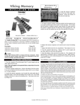
A. DVA-2W Memory Expansion
1. Disconnect the power to the DVA-2W.
2. Remove the (2) screws on the bottom of the unit,
then remove the cover.
3. Insert the ERAM chip(s) carefully into the appro-
priate socket(s) with the indents facing in the dir-
ection shown in the diagram below.
4. Replace the cover and screws of the DVA-2W.
Model
DVA-2W
DVA-500A
DVA-1003B
DVA-3003
FBI-1A
# of Kits
up to 3
1
up to 3
up to 9
1
Factory Record Time
1 minute
16 seconds
16 seconds per channel
1 minute per channel
(3 minutes total)
16 seconds
Maximum Record Time
4 minutes
1 minute
1 minute
4 minutes per channel
(12 minutes total)
1 minute
VIKING ELECTRONICS
ERAM-60 REV B
Kit 3
Kit 2
Kit 1
ERAM-60
record time. The num-
ber of chips required is
dependant on the
record time required
and the capacity of the
announcer.

Due to the dynamic nature of the product design, the information contained in this document is subject to change without notice. Viking Electronics, and its affiliates and/or
subsidiaries assume no responsibility for errors and omissions contained in this information. Revisions of this document or new editions of it may be issued to incorporate
such changes.
Fax Back Doc 813
ZF300160 Rev D
Printed in the U.S.A.
P
P
r
r
o
o
d
d
u
u
c
c
t
t
S
S
u
u
p
p
p
p
o
o
r
r
t
t
L
L
i
i
n
n
e
e
.
.
.
.
.
.
7
7
1
1
5
5
.
.
3
3
8
8
6
6
.
.
8
8
6
6
6
6
6
6
F
F
a
a
x
x
B
B
a
a
c
c
k
k
L
L
i
i
n
n
e
e
.
.
.
.
.
.
7
7
1
1
5
5
.
.
3
3
8
8
6
6
.
.
4
4
3
3
4
4
5
5
I
I
n
n
s
s
t
t
a
a
l
l
l
l
a
a
t
t
i
i
o
o
n
n
Important: Electronics componants are sensitive to stat-
ic electricity. Personnel and the work area should be
grounded before handling.
B. DVA-500A and DVA-1003B Memory Expansion
1. Disconnect the power and telecom connections to the
DVA-500A or DVA-1003B.
2. Remove the (4) screws on the bottom of the unit, then
remove the cover.
3. Insert the ERAM chip(s) carefully into the appropriate
socket(s) with the indents facing in the direction shown.
4. Replace the cover and screws of the DVA-500A or
DVA-1003B.
Important: Electronics componants are sensitive to static electricity. Personnel and the work area should be ground-
ed before handling.
C. DVA-3003 Memory Expansion
1. Disconnect the power and telecom connections to the DVA-3003.
2. Remove the (4) screws on the bottom of the unit, thenremove the cover.
3. Insert the ERAM chip(s) carefully into the appropriate socket(s) with the indents facing in the direction shown below.
4. Replace the cover and screws of the DVA-3003.
Important: Electronics componants are sensitive to stat-
ic electricity. Personnel and the work area should be
grounded before handling.
D. FBI-1A Memory Expansion
1. Disconnect the power and telecom connections to the
FBI-1A.
2. Remove the circuit board by spreading the aluminum
housing until the board is free.
3. Insert the ERAM chip(s) carefully into the appropriate
socket(s) with the indents facing in the direction shown.
4. Place the board back into the chassis of the FBI-1A.
258511 REV B
LED
LED
21
LED LED
3
LED LED LED
33
333
VIKING ELECTRONICS
ERAM-60 REV B
ERAM-60
VIKING ELECTRONICS
ERAM-60 REV B
ERAM-60
VIKING ELECTRONICS
ERAM-60 REV B
ERAM-60
Kit 1 Kit 2 Kit 3
Channel 1
Kit 1 Kit 2 Kit 3
Channel 2
Kit 1 Kit 2 Kit 3
Channel 3
-
 1
1
-
 2
2


Viking Electronics DVA-2W User manual
- Type
- User manual
- This manual is also suitable for
Ask a question and I''ll find the answer in the document
Finding information in a document is now easier with AI
Other documents
-
Kenwood AVS-1003B User manual
-
Viking K-1705-3 User manual
-
Viking RHI4011 User manual
-
-
 Viking InterWorks 650CT User manual
-
Meicheng MX-1003 Owner's manual
-
-
Viking 25AE Technical Practice
-
Viking the aes-2000 accessible entry system User manual
-
Viking ACD-10 User manual
