Castle Creations CSE010010400 User guide

Type
User guide

This manual is also suitable for

© 2013 Castle Creations, Inc. P/N: 095-0176-00 Revisi on Date - 03/2013 PAGE 1 of 6
Safety First!
For use by adults only.
An electric motor that is connected to a battery and speed control may start
unexpectedly and could cause serious injuries.
Always treat a powered system with respect.
Always remove the propeller or disengage the pinion gear when you are working on a
plane or helicopter with the battery connected.
Please observe all local laws regarding the flying of remote control aircraft or other
control of remote control vehicles
Never fly over others or near crowds.
Never fly a controller that has been involved in a serious crash. Send it back to Castle for
inspection as there may be damage that is not visible to the untrained eye.
Castle Creations is not responsible for your use of this product, or any damage or
injuries you may cause or sustain as a result of its usage.
INSTALLING YOUR EDGE ESC
1. Add your battery connector
You must attach a quality battery connector of your choice to the red (+) and black (-) power wires. Solder the battery
connector to the wires. ENSURE THAT THE POLARITY IS CORRECT (red wire to battery red wire, black wire to battery black
wire). Follow the instructions provided with the battery connector.
2. Connect the motor to your ESC
Solder the corresponding connectors for your motor to the wires coming from the ESC, or solder the motor wires directly to
the motor leads on the ESC.
Always use electronics grade solder and make sure your solder joint is solid. Poor soldering is a common cause of in-flight
failure! Ensure connectors are properly protected with insulation or heat-shrink to prevent shorts.
3. Connect the ESC to your receiver
Connect the receiver lead (the brown/red/orange wires with a black plastic connector on the end) to the throttle channel on
your receiver.
If you choose to use the white AUX Line, discussed later, please connect it as needed.
4. BEC operation.
The Edge and Edge LITE controllers have an onboard BEC circuit that provides power for the RX and servos. This BEC is
capable of supplying up to 5 amps of power. If the servos in the system draw more current, even briefly, please use an
outboard power source. Castle’s CC BEC PRO is highly recommended.
If an external power source is used, the red wire on the Edge throttle cable must be disconnected from the wiring harness.
We recommend lifting the plastic retaining tab and sliding the small connector out of the housing. Cover this connector with
tape or shrink wrap.
www.castlecreations.com/edge
© 2013 Castle Creations, Inc. P/N: 095-0176-00 Revisi on Date - 03/2013 PAGE 2 of 6
NOTE TO USERS WITH A FUTABA TRANSMITTER: You must reverse the throttle channel signal on your transmitter. Please
refer to your Futaba instructions.
5. Reversing rotation (if necessary)
You may wish to bench test the motor and speed control to determine the rotation of the motor. To change the rotation of
the motor, swap ANY two motor wire connections, or use the Castle Link USB interface to change the rotation direction.
6. Mounting the ESC
Edge ESCs have mounting tabs for your convenience. We recommend using Velcro or double sided tape to attach the Edge
LITE ESCs to the airframe.
Never place undue strain on the ESC by using zip ties on the wires within 1 inch of the controller.
Never use zip ties on the body of an Edge LITE controller.
7. Initialization sequence
1. Ensure that the Edge is connected to the throttle channel on your receiver.
2. Turn your transmitter ON and set the throttle stick to mid-throttle.
3. Connect the motor battery to the speed controller. The speed controller will remain disarmed and will not operate the
motor until it receives the 0% throttle signal.
When you are ready to fly, move the throttle stick to the lowest position on your transmitter.
The Edge will beep the motor to indicate that it is armed.
Always power your radio transmitter before powering up the receiver and/or the ESC. Some receivers failsafe features,
those that are not bound to a transmitter on receiver power up, or those that have a “power-up” output signal that is
dierent from fail safe settings or the stick positions on the TX may cause the arming sequence to occur and command the
ESC to drive the motor.
Using channels other than the radio TX manufacturer’s recommended throttle channel may lead to unwanted or dangerous
results. Use non-throttle channels to control the ESC at your own risk.
Always perform a range check at full, half, and zero throttle before flying any new speed controller! For helicopters, range
check with the blades o the helicopter at full, half, and zero throttle.
EDGE BEEP CODES/ LED PATTERNS
Edge ESCs are programmed to sound a number of tunes and codes using the motor as well as flashing LED patterns to alert
the user to certain conditions regarding the power system. The following chart describes these codes, “•” represents a short
beep and “
-
” represents a long beep.
TONE EDGE LED MEANING DESCRIPTION
“Castle Power” tune with
beeps corresponding to
number of cells
Blinks out cell count with
RED LED
Power up notice ESC plays Castle signature tone and beeps out the number of
cells attached to controller. Note: when Auto-LiPo detection is
disabled by the user, ESC will not beep the number of cells. ESC w
ill not run motor until it receives an arming signal from the radio
via the throttle lead.
Arming tune none ESC ready to run motor ESC plays the Castle arming tune once it receives a signal from
the receiver. Controller is ready to run the motor at this point.
RED LED matches tone Powered ESC notice ESC beeps motor every 10 seconds to remind user that power is
connected to the ESC. This notice may be disabled in Castle Link.
-
RED LED matches tones Low Voltage Cuto Main battery voltage dropped below the cuto value. The default
is Auto-LiPo which sets the cuto value based on the detected
cell count. Other settings may be entered in Castle Link.
-
RED LED matches tones Over Temperature ESC reached an overtemp condition. Occurs when operated under
too high a load or operated without proper cooling airflow.
© 2013 Castle Creations, Inc. P/N: 095-0176-00 Revisi on Date - 03/2013 PAGE 3 of 6
--
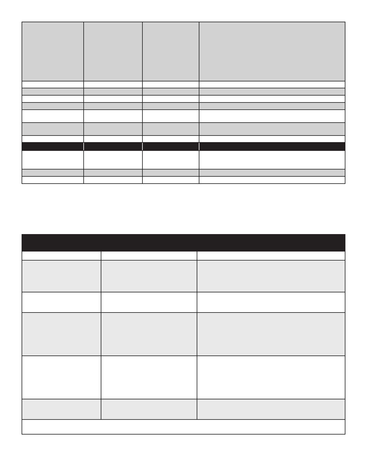
RED LED matches tones Excessive Load ESC detected very high current spikes. Causes may include
damaged wiring leading to, or inside, the motor, or the use of too
large a motor for the controller.
Remove power from the controller and check for shorts. If none
are found, verify the controller can handle the motor’s current
load. As a safety feature, if multiple Excessive Load errors are
detected, beeping will be disabled.
If error continues, contact Castle Tech Support.
•• RED LED matches tones Start Fail ESC was unable to start motor.
••
-
RED LED matches tones Radio Glitch ESC detected unusual signals or loss of signal on throttle wire.
••• RED LED matches tones Motor Anomaly ESC detected a sudden interruption of the motor’s rotation.
-
RED LED matches tones Over-Current ESC detected operating currents that exceed the cuto value.
-
•• RED LED
matches tones
AUX Wire Glitch ESC detected unusual signals or loss of signal on the AUX line.
None Flashing GREEN LED Locked head speed Governor mode has reached programmed head speed and is now
locked.
None SOLID RED LED Full throttle ESC is at full throttle.
TONE EDGE LED MEANING DESCRIPTION
None Alternating RED LED and
YELLOW LED
Arm Lock The ESC is currently in the Arm Lock state and will not allow
the controller to be armed. For more information the Arm Lock
feature and the AUX wire, see page ???.
None Blinking YELLOW LED Logging data The ESC is recording a datalog entry.
None SOLID YELLOW LED Data log full The ESC’s data log is now full.
EDGE CONTROLLER AUX LINE (WHITE WIRE) MODES
Edge controllers oer an AUX LINE, which is the extra white wire connected to the receiver cable. This line may be used for
a variety of tasks. The AUX line is disabled until another selection is made using the Castle Link USB adapter and the Castle
Link Program. Only one mode may be selected at a time.
SETTING AUX LINE CONNECTION
AND SPECS
BEHAVIOR
DISABLED NOT USED Disables output/input of the auxiliary wire. Factory Setting
GAIN INPUT
(ESC must be in a governor mode)
Connect the AUX line to an open channel
on your receiver.
Use to adjust the governor gain in real time.
0% TX signal equals a gain of 1 (min)
100% TX signal equals a gain of 50 (max)
AUDIBLE BEACON Connect AUX line to an open channel on
your receiver.
The controller will use the motor to emit an audible locator signal
when the AUX LINE is above 50%. The beacon is only emitted if
the motor is not running.
RPM OUT Connect the AUX line to 3 axis gyros that
supports RPM sensors.
The ESC toggles the AUX LINE at every electrical commutation.
Divide this number by your number of magnetic pole pairs for
mechanical RPM.
ARM LOCK KEY* Requires the Arm Lock Key Harness,
(Coupon in package may be redeemed for
an Arm Lock Key) which attaches to the
AUX LINE and the receiver.
While the key is in the socket, the controller will be incapable of
arming. Once removed, the ESC will arm when it receives the low
throttle command on the traditional throttle line.
If the key is inserted while the motor is running, the ESC will go
into the ARM LOCKOUT state stopping the motor from running and
preventing the ESC from arming.
RX ARM LOCK* Connect the AUX line to an open channel
on your receiver that is programmed to
serve as an arm lock switch.
The controller won’t arm or run when the auxiliary channel is
below 50%.
*The ARM LOCK KEY and RX ARM LOCK features should be used as an extra safety measure NOT to replace general safety precautions. NEVER
leave vehicle unattended or rely solely on the ARM LOCK feature to guarantee safety.
SUMMARY OF FEATURES ACCESSIBLE IN CASTLE LINK
Procedure for connecting Edge Series to Castle Link
© 2013 Castle Creations, Inc. P/N: 095-0176-00 Revisi on Date - 03/2013 PAGE 4 of 6
Castle Link operation.
1. Connect Castle Link USB device to Windows PC running Castle Link Application. Ensure USB link is detected. Green
“Light” on interface screen will confirm USB connection.
2. Plug the controller into the Castle Link using the ESC throttle connector.
DATA LOGGING
Use Castle Link software to modify data logging settings. The capabilities are briefly described below. See the help files and
on screen instructions in Castle Link and Castle Link Graph Viewer for complete details.
*Duration of recording
The ESC writes the recorded data to a limited amount of memory. Recording time varies with the data points selected and the sample rate. the ESC compresses data wherever possible;
periods at IDLE or constant throttle do not take very much memory. Use the Castle Link software to select or remove values from the data logged by the ESC.
Automatic Data Reset
At power up, Automatic Data Reset checks the amount of memory used. If that value is more than the programmed limit, the
controller will erase the entire data log. This ensures that the last few runs are saved to memory and available for analysis.
Manual Data Reset
Power controller up with TX & RX on and set to full throttle. The controller will chime the normal power up chimes. Leave
TX at full throttle for 6 seconds after power up. The controller will emit a short tone after 1 second and then a long tone
5 seconds later. The controller will then erase the entire data log. Move the throttle stick to lowest position to arm the
controller.
DATA ANALYSIS
Use Castle Link USB adapter and the Castle Link Windows software to read, analyze and store the data recorded on the ESC.
Phoenix Edge controllers support Castle Link Live for real telemetry feedback. For more information,
visit castlecreations.com/CastleLinkLive.
PROGRAMMABLE SETTINGS WITHOUT A COMPUTER - STICK PROGRAMMING
The Edge firmware is designed to make it dicult to accidentally enter programming mode. Stick programming can only
oer access to a small subset of the settings available on the controller. Castle highly recommends using the Castle Link USB
device and our free Windows application to make settings changes on your ESC if at all possible.
Overview
Once in programming mode, the Edge ESC “asks” questions by beeping and flashing the setting number, followed by the
number for each of the setting values. You must answer “yes” or “no” by moving the throttle stick on your transmitter as the
Edge ESC presents them. The values are always presented in sequence, and do NOT “tell you” what any of the settings are
currently programmed for.
The current setting and setting value are “flashed” out by the LED. (For example if you are on setting #3 and value #2, there
will be 3 beeps/flashes, then 2 beeps/flashes repeating until you answer). Answering “no” to a setting value will cause the
Edge ESC to ask for the next value in sequence. Answering “yes” to a setting value will store that setting in the permanent
memory, and skip to the next setting.
© 2013 Castle Creations, Inc. P/N: 095-0176-00 Revisi on Date - 03/2013 PAGE 5 of 6
NOTE: If you answer “no” to all values for a particular setting, the ESC will keep whatever value had been previously
programmed. Only by answering “yes” to a value will the Edge ESC store/change any value.
You will need to move the transmitter stick to the “yes” (full throttle) position or the “no” (zero throttle) position to answer
the question. When the Edge ESC has accepted your answer, it will flash the LED rapidly, and emit a constant beeping. Move
the throttle stick back to the middle position for the next question.
If you wish to re-program only some of the features you do not need to continue through the programming steps for the
remaining settings. Once you have programmed each of the features you wish to change and the Edge ESC has confirmed
the selection, instead of returning to mid-throttle for the next question, disconnect battery power, re-connect power, and
arm the speed control as normal.
Before manual programming, remove the prop or pinion to ensure safety.
Enter Programming Mode
1. The Edge controller must be connected to a motor to sound beeps. Turn your transmitter on, and leave the Edge ESC
unpowered. Move the transmitter stick to the top position (full throttle).
2. Connect battery power to the Edge ESC. The Edge ESC will beep its initialization tones when first plugged in. After a
short period of time the Edge ESC will emit another short tone and the LED on the Edge ESC should flash a short, single
flash that repeats. If the ESC flashes continuously it is not seeing a full throttle position. Move your throttle trim to the top
position or increase your full throttle endpoint or ATV on your transmitter.
3. Move your transmitter stick to the middle position. The Edge ESC will emit another short tone, and the LED on the Edge
ESC should flash a short, double flash that repeats.
4. Move your transmitter stick back to the top position again. After a short time, the Edge ESC will emit a short tone, and
the LED on the Edge ESC should flash a short, triple flash that repeats.
5. Move your transmitter stick back to the middle position again. The Edge ESC will emit four short tones in a row, and the
LED on the Edge ESC will start a repetitive flash sequence of a single flash followed by a long pause.
The Edge ESC is now in programming mode and asking you the first question.
Stick programming oers quick access to basic settings only.
Many more may be accessed using Castle Link and a Windows PC.
SETTINGS 1: LOW VOLTAGE CUTOFF BATTERY CELL CUTOFF VOLTAGE*
Option 1: 3.0V per cell
Option 2: 3.1V per cell
Option 3: 3.2V per cell (Factory Setting)
Option 4: 3.3V per cell
Option 5: 3.4V per cell
Option 6: DISABLED
SETTINGS 2: BRAKE TYPE
Option 1: Soft Delayed Brake
Option 2: Hard Delayed Brake
Option 3: Soft Brake - No Delay
Option 4: Hard Brake - No Delay
Option 5: Brake Disabled (Factory Setting)
SETTING 3: LOW VOLTAGE CUTOFF TYPE
Option 1: Hard Cuto
Option 2: Soft Cuto (Factory Setting)
Option 3: RPM Decrease
Option 4: Pulsing RPM (ESC pules throttle)
SETTINGS 4: PWM SWITCHING RATE**
Option 1: 8kHz (Outrunners)
Option 2: 12 kHz (Factory Setting)
Option 3: 16 kHz
* Refer to cell vendor’s instructions for cuto voltage
** Refer to motor manufacturer’s instructions for frequency settings.
© 2013 Castle Creations, Inc. P/N: 095-0176-00 Revisi on Date - 03/2013 PAGE 6 of 6
NON-WARRANTY REPAIRS
Never throw away a damaged Edge! You may send it to Castle and take advantage of our flat price replacement oer. Please
check our website for specific pricing.
CONTACT & WARRANTY INFO
Your Edge ESC is warranted for one year from date of purchase to be free from manufacturing and component defects*.
This warranty does not cover abuse, neglect, or damage including, but not limited to, incorrect wiring, over voltage, or
overloading.
To return your controller for warranty or repair, please go to www.castlecreations.com and complete the data entry page.
Print the resulting form and include it in the package with your controller. Send the package to the address below - or to one
of the addresses listed on the web site that may be more suited for your location.
*Your warranty may vary based on the laws of the country where the product was purchased.
If you have any questions, comments, or wish to return your Edge ESC for warranty or non-warranty repair or replacement,
contact Castle Creations, Inc. at:
540 North Rogers Road
Olathe, Kansas 66062 USA
www.castlecreations.com
Phone: (913) 390-6939
Fax: (913) 390-6164
LEGAL
Designed in Kansas
Components manufactured in the USA, Mexico, and China using parts sourced globally.
All Castle Edge ESCs are certified by Castle Creations, Inc. to be CE compliant.
All Castle Edge ESCs are manufactured in accordance with RoHS standards.
Specifications, including performance, dimensions, and functions are subject to change at any time and without notice. ALWAYS REFER TO THE QUICK START GUIDE FOR THE SPECIFIC CONTROLLER
OR TO THE CASTLE LINK SOFTWARE FOR DETAILS ON THE OPERATIONAL ASPECTS OF THE HARDWARE/SOFTWARE SYSTEM.
Castle Creations logos and Edge logos are trademarks of Castle Creations, Inc.
This manual is copyright © Castle Creations, Inc. 2013.
U.S. patents #7,492,122 and 7,400,103 apply. Other patents pending.
EUROPEAN UNION COMPLIANCE INFORMATION
(in accordance with ISO/IEC 17050-1)
Castle CE Declaration: CE DEC 2013-01, CE DEC 2013-02
Product(s): Phoenix Edge 50, Phoenix Edge 75, Phoenix Edge 100, Phoenix Edge 130, Phoenix Edge 200, Phoenix Edge Lite 50, Phoenix Edge Lite 75, Phoenix Edge Lite 100, Phoenix Edge Lite 130,
Phoenix Edge Lite 200
Item Number(s): 010-0102-00, 010-0101-00, 010-0100-00, 010-0099-00, 010-0098-00, 010-0113-00, 010-0112-00, 010-0111-00, 010-0110-00, 010-0109-00
The objects of the declaration described above are in conformity with the requirements of the specifications listed below, following the provisions of the European EMC Directive 2004/108/EC:
EN61000-6-1:2007
EN61000-6-3:2007
Signed for and on behalf of:
CASTLE CREATIONS, INC.
540 N. Rogers Rd.
Olathe, KS 66062 USA
January 25, 2013
L. E. Estingoy III
Corporate Counsel
Castle Creations, Inc.
Instructions for disposal of WEEE by users in the European Union
This product must not be disposed of with other waste. Instead, it is the user’s responsibility to dispose of their waste equipment by handing it over to a designated collections point for the
recycling of waste electrical and electronic equipment. The separate collection and recycling of your waste equipment at the time of disposal will help to conserve natural resources and
ensure that it is recycled in a manner that protects human health and the environment.
  • Page 1 1
  • Page 2 2
  • Page 3 3
  • Page 4 4
  • Page 5 5
  • Page 6 6

Castle Creations CSE010010400 User guide

Type
User guide
This manual is also suitable for

Ask a question and I''ll find the answer in the document

Finding information in a document is now easier with AI