Page is loading ...

English
12.0785.2101E
www.rotronic.com
HYGROFLEX73A-SERIES
Short Instruction Manual
1 GENERAL DESCRIPTION
The HygroFlex73A-Series devices are universal transmitters for transmission of humidity and tem-
perature measurements. These short instructions are limited to a description of the main functions
and installation of the device. The detailed instruction manual can be found on the internet at:
www.rotronic.com
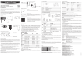
2 DIMENSIONS / CONNECTIONS
Duct-Version (Standard)
(Type-Q) for ø 25/15 mm probe
Drill template for all types Service interface
3 MECHANICAL INSTALLATION
3.1 GENERAL RECOMMENDATIONS
Relative humidity is extremely temperature-dependent. In order to measure it exactly, the probe
and sensors must be set exactly on the temperature level of the environment that is to be mea-
sured. The installation site can therefore have a signicant inuence on the performance of the
device. Follow the guidelines below to ensure optimum performance:
a. Select a representative installation site: Install the probe at a point where the humidity,
temperature and pressure conditions are representative for the environment that is to be
measured.
b. Make sure there is sufcient air movement around the probe: An air ow of at least 1 metre/
second accelerates and facilitates adjustment of the probe to changing temperatures.
c. Avoid:
1. Probe too close to heating elements, cooling coils, cold or hot walls, direct sunlight, etc.
2. Probe too close to steam, injectors, humidiers or direct precipitation.
3. Unstable pressure conditions with high air turbulence.
d. Insert the probe as far as possible into the environment that is to be measured.
e. Avoid accumulation of condensation at the contact wires of the sensor. Install the probe so
that the tip points down. If that is not possible, install it in horizontal position.
3.2 MOUNTING THE VERSION TYPE-Q
To avoid measurement errors, at least 200 mm of the probe should be inserted into the environ-
ment that is to be measured. If necessary, use the mounting ange AC1303-M and AC1304-M (only
for type-Q) to install the probe and fasten the transmitter.
4 ELECTRICAL INSTALLATION
4.1 GENERAL WIRING GUIDELINES
Heavy machinery and instrumentation should not share the same power supply wiring. If this can-
not be avoided, noise lters and surge protectors should be used. Most UPS devices have those
features already integrated.
4.2 LIGHTNING PROTECTION
Cabling in areas with a risk of lightning requires a lightning protection. For cabling underground in
between buildings, we recommend the use of special ber optic cables. If this is not possible, use
copper cables that are suitable for underground installation.
4.3 CABLE GRIP AND CABLE SPECIFICATIONS
The HF7 is supplied either with one M16 sealing cable gland. The M16 cable gland provides effec-
tive sealing only with cables having the proper outside diameter. Preferably, use a cable with an
outside diameter of 6 to 7 mm (0.236 to 0.275 inch) with 18 AWG wires.
4.4 GROUNDING
Generally it is recommend grounding the (-) side of the power supply, especially if the electronics
are exposed to an environment with low humidity (35 %rh or less).
4.5 POWER SUPPLY
HF73: (3-wire with analogue outputs): 15 to 40 VDC or 12 to 28 VAC. When both outputs are con-
nect-ed, the maximum current consumption is 50 mA.
4.6 SUPPLY VOLTAGE / TECHNOLOGY
Type Supply voltage V+ Load Output
3-wire
HF732 15...40 VDC / 12...28 VAC Max 500 Ω 4...20 mA
Caution: Wrong supply voltages and excessively high loading of the outputs can damage
the transmitter.
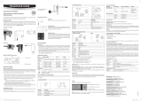
4.7 TERMINAL CONFIGURATION / CONNECTION DIAGRAMS
The type is dened using the table Supply voltage / Technology to then use the following connec-
tion diagrams:
3-wire circuit / HF73A
Terminal Tuchel connector Description
K1-1 OUT1 6 Analogue humidity-/dew point output +
K1-2 OUT2 4 Analogue temperature output +
K1-3 GND 3 and 5 Analogue GND
K1-4 GND 3 and 5 Analogue GND
K2-1 PWR 1 Supply voltage + / Phase
K2-2 GND 2 GND / Neutral
5 PROGRAMMING
The basic settings of the devices are made in the factory according to your order. The transmitters
are adjusted in the factory and therefore do not need to be checked and readjusted during installa-
tion. The devices can be started immediately after installation.
6 SOURCES OF ERROR
Measured values can be inuenced by the following factors:
Temperature errors
Adaptation time too short, cold outside wall, heating elements, sunlight, etc.
Humidity errors
Steam, water spray, dripping water or condensation at the sensor, etc. Repeatability and long term
stability are, however, not inuenced by these factors even if the probe is exposed to high humidity
or saturation with steam (condensation) over a longer period of time.
Soiling
By dust in the air. The choice of probe lter depends on the amount of soiling at the measuring
point. The lter must be cleaned or replaced periodically.
7 SCALING / ADJUSTMENT / FIRMWARE UPDATE
The following settings can be made with the help of the HW4 software and either the service cable
AC3006 or AC3009:
• New scaling of the outputs
• Adjustment
• Firmware update
A detailed description can be found in the manual, which can be downloaded from our website
www.rotronic.com.
8 PERIODIC CALIBRATION OF THE PROBE / TRANSMITTER
Both the PT100 RTD temperature sensor and the corresponding electronics are very stable and
do not normally need to be changed or calibrated after factory calibration. The long term stability
of the Rotronic Hygromer humidity sensors is typically better than 1 %rh per year. For maximum
accuracy we recommend calibration of the probe about every six to 12 months. More frequent cali-
bration can be necessary in applications where the sensor is exposed to pollutants. The calibration
can be performed by the user himself on site or in the laboratory / workshop. For routine calibra-
tions the probe should be checked at one or two points. The electronics of the transmitter do not
normally require calibration in the eld.
They can be checked easily with the help of the probe simulator in the HW4 software package. The
electronics can not be repaired in the eld and should be returned to the manufacturer in the case
of problems. For details on calibration, please see the full version of the instruction manual, which
you can download from the internet.
Cleaning or replacing the dust lter (optional)
Depending on the conditions of measurement, the lter should be checked from time to time.
Cor-roded, discolored or clogged lters should be replaced. The probe of the HF7 has a removable
lter.
9 TECHNICAL DATA
Measurement
Temperature / Humidity
Type Q with PPS Probe -100…200 °C / 0…100 %rh
Accuracy ±1.0 %rh, ± 0.2 K @ 23 °C
Protection IP65 unamable
Output Current or voltage signals
Operation
Temperature -40...85 °C
Humidity 0...100 %rh, non-condensing
OK
OK
AC1304-M and
AC1306 Mounting
ange for 25 mm probe
AC1303-M and
AC1305 Mounting
ange for 15 mm probe
AC1303/4-M
Current output
Voltage output
=
~
K2: PWR
K2: GND
K1: GND
K1: OUT1
K1: OUT2
K2: PWR
K2: GND
K1: GND
K1: OUT1
K1: OUT2
PWR
GND
2
1
GND
1
2
3
OUT1
OUT2
4
GND
280
Service interface
(Mini-USB)
Ø 8.5 mm Upper
surface
Mounting
surface
Ø 4.5 mm
1 mm
11 mm
41 mm
/