Fanimation Studio Collection LP7678LBN Installation guide
- Category
- Household fans
- Type
- Installation guide

Net Weight 16.47 lbs (7.47 kgs)
Questions, problems, missing parts? Before returning to your retailer, call our customer
service department at 1-888-567-2055, 8 a.m.-5 p.m., EST, Monday-Friday.
Date Code
For best and quickest service please provide date code. You can find the date code on the carton or
top of fan housing.
Purchase Date
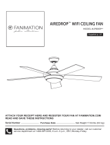
ATTACH YOUR RECEIPT HERE AND REGISTER YOUR FAN AT FANIMATION.COM
READ AND SAVE THESE INSTRUCTIONS
Español p. 21
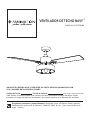
MODEL #LP7678LBN
NAVY CEILING FAN
™

Important Safety Instructions
WARNING: To avoid fire, shock and serious personal injury, follow these instructions.
Additional Safety Instructions
2. Before servicing or cleaning unit, switch power off at service panel and lock service panel disconnecting means to prevent power
1. Read your owner’s manual and safety information before installing your new fan. Review the accompanying assembly diagrams.
from being switched on accidentally. When the service disconnecting means cannot be locked, securely fasten a warning device, such
as a tag, to the service panel.
3. Be careful of the fan and blades when cleaning, painting, or working near the fan. Always turn off the power to the ceiling fan before
servicing.
4. Do not insert anything into the fan blades while the fan is operating.
5. The appliance is not intended for use by young children or infirm persons without supervision. Young children should be supervised to
ensure that they do not play with the appliance.
1. To avoid possible shock, be sure electricity is turned off at the fuse box before wiring, and do not operate fan without blades.
2. All wiring and installation procedures must satisfy National Electrical Codes (ANSI/ NFPA 70) and Local Codes. The ceiling fan
must be grounded as a precaution against possible electrical shock. Electrical installation should be made or approved by a licensed
electrician.
3.
4. The fan must be mounted with the fan blades at least 7 feet from the floor to prevent accidental contact with the fan blades.
The fan base must be securely mounted and capable of reliably supporting at least 35 lbs. See page 5 of owner’s manual for
Follow the recommended instructions for the proper method of wiring your ceiling fan. If you do not have adequate electrical
5.
knowledge or experience, have your fan installed by licensed electrician.
support requirements. Consult a qualified electrician if in doubt.
6. This fan is to be used in dry locations.
7. For supply connections, if the conductor of a fan is identified as a grounded conductor, then it should be connected to a grounded
conductor power supply. If the conductor of a fan is identified as an ungrounded conductor, then it should be connected to an
ungrounded conductor power supply. If the conductor of a fan is identified for equipment grounding, then it should be connected to an
equipment grounding conductor.
- Reorient or relocate the receiving antenna.
- Increase the separation between the equipment and the receiver.
- Connect the equipment into an outlet on a circuit different from that to which the receiver is connected.
Consult the dealer or an experienced radio/TV technician for help.
ceiling fan’s remote control unit.
operate the equipment.
CAUTION: Changes or modifications not expressly approved by the party responsible for compliance could void the user’s authority to
WARNING: This product is designed to use only those parts supplied with this product and/or accessories designated specifically for
use with this product. Using parts and/or accessories not designated for use with this product could result in personal injury or property
damage.
WARNING: To reduce the risk of personal injury, do not bend the blade bracket (flange or blade holder) when installing the brackets,
WARNING: Mount to an outlet box marked acceptable for fan support of 15.9 kg (35 lbs) or Less.
balancing the blades, or cleaning the fan. Do not insert foreign objects in between rotating fan blades.
WARNING: Do not operate this fan with a variable (Rheostat) wall controller or dimmer switch. Doing so could result in damage to the
WARNING: While Optional Remote Controls Are Available for This Ceiling Fan, To Reduce The Risk Of Fire, Electric Shock, And Injury
To Persons, This Ceiling Fan Must Only Be Installed With CR500 Remote Control Accessory, That Are Marked on their Cartons To Indicate
The Suitability With This Model. Other Remote Control Cannot Be Substituted.
This device complies with Part 15 of the FCC Rules. Operation is subject to the following two conditions:
(1) This device may not cause harmful interference, and (2) this device must accept any interference received, including
interference that may cause undesired operation. Please note that changes or modifications not expressly approved by the
party responsible for compliance could void the user's authority to operate the equipment.
Note: This equipment has been tested and found to comply with the limits for Class B digital device, pursuant to part 15 of
the FCC Rules. These limits are designed to provide reasonable protection against harmful interference in a residential
installation.
This equipment generates, uses and can radiate radio frequency energy and, if not installed and used in accordance with the
instructions, may cause harmful interference to radio or television reception, which can be determined by turning the
equipment off and on, the user is encouraged to try to correct the interference by one or more of the following measures:
8. This fan is suitable for use with optional solid-state speed control CR500.
WARNING: TO REDUCE THE RISK OF ELECTRIC SHOCK, THIS FAN MUST BE INSTALLED WITH A GENERAL USE ISOLATING
WALL CONTROL/SWITCH.

Table of Contents
1. LIMITED LIFETIME MOTOR WARRANTY - If any part of your fan motor fails, due to a defect in materials or workmanship during the
lifetime of the original purchaser, Fanimation will provide the replacement part free of charge, when the defective fan is returned
ro lavomer eht ni derrucni stsoc lla rof elbisnopser eb llahs remotsuC .deriuqer si esahcrup fo foorP .retnec ecivres lanoitan ruo ot
reinstallation and shipping of the product for repairs or replacement.
ot eud ,esahcrup lanigiro eht morf raey eno nihtiw emit yna ta sliaf rotom naf ruoy fI - YTNARRAW ROBAL ROTOM RAEY ENO.2
defects in materials or workmanship, labor to repair the motor will be provided free of charge at our national service center. lliw resahcruP
ro lavomer eht ni derrucni stsoc lla rof elbisnopser eb llahs remotsuC .doirep raey-eno siht retfa segrahc robal
rof elbisnopser eb
reinstallation and shipping of the product for repairs or replacement.
ew ,pihsnamkrow ro slairetam ni tcefed a ot eud ,esahcrup lanigiro retfa raey n oneihtiw emit yna ta sliaf naf ruoy fo trap rehto yna fI .3
will repair, or replace, at our option, the defective part free of charge for parts and labor performed at our national service center.
,gnidorroc ,gnittip ,gnitsur gnidulcni ,hsinif eht ni segnahc revoc ton seod ytnarraw siht ,snoitidnoc etamilc gniyrav fo esuaceB .4
tarnishing, or peeling.
fo semertxe ot erusopxe ,esusim ,tnedicca ,tcelgen ,noitallatsni reporpmi morf egamad ot ylppa ton seod dna diov si ytnarraw sihT .5
heat or humidity, or as a result of any modification to the original product.
ro naf eht dlos taht erots eht ton dna naf eht fo renwo eht fo ytilibisnopser elos eht era naf eht fo noitallatsnier dna lavomer fo stsoc llA .6
Fanimation.
7. Fanimation reserves the right to modify or discontinue any product at any time and may substitute any part under this warranty.
8. Under no circumstances may a fan be returned without prior authorization from Fanimation. The receipt of purchase must ac-
company authorized returns and must be sent freight prepaid to Fanimation. diova ot dekcap ylreporp eb tsum denruter eb ot naf ehT
damage in transit; Fanimation will not be responsible for any damage resulting from improper packaging.
ro desserpxe rehto on si erehT .noitaminaF morf elbaliava ydemer evisulcxe eht si tnemecalper ro riaper yna taht dootsrednu si tI.9
dna ytilibatnahcrem fo esoht ot detimil ton tub ,gnidulcni ,seitnarraw deilpmi lla dna yna smialcsid ybereh noitaminaF .ytnarraw deilpmi
fitness for a particular purpose to the extent permitted by law. Some states do not allow limitations on implied warranties. lliw noitaminaF
not be liable for incidental, consequential, or special damages arising out of or in conjunction with product use or performanc sa tpecxe ,e
ot etats morf yrav taht sthgir rehto evah osla yam uoy dna sthgir lagel laiceps uoy sevig ytnarraw sihT .wal yb dedrocca eb esiwrehto yam
state.
10. A certain amount of wobble is normal and should not be considered a problem or a defect.
4
5
5
7
9
10
11
11
12
14
15
15
16
17
18
LIMITED LIFETIME WARRANTY
Extends to the original purchaser of a Fanimation fan from an authorized Fanimation dealer/retailer only
Unpacking Instructions . . . . . . . . . . . . . . . . . . . . . . . . . . . . . . . . . . .
Energy Efficient Use of Ceiling Fans . . . . . . . . . . . . . . . . . . . . . . . .
Electrical and Structural Requirements . . . . . . . . . . . . . . . . . . . . . .
How to Assemble Your Ceiling Fan. . . . . . . . . . . . . . . . . . . . . . . . . .
How to Hang Your Ceiling Fan . . . . . . . . . . . . . . . . . . . . . . . . . . . . .
How to Wire Your Ceiling Fan . . . . . . . . . . . . . . . . . . . . . . . . . . . . .
How to Install Your Canopy Housing . . . . . . . . . . . . . . . . . . . . . . .
How to Assemble Your Ceiling Fan Blades . . . . . . . . . . . . . . . . . .
How to Assemble Your Light Kit . . . . . . . . . . . . . . . . . . . . . . . . . . .
How to Operate Your Ceiling Fan . . . . . . . . . . . . . . . . . . . . . . . . . .
Maintenance . . . . . . . . . . . . . . . . . . . . . . . . . . . . . . . . . . . . . . . . . . .
How to Clean Your Ceiling Fan Blades . . . . . . . . . . . . . . . . . . . . . .
Troubleshooting . . . . . . . . . . . . . . . . . . . . . . . . . . . . . . . . . . . . . . . .
Parts List . . . . . . . . . . . . . . . . . . . . . . . . . . . . . . . . . . . . . . . . . . . . . .
Exploded-View illustration . . . . . . . . . . . . . . . . . . . . . . . . . . . . . . . .

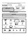
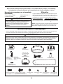
NOTE: Place the parts from the loose parts bags in a small
container to keep them from being lost. If any parts are
missing, contact your local retailer.
Materials
W
ARNING
Before assembling your ceiling fan, refer to section on
proper method of wiring your fan (page 10). If you feel you
do not have enough wiring knowledge or experience, have
your fan installed by a licensed electrician.
This manual is designed to make it as easy as possible for you to assemble,
install, operate and maintain your ceiling fan
Wiring outlet box and box connectors must be of type
required by local code. The minimum wire would be a 3-
conductor (2-wire with ground) of the following size:
nstalled ire ength
ire i e
p to ft
ft
Unpacking Instructions
For your convenience, check-off each step. As each step is completed, place a check mark. This will ensure that all steps have been
completed and will be helpful in finding your place should you be interrupted.
4
Tools Needed for Assembly
(Not Included)
• One Phillips head screwdriver
• One ¼˝ blade screwdriver
• One stepladder
• One wire stripper
1. Check to see that you have received the following parts:
NOTE: If you are uncertain of part description, refer to exploded view illustration.
WARNING
Do not install or use fan if any part is damaged or missing. This product is designed to use only those parts supplied with
this product and/or any accessories designated specifically for use with this product by Fanimation. Substitution of parts
or accessories not designated for use with this product by Fanimation could result in personal injury or property damage.
Contact your retail store for missing or damaged parts.
Hanger Bracket
Assembly (1)
Motor Coupling
Cover Assembly (1)
Hardware Bags
Motor Assembly (1) Blade Set (1)
Blade Holder Set (1)
Ceiling Canopy (1)
Light Shade Assembly (1)
Switch Housing Assembly (1)
Downrod/Hanger Ball Assembly (1)
– Downrod (1)
– Hanger Ball (1)
– Set Screw (1)
– Hairpin Clip (1)
– Clevis Pin (1)
– Pin (1)
Canopy Screw
Cover Assembly (1)
Fiber Washers
(10)
Wire Connectors (4) Fan Pull Chain (1) Light Kit Pull Chain
(1)
LED Bulb (1)
1/4″-20 Pan Head Screws
with Lock Washers (7)
3/16″-24 Truss Head
Screw With Spring Washer
/Flat Washer (10)

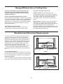
Electrical and Structural Requirements
Energy Efficient Use of Ceiling Fans
Ceiling fan performance and energy savings rely
heavily on the proper installation and use of the
ceiling fan. Here are a few tips to ensure efficient
product performance.
Using the Ceiling Fan Year Round
Summer Season: Use the ceiling fan in the
counterclockwise direction. The airflow produced by
the ceiling fan creates a wind-chill effect, making you
“feel” cooler. Select a fan speed that provides a
comfortable breeze, lower speeds consume less
energy.
Winter Season: Reverse the motor and operate the
ceiling fan at low speed in the clockwise direction.
This produces a gentle updraft, which forces warm air
near the ceiling down into the occupied space.
Remember to adjust your thermostat when using your
ceiling fan-additional energy and dollar savings could
be realized with this simple step!
Choosing the Appropriate Mounting Location
Ceiling fans should be installed, or mounted, in the middle
of the room and at least 7 feet from floor to the blade and
18 inches from wall to the blade. If ceiling height allows,
install the fan 8 - 9 feet from floor to the blade for optimal
airflow. Consult your Fanimation Retailer for optional
mounting accessories.
Turn Off When Not in the Room
Ceiling fans cool people, not rooms. If the room is
unoccupied, turn off the ceiling fan to save energy.
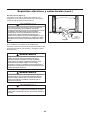
Your new ceiling fan will require a grounded electrical
supply line of 120 volts AC, 60 HZ, 15 Amp Circuit.
Electrical code requires use of a fan-rated outlet box to
support the extra weight and motion associated with a
ceiling fan. A fan-rated box will be labeled as such and
typically supports up to a 70lb ceiling fan. Fan-Rated
Outlet Boxes vary in ratings and design. Ensure the
ratings of your ceiling fan outlet box meet the
requirements for the ceiling fan being installed. Figure
1, Figure 2 and Figure 3 depicts different structural
configurations that may be used for mounting the outlet
box.
Low profile box (Figure 1)
A 1/2-in.-deep pancake box is meant to be screwed to a
joist or block. It’s used if only one cable is coming into the
box. It is also available in a saddle-mount configuration.
Deep box (Figure 2)
A 2-1/4-in.-deep box can be attached to blocking between
joists and is roomy enough to handle more than one cable.
CEILING JOIST
CEILING
OUTLET BOX
Figure 1
Figure 2
CEILING JOIST
2" x 4"
2" x 4"
CEILING
OUTLET BOX
5

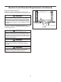
Electrical and Structural Requirements (Continued)
If your fan is to replace an existing light fixture, turn
electricity off at the main fuse box at this time and remove
the existing light fixture.
Turning off wall switch is not sufficient. To avoid
possible electrical shock, be sure electricity is turned off
at the main fuse box before wiring. All wiring must be in
accordance with National and Local codes and the ceiling
fan must be properly grounded as a precaution against
possible electrical shock.
WARNING
WARNING
WARNING
WARNING
Deep box with brace (Figure 3)
Paired with a deep box, this hanger is meant to span
between two joists and takes the place of wooden blocking.
To avoid fire or shock, follow all wiring instructions
carefully. Any electrical work not described in these
instructions should be done or approved by a licensed
electrician.
Figure 3
CEILING JOIST
CEILING
OUTLET BOX
To reduce the risk of fire, electric shock, or personal injury,
mount to outlet box marked acceptable for fan support of
15.9 kg (35 lbs) or less and use mounting screws provided
with the outlet box. Most outlet boxes commonly used for
the support of luminaires are not acceptable for fan support
and may need to be replaced, consult a qualified electrician
if in doubt.
Do not operate this fan with a variable (Rheostat) wall
controller or dimmer switch. Doing so could result in
damage to the ceiling fan’s remote control unit.
6

7
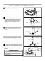
How to Assemble Your Ceiling Fan
2. Remove the hanger ball portion from the downrod/
hanger ball assembly by loosening the set screw in
the hanger ball until the ball falls freely down the
downrod. Remove the pin from the downrod, then
remove the hanger ball. Retain the pin and hanger
ball for reinstallation in Step 7. (Figure 2)
3. Remove the hairpin clip and clevis pin from the
bottom of the downrod. Retain the pin and clip for
reinstallation in Step 5. (Figure 3)
Figure 2
Figure 3
Figure 4
4. Loosen the two set screws and locking nuts in
the downrod support of the motor assembly. Route
the black, white and blue wires through the downrod.
(Figure 4)
Downrod
Set Screws (2)
Black, White
and Blue wires
Motor Stop
1. Remove and discard the six rubber motor stops
from the motor assembly by removing the screws.
(Figure 1)
Figure 1
Motor Assembly
Pin
Downrod
Hanger Ball
Set Screw

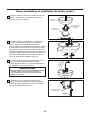
How to Assemble Your Ceiling Fan (Continued)
8
WARNING
It is critical that the clevis pin in the downrod support
is properly installed and the set screws and nuts are
securely tightened. Failure to do so could result in the
fan falling.
5. Thread downrod into the downrod support on top of
the motor. Install the clevis pin by aligning the holes
in the downrod support with holes in the downrod.
Secure clevis pin with hairpin clip. Tighten the two set
screws with nuts in the downrod support. (Figure 5)
Figure 5
Downrod
Set Screws and
Locking Nuts (2)
Hairpin Clip
Clevis Pin
6. Route wires through motor coupling cover, canopy
screw cover and ceiling canopy. (Figure 6)
Ceiling Canopy
Canopy Screw
Cover
Motor Coupling
Cover
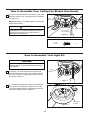
8. Cut off excess lead wire approximately 6 to 9 inches
above top of the downrod. Strip insulation off 1/2 inch
from the end of each lead wire. (Figure 8)
9.
Remove one of the two shoulder screws in the
hanger bracket and retain the screw for later. Loosen
the second shoulder screw without fully removing it.
(Figure 9)
Figure 9
Hanger Bracket
7. Reinstall the hanger ball on the downrod as follows.
Route the
black, white and blue wires through the
hanger ball. Position the pin through the two holes in
the downrod and align the hanger ball so the pin is
captured in the groove in the top of the hanger ball. Pull
the hanger ball up tight against the pin. Securely tighten
the set screw in the hanger ball. A loose set screw
could create fan wobble. (Figure 7)
Figure 8
CAUTION
All set screws must be checked, and retightened where
necessary before installation.
Figure 6
Figure 7

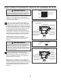
How to Hang Your Ceiling Fan
NOTE: If you are not sure if the outlet box is grounded,
contact a licensed electrician for advice, as it must be
grounded for safe operation.
1. Securely attach the hanger bracket to the outlet
box (not included) using the outlet box screws and
washers supplied with the outlet box. (Figure 3)
2. Carefully lift the fan and seat the downrod/hanger
ball assembly onto the hanger bracket that was just
attached to the outlet box. Be sure the groove in the
ball is lined up with tab on the hanger bracket.
(Figure 4) This fan is intended for standard and angled
mounting options only. Closemount and flushmount
options are not available. For angled ceilings, note the
angle can be no more than 19°.
WARNING
To avoid possible fire or shock, be sure electricity is
turned off at the main fuse box before hanging.
(Figure 1)
WARNING
The fan must be hung with at least 7’ of clearance from
floor to blades. (Figure 2)
WARNING
Failure to seat tab in groove could cause damage to
electrical wires and possible shock or fire hazard.
WARNING
To avoid possible shock, do not pinch wires between
the hanger ball assembly and the hanger bracket.
WARNING
The outlet box must be securely anchored. Hanger
bracket must seat firmly against outlet box. If the outlet
box is recessed, remove wall board until bracket
contacts box. If bracket and /or outlet box are not
securely attached, the fan could wobble or fall.
9
Figure 1
Figure 2
Figure 3
Figure 4

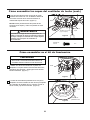
1. Connect the green grounding lead from the
downrod and the green grounding lead from the
hanger bracket to the supply grounding conductor
(this may be a bare wire or wire with green colored
insulation). Securely connect wires with wire
connector. Securely connect the white fan motor wire
to the white supply (neutral) wire using wire connector.
Securely connect the black fan motor wire and blue
wire to the black supply wire using wire connector.
(Figure 2)
NOTE: Optional Remote Control, CR500 is avaiable for
use with this fan—sold separately. If using the CR500,
follow the "How to Wire and Operate Your Remote
Control" section of the CR500 instruction sheet.
NOTE: If you are not sure if the outlet box is grounded,
contact a licensed electrician for advice, as it must be
grounded for safe operation.
NOTE: If you feel that you do not have enough
electrical wiring knowledge or experience, have your
fan installed by a licensed electrician.
How to Wire Your Ceiling Fan
WARNING
To avoid possible electrical shock, be sure electricity
is turned off at the main fuse box before wiring.
(Figure 1)
WARNING
Check to see that all connections are tight, including
ground, and that no bare wire is visible at the wire
connectors except for the ground wire. Do not operate
fan until the blades are in place. Noise and motor
damage could result.
Wire Connectors
HARDWARE USED:
X 3
10
Figure 1
Figure 2
Figure 3
2. After connections have been made, taking care not
to pinch the wires and put the white and green leads to
one side and the black leads towards the other side,
the connection should be turned upward and carefully
push leads into the outlet box. The wires should be
spread apart with the grounded conductor and the
equipment-grounding conductor on one side of the
outlet box and the ungrounded conductor on the other
side.

NOTE: This step is applicable after the neccessary
wiring is completed.
1. Assemble canopy by rotating key slot in canopy
over shoulder screw in hanger bracket. Tighten
shoulder screw. Fully assemble and tighten second
shoulder screw that was previously removed.
(Figure 1)
2. Securely attach and tighten the canopy screw cover
over the shoulder screws in the hanger bracket
utilizing the key slot twist-lock feature. (Figure 2)
How to Install Your Canopy Housing
How to Assemble Your Ceiling Fan Blades
WARNING
To avoid possible fire or shock, make sure that the
electrical wires are completely inside the canopy
housing and not pinched between the housing and the
ceiling.
11
Figure 1
Figure 2
1. Position the blade over the blade holder with
threaded posts showing. Make sure the bottom edge
of the blade is fully seated against the blade holder.
With a phillips screwdriver, tighten 3/16˝-24 truss head
screw with spring washer/flat washer and fiber washer
to secure the blade to the blade holder. (Figure 1)
CAUTION
Do not connect fan blades until the fan is completely
installed. Installing the fan with blades assembled
may result in damage to the fan blades.
Figure 1
Fiber Washer
HARDWARE USED:
X 9
X 9
and Fiber Washers
(3 each per blade)
Blade
Blade Holder
3/16˝-24
Truss Head Screw
With Spring Washer/
Flat Washer
3/16˝-24
Truss Head Screw
With Spring Washer/
Flat Washer

12
How to Assemble Your Ceiling Fan Blades (Continued)
Blade Holder
1/4”-20 Screws
(2 per assembly)
Figure 2
2. Secure the blade holders to the bottom of the motor
assembly using the 1/4˝-20 screws from the hardware
bag. (Figure 2)
NOTE: Periodically check blade holder hardware and
resecure if necessary.
To reduce the risk of personal injury, do not bend the
blade holders when installing, balancing the blades or
cleaning the fan. Do not insert foreign objects in
between the rotating blades.
WARNING
CAUTION
To reduce the risk of electric shock, disconnect the
electrical supply circuit to the fan before installing
your light kit.
X 6
1/4”-20
Screws
HARDWARE USED:
How to Assemble Your Light Kit
Figure 1
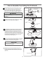
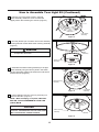
1. Remove one of the three screws in the support
bracket at the bottom of the motor assembly. Retain
the screw for later and slightly loosen the remaining
two screws. (Figure 1)
Motor
Assembly
Motor
Assembly
Light Shade
Assembly
Figure 2
2. Assemble the light shade assembly to the adaptor
plate of the motor assembly using the two key slots
in the light shade assembly. Replace the third screw
and secure all three screws. (Figure 2)

13
How to Assemble Your Light Kit (Continued)
Motor
Assembly
Light Shade
Assembly
Light Shade
Assembly
Figure 3
3. Remove one of the three screws in the light
shade assembly. Retain the screw for later and
slightly loosen the remaining two screws. (Figure 3)
Figure 4
Figure 5
Figure 6
Switch Housing
Assembly
Switch Housing
Assembly
Switch Housing
Assembly
LED Bulb
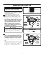
4. Securely attach 9-pin connector from motor assembly
to wiring harness socket within switch housing assembly.
(Figure 4)
5. Assemble the switch housing assembly to the light
shade assembly using the two key slots in the switch
housing assembly. Replace the third screw and secure
all three screws. (Figure 5)
WARNING
The color label on these two connectors must
correspond to each other.
NOTE: When relamping is required, USE ONLY
MAX 6W, TYPE ST48 DIMMABLE LISTED LED
(LIGHT) BULB.
RISK OF FIRE. USE ONLY LED LAMPS IN THIS
LIGHT KIT. INCANDESCENT AND HALOGEN LAMPS
MAY CAUSE SEVERE THERMAL DAMAGE.
CAUTION
6. Install LED light bulb into socket by threading in a
clockwise direction. (Figure 6)

14
WARNING
Check to see that all connections are tight, including
ground, and that no bare wire is visible at the wire
connectors, except for the ground wire. Do not operate
fan until the blades are in place. Noise and fan damage
could result.
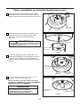
How to Operate Your Ceiling Fan
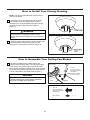
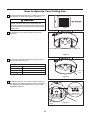
1. Restore electrical power to the outlet box by turning
the electricity on at the main fuse box. (Figure 1)
3. Check the operation of the fan by gently pulling on
the fan pull chain. (Figure 3)
Fan Pull Chain Operating Sequence
1
st
Pull
High
2
nd
Pull
Medium
3
rd
Pull
Low
4
th
Pull
Off
Figure 1
Figure 2
Figure 3
Figure 4
4. Slide the switch to "CH" when use the pull chain to
operate the fan. Slide the switch to "RC" to operate the
fan using the optional CR500 remote control—sold
separately. (Figure 4)
2. Install the fan pull chain and light kit pull chain.
(Figure 2)
Switch Housing
Assembly
Fan Pull Chain
Fan Pull
Chain
Light Kit Pull Chain

15
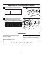
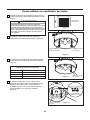
5. Check the operation of the light by gently pulling on
the light kit pull chain. (Figure 5)
Light Kit Pull Chain Operating Sequence
1
st
Pull
On
2
nd
Pull
Begins dimming
3
rd
Pull
Stop dimming
4
th
Pull
Off
Figure 6
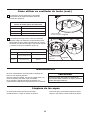
Periodic cleaning of your new ceiling fan is the only
maintenance necessary.
When cleaning, use only a soft brush or lint free cloth to
avoid scratching the finish.
Abrasive cleaning agents are not required and should be
avoided to prevent damage to finish.
Periodic light dusting of the blades is recommended.
A feather duster will work best.
Avoid using water, cleansers, or harsh rags, which
can warp and ruin the blades.
Maintenance
How to Operate Your Ceiling Fan (Continued)
How to Clean Your Ceiling Fan Blades
CAUTION
Do not use solvents when cleaning your ceiling fan. It
could damage the motor or the blades and create the
possibility of electrical shock.
6. If airflow is desired in the opposite direction, turn
the fan off and wait for the blades to stop turning.
Slide the reverse switch on the switch housing assembly
to the opposite position and turn fan on again. (Figure 6)
Reverse Switch Information
Season Rotation Direction Switch Position
Summer Counterclockwise Left
Winter Clockwise Right
Switch Housing
Assembly
Figure 5
Light Kit Pull Chain

16
WARNING
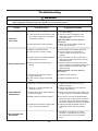
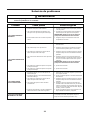
Troubleshooting
For your own safety, turn off power at fuse box or circuit breaker before trouble shooting your fan.
Some suggested remedies require the attention of a licensed electrician.
Trouble Probable Cause Suggested Remedy
1.FAN WILL
NOT START
1. Check main and branch circuit fuses
or circuit breakers.
2. Check line wire connections to fan
and switch wire connections in the
switch housings.
CAUTION: Make sure main power is
turned off !
2.FAN SOUNDS NOISY
1. Attach blades to fan before operating.
2. Check to make sure all screws in
motor housing are snug (do not over-
tighten).
4. Tighten set screw securely.
1. Blades not attached to fan.
2. Loose screws in motor housing.
6. Lower housing support set screw
loose.
3.FAN WOBBLES
EXCESSIVELY
1. Tighten both setscrews securely in
downrod support.
2. Tighten the setscrew in the downrod/
hanger ball assembly.
5. Tighten the hanger bracket screws to
the timber batten, and secure outlet
box.
1. Setscrew in downrod support is loose.
2. Setscrew in downrod/hanger ball
assembly is loose.
5. Hanger bracket and/or ceiling outlet
box is not securely fastened.
4.NOT ENOUGH AIR
MOVEMENT
3.
CAUTION: Make sure main power is
turned off !
Make sure reverse switch position is
all the way to one side.
1. If possible, consider using a longer
downrod. (not included, you can buy
the longer downrod from fanimation.
com).
1. Fuse or circuit breaker blown.
2. Loose power line connections to the
fan, or loose switch wire connections
in the switch housing.
3. Reverse switch in neutral position.
3. Check to make sure the screws which
attach the fan blade holders to the motor
flywheel are tight.
3. Screws securing fan blade holders to
motor flywheel are loose.
4. Check to make sure wire connectors in
switch housing are not rattling against each
other or against the interior wall of the
switch housing.
4. Wire connectors inside housing
rattling.
5. Tighten screws securely.5. Screws holding blades to blade
holders are loose.
3. Check to be sure screws which attach the
fan blade holders to the flywheel are tight.
4. Check to be sure the fan blade holders
seat firmly and uniformly to the surface of
the motor housing. If holders are seated
incorrectly, loosen the screws and retighten.
3. Screws securing fan blade holders to
flywheel are loose.
4. Blade holders not seated properly.

1
2
3
4
5
6
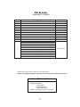
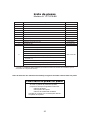
APP799004BL
ADRAC4GT1-45LBN
P767801LBN
APPCP1101LBN
APPCP1403LBN
AMA7678LBN
7
11
10
AP767813LBN
12
HDWLP7678LBN
8
9
AP767805WH
AP767804BU
Fiber Washers (10)
Fan Pull Chain
Wire Connectors (4)
Blade Mounting Hardware Bag Containing:
3/16˝-24 Truss Head Screw With Spring Washer/Flat Washer (10)
Hardware Bag Containing:
Canopy Screw Cover Assembly
Blade Set
Light Shade Assembly
Switch
Housing Assembly
LED Bulb
Blade Holder Set
Motor Coupling Cover Assembly
Motor Assembly
Hanger Bracket Assembly
Hanger Ball/Downrod Assembly
Ceiling Canopy
Light Kit Pull Chain
Pull Chain Containing:
Parts List
Model #LP7678LBN
Ref. # Description Part #
PPJYE26L0600
AP767803BN
1/4˝-20 Pan Head Screws with Lock Washers (7)
Blade Holder Mounting Hardware Bag Containing:
17
Refer to fan model number located on down rod support
Before discarding packaging materials, be certain all parts have been removed.
How To Order Parts
When ordering repair parts, always give the
following information:
• Part Number
• Part Description
• Fan Model Number
Contact your retail store for repair parts.

18
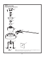
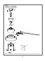
1
2
3
4
5
6
9
10
8
7
12
12
12
12
11
1212
NOTE: The illustration shown is not to scale or its actual configuration may vary.
Product/parts are subject to change without notice.
Model LP7678LBN
Exploded-View Illustration
NAVY
™


2020/12 V.01
Copyright 2020 Fanimation
10983 Bennett Parkway
Zionsville, IN 46077
Phone: 888-567-2055
Outside U.S.: 317-733-4113
FAX: 866-482-5215
FANIMATION.COM
Page is loading ...
Page is loading ...
Page is loading ...
Page is loading ...
Page is loading ...
Page is loading ...
Page is loading ...
Page is loading ...
Page is loading ...
Page is loading ...
Page is loading ...
Page is loading ...
Page is loading ...
Page is loading ...
Page is loading ...
Page is loading ...
Page is loading ...
Page is loading ...
Page is loading ...
Page is loading ...
-
 1
1
-
 2
2
-
 3
3
-
 4
4
-
 5
5
-
 6
6
-
 7
7
-
 8
8
-
 9
9
-
 10
10
-
 11
11
-
 12
12
-
 13
13
-
 14
14
-
 15
15
-
 16
16
-
 17
17
-
 18
18
-
 19
19
-
 20
20
-
 21
21
-
 22
22
-
 23
23
-
 24
24
-
 25
25
-
 26
26
-
 27
27
-
 28
28
-
 29
29
-
 30
30
-
 31
31
-
 32
32
-
 33
33
-
 34
34
-
 35
35
-
 36
36
-
 37
37
-
 38
38
-
 39
39
-
 40
40


Fanimation Studio Collection LP7678LBN Installation guide
- Category
- Household fans
- Type
- Installation guide
Ask a question and I''ll find the answer in the document
Finding information in a document is now easier with AI
in other languages
Related papers

Other documents
-
Fanimation LP7653 AireDrop Pull Chain LED Indoor Ceiling Fan User manual
-
-
-
-
-
-
-
-
-