Page is loading ...

IMPORTANT
THE OUTER CASING, FRONT AND GLASS PANEL BECOME EXTREMELY HOT DURING OPERATION AND WILL RESULT IN
SERIOUS INJURY AND BURNS IF TOUCHED. IT IS THEREFORE RECOMMENDED THAT A FIREGUARD COMPLYING WITH BS
8423 (LATEST EDITION) IS USED IN THE PRESENCE OF YOUNG CHILDREN, THE ELDERLY OR INFIRM.
Do not attempt to burn rubbish in this appliance. Please read these Instructions carefully before installation or use.
Keep them in a safe place for future reference and when servicing the fire.
The commissioning sheet found on page 3 of these instructions should be completed by the Installer.
PM1764.4.02.2021
Vogue 700
Inset Convector Fire
Installation Instructions

2
Covering the following models:
Vogue 700 - Inset Convector
Installation Instructions ............................................4
Essential Information .................................................................. 4
Dimensions .................................................................................6
Clearance Dimensions ............................................................... 7
Hearth Information ......................................................................9
Declaration of Performance......................................................10
Pre-installation ..........................................................................12
Smoke Control Settings............................................................16
Installation ................................................................................18
Commissioning ......................................................................... 28
Maintenance & Servicing ........................................29
Spare Parts List ........................................................................33
Information Requirement - Solid Fuel ..................................... 34
Service Records ....................................................................... 35
Appliance Product Code
Vogue 700 323-007
CONTENTS
Data Plate
The serial number is required when
ordering spare parts or making
warranty claims.
This is on a plate on the inside of the
door.
The CE Data plate is found behind the
door by the Air Control.
SERIAL NUMBER
Serial Number Plate

3
Dealer appliance was purchased from:
Name:
Address:
Telephone number:
Essential information - MUST be completed:
Date Installed:
Model Description:
Serial Number:
Installation Engineer:
Company Name:
Address:
Telephone number:
Commissioning Checks - to be completed and signed:
Is flue system correct for the appliance:
YES NO
Flue swept and soundness test complete:
YES NO
Smoke test completed on installed appliance YES NO
Spillage test completed YES NO
Use of appliance and operation of controls explained YES NO
Clearance to combustible materials checked YES NO
Instruction book handed to customer YES NO
CO Alarm Fitted YES NO
Flue draught Reading (Pa) HOT COLD
Signature: ............................................................................ Print Name: ..........................................................................
To assist us in any guarantee claim please complete the following information:-
APPLIANCE COMMISSIONING SHEET

4
GENERAL
Model:
Vogue 700
Vogue 700
Nominal Heat Output Wood kW 7.0kW
Efficiency Wood % 77.0
CO @ 13% O
2
Wood % 0.07
Weight Kg 116
Recommended Fuels
Wood
Seasoned Wood
(less than 20% moisture content)
As tested to the requirements of EN 13229 for intermittent operation
FLUES
Flue/Chimney Size
With Liner of Factory made system
(diameter)
installed in accordance with manufacturers
instructions
mm 153
inch 6
Flue/Chimney
minimum height
All products
m 3.5
feet 15
Flue Draught
Min
Pa
10
Nominal
12
Max
20
Flue Gas Mass Flow Wood g/s 5.9
Average Flue Gas
Temperature
Wood
o
C
308
Flue Outlet Size
(Top Option)
mm 153
inch 6
European Min Spec for Solid Fuel Chimney Flue - T400 N2 D 3 G50
VENTILATION
A) Traditionally Built Homes
• Where leakage is greater than 5m
3
/hour/m
2
.
• Ventilation normally required = 550mm
2
per kW output over 5kW
B) Modern Construction Homes
• Where leakage is less than 5m
3
/hour/m
2
.
• Ventilation normally required = 550mm
2
per kW
A
Additional Ventilation
mm2 1100
cm2 11.0
in2 41.3
B
Additional Ventilation
mm2 3850
cm2 38.5
in2 151.6
ESSENTIAL INFORMATION

5
Installation
Registered Professional:
Before installation and/or use of this appliance please read these instructions fully and carefully to ensure that you have fully understood their
requirements.
The appliance must be fitted by a registered installer, or approved by your local building control officer.
Structural Support:
If installing on a wooden floor check that the floor joists are strong enough to bear the weight of the insert, chimney and construction parts.
Hearth:
A Constructional Hearth with a depth of 125mm and a 12mm Decorative Hearth Plate must be installed to protect a combustible floor from the
risk of falling embers if mounted directly on the floor.
The Decorative Hearth must extend 300mm in front of the hearth and can be made of natural stone, concrete, metal or glass.
Final inspection of the installation:
When it has been installed, the appliance must be commissioned in accordance with standards and practices to ensure full working order and
a correct handover given to the customer.
Flue and Chimney
The flue or chimney system must be able to withstanding flue temperatures of up to 400
o
C.
The external diameter of the connection sleeve is 155mm.
In normal operating mode, draft in the chimney should be 20-25 Pa close to the connection sleeve. The draft is affected primarily by the length
and area of the chimney and also by how well sealed it is.
The minimum recommended chimney length is 3.5m and a suitable cross-section area is 150-200cm² (140-160 mm in diameter).
Sharp bends and horizontal lengths in a flue pipe reduce the draft in the chimney.
It must be possible to sweep the full length of the flue, and the soot doors must be easily accessible.
Carefully check that the chimney is sealed and that there is no leakage of smoke from the connections.
Combustion Air Supply
When the appliance is installed, it is essential to ensure adequate air is supplied to the room. Air can be provided indirectly via a vent in the
outer wall or via a duct from the outside that connects to the sleeve on the underside of the insert. The required volume of combustion air is
about 20 m3/hour.
The outer diameter of the combustion air connection sleeve is 65mm.
If a pipe is longer than 1 m, its diameter must be increased to 100mm and a larger wall vent will be required.
In heated spaces, the flue must be insulated to prevent condensation using 30mm mineral wool covered with a vapour barrier. The hole in the
wall (or floor) at the exit point must be properly sealed with flue jointing compound.
A flexible pipe to provide external directly into the appliance is available and must be fitted at the time of installation.

6
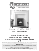
VOGUE 700 DIMENSIONS
All dimensions in mm. (25.4 mm = 1”)
Description Model A B C D E F G H
J
K L M
Vogue 700
323-007 802 586 576 324 363 346 143 76.5 542 368 736 155
A
B
K
L
Ø M
C
Viewing Area
D
Viewing
Area
G
H
I J
F
E

7
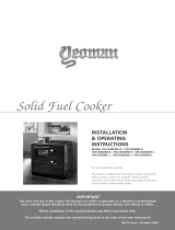
MASONRY/NON-COMBUSTIBLE INSTALLATION
Min 10mm Air Gap
Min 200mm
See Hearth
Section
No Combustible
Material in this area
CLEARANCE DIMENSIONS
10mm
10mm
500
500
10mm
Unprotected Combustible Material
Protected Combustible Material
3 x D Ø
1.5 x D Ø
Make sure that the connected flue system is positioned at
a reasonable distance from any combustible material.
Stovax recommend the use of a flue liner when installing
into a masonry chimney. Alternative methods can be used
if the chimney is sound and correctly sized, however
access may be required to make an effective seal - ie
Using a sump adapter.
Stovax recommend using an approved twin wall insulated
chimney system when installing within studwork.
FLUE CLEARANCES
500
50
20
20
Non-combustible (Calcium Silicate) board

8
To achieve these distances all combustible material must be covered
with non-combustible material such as Calcium Silicate Board or
removed from the area.
CLEARANCE DIMENSIONS
MINIMUM DISTANCE TO COMBUSTIBLE MATERIAL
20
20
50
500
20 mm Luftspalt
500
20
50
20
50
20 mm Luftspalt
900
700
20
max 100
50
20
100
1100
300
Area ut min. 200 cm
2
Area in min. 200 cm
2
20 mm Luftspalt
Lastbärande sockel
Avtätning
Load bearing base
Area in min. 200cm
2
Area out min. 200cm
2
Sealing
20 mm Air gap
20 mm Air gap
20 mm Air gap
max 100
20
100
100
500
Wall made of combustible material
Aerated wall, comprising at least a 50 mm calcium silicate board
and an air space. There must be a 20 mm air space between the
building board and the combustible wall. The air space must allow
air to flow freely along the lower and upper edges (see diagram to
the right).
Diagram of aerated wall
Two calcium silicate board battens
ensure that the air space is
maintained.
20

9
Dimension
A
(Min)
B
Vogue 700 1775 300
A
B
*Stovax recommends that the depth
of the Decorative Hearth is equal to or
greater than the height of the appliance
from the floor, OR, the length of the
door from the wall when in the open
position.
USE WHICHEVER FIGURE IS GREATER.
125mm hearth thickness
(Constructional and Decorative combined)
12mm thick
Decorative hearth
If installed at a height above 600mm from the floor
there is no need for a constructional hearth in front
of the appliance.
HEARTH DIMENSIONS
GENERAL INFORMATION
Installing the Appliance
Each installation is unique to the property so it is not possible to
give details to suit every setting.
The installation must comply with Building Regulations and be
made using "best practice" construction methods.
Take care when installing the appliance. Careless handling
and use of tools can damage the finish and/or area.
There are 2 types of installation for this appliance:
1. Studwork Installation
2. Fitting to a Masonry Chimney
Appliance Location
This appliance sits in a recess, all nearby walls that are not
classed as re walls or are considered unsuitable for exposure to
heat must be protected by non-combustible building material in
accordance with the specications below.
Seal all joins in the non-combustible material using the method
recommended by the manufacturer.
Ventilate the space between the insert and the recess as specied
in these instructions.
Refer to the manufacturer’s installation instructions when
connecting the chimney system ensuring that the distance to
combustible materials are maintained.
Ensure all combustible materials are not placed closer than 1m
from the front of this appliance.
The appliance must be installed with clearance to the building
material, not in direct contact with it, to allow for thermal expansion
of the insert.
Ventilation
Do not pack the void around or above the appliance with insulation
materials such as mineral wool or vermiculite.
The void built for the cassette must be ventilated to prevent a build
up of heat. If the void is sealed then you must fit vents at both low
and high levels of approximately 20cm
2
each. These vents must
take cold air from the room and return warm air back into the room.
An access hatch must be left in the side of the chimney breast for
future servicing and inspection of the flue and appliance.
Building Materials
Stovax recommend building the enclosure from the following
materials:
Metal Studwork
Non-combustible board: Calcium Silicate Board - NOT PINK
BOARD
Heat Resistant Plaster: Purimacho (any spider cracks that develop
after installation will need to be rubbed down and relled with
Purimacho heat resistant ller to stablise).
Ensure all distances to combustible materials are maintained

10
CO PM OGC
NO
X
CO PM OGC
NO
X
(%)
(%)
0.07 25 84 95 -- -- -- --
--
500 mm
90 mm
340
PM1031 DoP Form Issue 10
24/03/2020
Ian Kingscott - Group Technical Director
This declaration of performance is issued under the sole responsibility of the manufacturer identified in point 4.
Signed for and on behalf of the manufacturer by:
16 April 2020
Exeter -
77
308
ΣC
--
ΣC
10. The performance of the product identified in points 1 and 2 is in conformity with the declared performance in point 9.
kW
kW
Distance to combustible materials
Follow the given conditions in the installation Instructions
Maximum operating pressure
bar
Minimum distances
Side
Rear
Fire Safety
Reaction to fire
Risk of burning fuel falling out
Pass
Pass
EN 13229:2001/A2:2004
Performance
Electrical safety
Cleanability
Mechnical resistance (to carry a flue / chimney)
(mg/Nm
3
@ 13% O
2
)
Pass
Pass
Pass
Pass
Thermal output
Nominal heat output
Room heating output
Water heating output
Energy efficiency
Wood
Briquetted solid fuel
Flue gas temperature at nominal heat output
Surface temperature
(mg/Nm
3
@ 13% O
2
)
kW
%
--
%
--
kW
kW
kW
--
--
--
Haromised technical spefication
Essential characteristics
Emission of combustion products
7
7
9. Declared performance:
N/A
6. System or systems of assessment and verification of constancy of performance of the construction product as set out in Annex V:
System 3 & 4
7. In case of the declaration of performance concerning a construction product covered by a harmonised standard:
The notified laboratory RRF - No. 1625 performed the determination of the product type on the basis of type testing under system 3 and issued test
report RRF - 29 20 5506
EX2 7LF
United Kingdom
Tel: +44(0)1392 474000
Email: [email protected]
www.stovax.com
5. Where applicable, name and contact address of the authorised representative whose mandate covers the tasks specified in Article 12(2):
Inset roomheater burning solid fuel without hot water supply
4. Name, registered trade name or registered trade mark and contact address of the manufacturer as required pursuant to Article 11(5):
Stovax Limited
Falcon Road
Sowton Industrial Estate
Exeter
Stovax Riva2 : Inset roomheater burning solid fuel without hot water supply
2. Type, batch or serial number or any other element allowing identification of the construction product as required pursuant to Article 11(4):
Vogue 700 : 323-007
EN 13229:2001/A2:2004
3. Intended use or uses of the construction product, in accordance with the applicable harmonised technical specification, as foreseen by the
manufacturer:
323-007
DECLARATION OF PERFORMANCE
according to Regulation (EU) 305/2011
1. Unique identification code of the product type:

11
1
2
4
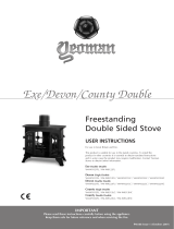
PARTS IDENTIFIER
To make the installation of the appliance easier it is best to remove the internal components before fitting into the builders opening/studwork.
1. Flue Connector
2 Firebricks (Vermiculite)
3 Grate
4 Dataplate
3

12
PRE-INSTALLATION
1
2
4
3

13
PRE-INSTALLATION
10
9
5
6
7
8

14
12
11
13
PRE-INSTALLATION
15
16
14

15
PRE-INSTALLATION
20
19
17
18
21

16
Mandatory for smoke control areas
SMOKE CONTROL AREA SETTINGS
IMPORTANT:
The Vogue 700 has been recommended as suitable
for use in Smoke Control Areas when burning wood
logs and operated in accordance with the User
Instructions.
The permanent stop must be installed if the
appliance is to be used in a Smoke Control Area.
This stop must not be removed otherwise an offence
will be committed if the appliance is used without
the permanent stop in place.
1
2
3
4
5

17
SMOKE CONTROL AREA SETTINGS
6

18
INSTALLATION
BUILDERS OPENING
The Vogue 700 is designed to be installed in existing approved open hearths or studwork chimney breasts.
There must be an 10 mm air gap around the insert, to allow for the expansion of the insert when hot.
Build the chimney breast to support the cassette.
Ensure all clearances to combustible material are maintained, see Clearance Section.
To prevent cracking ensure no joints above the appliance.
Ensure all clearances to combustible materials are maintained.
Line a recessed chamber with Silicate Board to the sides and rear (see Clearance section).
Fit vents at high and low levels with a minimum area of 200cm
2
.
755
565
370
Min
300
MASONRY INSTALLATIONS
STUDWORK INSTALLATIONS
Studwork Installation:
It will be necessary to vent
the chamber at high and
low levels.
Vent size 200cm
2

19
INSTALLATION
1
2
3
Insert ue liner through an
adjustable locking band and
secure to the ue adapter.
Tighten locking band.
Adjustable Locking Band
ALL INSTALLATIONS

20
INSTALLATION
EXTERNAL AIR KIT
Stovax Part Number: 323-900
The following steps must be done prior to installation to use the
Vogue 700 with a Stovax Dedicated External Air Kit.
i
ii
iii
iv
v
vi
/