
;;H;"
AovENruRE&p
sQ-5016 / SM-50'16
OPERATION
MANUAL
(English
& German
versions included)
DtN EN t809001
Certificate NO:09
'!00
89126
.
äart|h
NIn
btlll tl lfi
w
GREEN PRODUCT
It
has
be€n RoHS Compliant

General
Congratulation
for owning
this all-inone
portable
sound system. Please
read ttris operating
instruction
thoroughly
to fully understand
its
controls and functions.
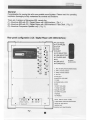
There
are
4
versions
of Adventure
800, namely
the
(1).
Adventure
800 with
CD / Digital Player
with USB-tnterface.
(
Fig. 1
)
(2).
Adventure
800 with
CD / Digital Player
with
USBJnterface & Tape
Deck.
(
Fig. 2
)
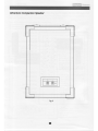
(3).
Adventure
Companion
Speaker only.
(
Fig.
3
)
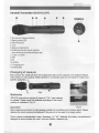
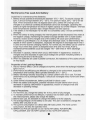
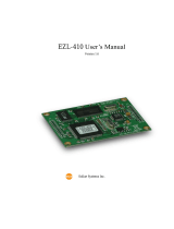
Rear
panel
configuntion
(
CD / Digital
Playerwith
USB-lntefiace)
A
LCD Display
B
PLAY/PAUSE
A
STOP
E
SKIP
E
EJECT
E
CD
SELECTOR
G
USBSELECTOR
H
FOLDER
SKIP
trtR
I
USB INPUT
E POWERA/OL,
CD
player
remole contol.
1. MrC rN
(BALANCE/UNBALANCE)
2. WRI
channel selector
3.
WR2 channel sel€ctor
4. AUX IN
s.AUX OUT
6.MASTER
VOLUME
7.FUSE
S.POWER
(ON
/ OFF)
9.MtC
1O.WR1
VOLUME
11.WR2VOLUME
l2AUXVOLUME
13.TAPE VOLUME
14.BASS
15.TREBLE
16AC
INPUTJACK/FUSE
1 T.BATTERY
STATUS INDICATOR
18.DC
24-32V TNPUT
19.SPK
OUT
20.sPK
OUT
(SWTTCHED)
/1o
ttrl
o\-,/
o.
r'#:
r.iE'
€
re
l(o
)
U
Eo
f--l€
E]
o
Erö
!.Ö
C--
traö
(a
rye
---
10
Erh
b;r
IZ E
IEE
"
goo
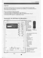
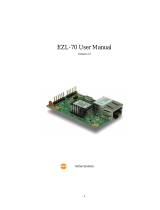
Flg
1.

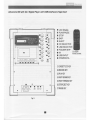
Adventure 800 with CD / Digital
Player with
USBln|'crtace
& Tape Deck
A
LCD Display
13
PLAY/PAUSE
O
STOP
E
SKIP
E
EJECT
E
CDSELECTOR
G
USB SELECTOR
H
FOLDER SKIP
Ir
tR
I
USB INPUT
A POWER/VOL.
2l.CASSE|IE
CoVER
z.RECORD KEY
23,PI.AY KEY
24.FASTREWIND KEY
2s.FASTFORWARD KEY
26.STOP/EJECT KEY
27,PAUSE KEY
CD
player
remote control.
a
/-\o
(tr)
o\--l
-,
r'#i
r;&
€
r@
n@
'd
rC)
r-r
€
E]
uö
u@
S--
nf$)
r
(ö
o
ryö
---
YO
EA
r:r
E
IE IPE
"
goo

Adv
entu
re
Co m
pan
i
o n Speaker
E

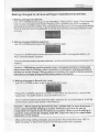
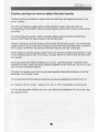
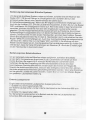
The Power
Supply and
basic Battery Management
The
power
supply of Adventure 800 system comes from
the two
pieces
of
12V
|
4.5 AH
built-in rechargeable batteries
(
maintenance free
Lead Acid type, which has no memory
effect
)
. An
understanding and
knowledge of rechargeable battery is imperative in the
operation of the
portable
sound system as it helps to
give
a trouble-free operation of this
system.
After
unpacking the unit for the first time,
please
charge the
rechargeable
batteries
in
the
system first for at least 10 hours before any operation.
This is
a
very important
procedure
that user MUST undertake in order to
get
the
longest
life
span out of
the
batteries.
Failure
to
follow this
proper
battery management
instruction may cause the user end up
paying
for
new batteries.
The rechargeable batteries
were
fully charged in
the factory
before shipment.
However, the
unit
you
have
just
unpacked
could have been several months old and the built-in lead acid
rechargeable batteries might have been discharged or drained. This
is
analogue of car
which has been left unused for months and the restart is impossible due to flat battery. lt is
thus imperative that
a
full
charge
is
absolutely
necessary for
a
new
system or system left
unused
for
several months.
To
charge the battery, simply
plug
in the
AC
supply and the charging
process
will
start
automatically and
the
battery status
indicator will flash. When
permanent
Green light
appears, it means the batteries are fully charged. Normal operation could now be resumed.
When the charging indicator lights up in
RED,
it means battery
is weak
and charging is
required.
In
an urgent case when the system must be used
while
the system is still under
charging, for this system it is
still
possible
as
the AC
power
supply
is designed
such
that it
also
provides
the
power
for
the system
while
charging
the
batteries
but
this could only be
done when the charging
process
has started for about 5 minutes and some minimum
energy has
been stored
in
the batteries.
4

Operating the Wireless Microphone
System
To use the First
wireless system, switch on the
receiver
module
power
supply switch of WM
1 .
Switch on the corresponding
matching transmitter or handheld microphone
(
please
refer to the
operating instruction
of the individual transmitter
).
When RF signal is being received by
the
receiver,
the receiver RF
signal
indicator 1 will
light up.
Rotate
the control
WM1
and MASTER
volume
control
clockwise
to
increase the volume. When voice is spoken inlo the microphone,
amplified
sound should be heard over the built-in sDeaker.
This instruction
is for system which
is equipped with
two
wireless receiver modules. To use the
Second wireless system,
switch on the receiver module
power
supply switch WM2. Switch on
the corresponding
matching transmitter or handheld microphone. When RF
signal
is
being
received by
the
receiver,
the receiver RF signal indicator 2 will light
up.
Rotate
the
WM 2
control
and
MASTER
volume control
clockwise
to
increase the level. When voice is spoken into the
microphone,
amplified sound should be heard
over
the built-in
speaker.
Operating the Wired
/ Cable
Microphone
To use the
wired microphone, simply
plug
in the
wired microphone connector into the XLR /
Phonejackcomboconnector,ThisuniqueconnectoraccepteitherXLRorl/4
PhoneJack
male connector. Rotate
the MIC In volume control and MASTER Volume control clockwise
to
increase
the volume. When voice is
spoken
into
the
wired microphone,
amplified sound should
be
heard
over the built-in
or external speaker.
Both wired
and wireless microohone
could be used simultaneouslv as
there is
a built-in mixer
to
mix both input
signals.
When all the levels
are set, simply use the MASTER volume control
as
main
control.
Function
of Speaker out
There
are two types
of Speaker out
jack.
Speaker
out
(
unswitched
)
When
an external speaker
is
connected
to this
oulput, both the
internal
speaker of
and
the
external speaker will have sound,
Speaker
Out
(
switched
)
When an external speaker is connected to this output, the internal
speaker will
be muted and only the external speakerwill
have
sound.
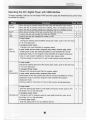
E

Operating
the
CD /
Digital Player
with
USB-lnterface
To begin operation,
first turn
on
the
Master PWR
and
then
press
the Power/Volume
control knob
to activate this
player.
this
key is
pushed
during CD stop,
play
will
start after hack
search.
When
this
key
is
pushed
during
CD is
playing,
then it is
changed to
pause.
When
CD is not
if this key is
pushed
then
CD will
this will
chanqe the mode
to CD-MP3.
this
will chanqed the
mode to USB.
SKIP+
UP/CUE
ln stop mode:
Change the
starting
play-track(file)
during stop mode,
cyclic to the first
if
it is in the last
track.
In
program
entry mode:
Change to the next track(file)
for
program
select .
In
play
mode,
pause
mode,
program play
mode, random
play
mode:
Single
press
to skip the
playing
track(file) to next track(file)
for normal
play/pause
mode, to next
program
index track(file) for
program play/pause
mode, to next random
track(file) for random
play
/pause mode.
Continue
press
for more than
0.7 sec to fast fonrvard
during
play/pause.
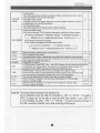
SKIP-
DONWREV
In stop mode:
Change the starting
play-track
(file)
during stop
mode, cyclic to the last
if it is in the first track.
ln
program
Entry mode:
Change to the
previous
track
(file)
for
program
select.
ln
play
mode,
pause
mode,
program
play
mode:
Single
press
to skip the
playing
track
(file)
to
previous
hack(file) for normal
play/pause
mode, to
previous program
index track(file)
for
program
play/pause
mode.
Continue
press
for more
than 0.7 sec
to
fast reverse
during
play/pause.
FOLDER
In
stop mode:
Skip the starting
play
folder
to
next folder
during stop mode,
cyclic
to the
first folder
if it is in the last folder.
In
program
entry mode:
Change the file for
program
select to next folder's
first file, cyclic
to the
first
folder if it is in the last
folder.
ln normal
play
mode:
Skip the
playing
file
to the next folder's
first file.
E

FOLDER.
DOWN
ln stop mode:
Skip
the
starting
play-folder
to
previous
folder
during stop mode, cyclic
to
the
last
folder if it is in the first folder.
ln
program
entry mode:
Change the file for
program
select to
previous
folder's first file, cyclic to
the
last folder if it is in the first
folder.
In normal
play
mode:
Skip the
playing
file to
the
previous
folder's first file.
PLAY MODE
In mp3 and
USB
mode .
lf this key is
pushed,
PLAY mode is changed cyclically
as shown
below.
>PLAYALL RANDOM
-+
REPEAT TRACK
-+
REPEAT FOLDER
I
L
REPEATALL<-
RANDOM REPEAT<- PLAY ALL-
lN
CD mode lf this key is
pushed,
PLAY mode is changed
cyclically shown below
r>
P LAY ALL
RAN
DO M
-----)
R E PEAT TRACK
-----------
I-
REPEATALL<-
RANDOM REPEAT<_ PLAYALL.+
EJECT
When this kev is
oushed.
door
is moved out.
PROG
Set to
programming
mode.
ln nrnnrqmminn mnr{a if Ic}nnl lrarr ic nrrcharl lhan nrnnram ic all nlaarad
MUTE
When this key is
pushed
during
CD
is
playing,
the
set
will mute the
outpu
Push aoain to recover the outout .
option
- PUWET{
'ower
SW of the
set
.
ESP
ln
CDDA mode, Press"ESP" key
,
then
ESP
display
will
be lighted and the
in electronic anti-shock state.
The electronic anti-shock time is about 40
seconds.
Press "ESP" kev aoain to cancel the ESP function.
;et is
FIND
In MP3 mode :
Press
this
key once to change FILE search mode.
Press
this key twice to
change ALBUM search mode.ll
press
this key long
time
once track
is
displaved .press
twice
ld3 TAG is
displaved.
0-1 0; You
can use these
kevs
to select the track
vou
want
directlv.
VOL.-
When
this key is
pushed,
thevolumewill decrease by 1dB
perstep,
the min. volume is OdB.
ENCOOE
VOL.+
When
this key is
pushed,
the
volume will increase
by 1dB
per
step
,
the
max. volume is 30dB.
ENCOOE
Caution: This
player
does not accept
8-cm diameter CD.
User is advised
to
have
the USB 2,0 formatied in
"
FAT
"
or
"
FAT 32
".
The
built-in
USB 2.0
player
can
not
be able to read the MP3 files stored in
your
USB if
it
is not
formatted by either
"
FAT
"
or
"
FAT-32
",
To avoid
possible
damage
to
the USB, remember to detach it
only after switching off the
player.
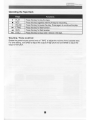
z

Operating
the Tape Deck
Press
this key to
play
the tape.
Press this key with
PLAY kev for record
Press this key to
pause
the
plav.
Press aqain to
continue the
olav.
Press this
key for fast forward .
Press
this key for fast reverse.
Press this kev to stoo
/ slot / remove the
Voulme
/ Tone
control:
Rotate
the
power/volume
control knob
of
TAPE
to adjust the volume
of the Cassette
deck.
For
tone setting, turn
BASS to adjust the
output of high
pitch
and
turn
BASS to
adjust the
output of low
pitch.
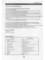
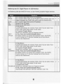
E

Sim
ple
DIY
Trouble-shootings:
1. No
sound when speaking
into the wireless microphone
Please verify
the followings :
1.1 Main
power
switch should be
ON.
When
no
light
appears,
it means
that the battery is
weak.
Please
plug
in
the AC cable to charge the battery.
1.2 WM1 should
be switched on. When two wireless microphones
are
used,
both
WM1
and
WM2 should
be switched on. When
this is done,
please
verify that the MASTER
volume
control
is
been used
to adjust to the desired volume.
1.3 Wireless
microphone
should be
put
to ON and verify that the battery
is
O.K.
(
please
refer
to wireless
microphone
operating manual
)
and observe the
RF
signal
received
on the
RF
indicator 1 or 2.
1.4 Please
verify
that the frequency on the wireless microphone and the corresponding
built-in wireless receiver
module are exactlv the same.
2.No
sound
when
CD / Digital Player *nn
,r"anrerface
or Tape Deck is
used.
2.'1 Main
power
switch should be ON. When no light
appears,
it means
that the battery
is
weak.
Please
plug
in
the AC cable to charge the battery.
2.2 Please
make sure that if both the Master PWR
and
the designated PowerA/olume
control
are switched on. lf either
PWR
isn't
turned on, the module won't function.
2.3 Follow the
proper
operating instruction of CD / Digital Player or
Tape
Deck.
No
power
supply
1.Battery is
faulty
2.Battery is
not charged.
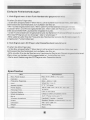
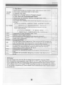
Specification
Item
Speclfletlon
Max.
Power
Outout
Max.75W(RMS)/4Q Load
Distortion
<
O.5o/o
Frequenry Response
SOHZ-2OKHZ13dB
Input
Wired Mic / Lina ln
SDeaker Svstem
6*9"full
range
PÖwar Sl rnölv
12OV I 23O VAC 3A ot 24
-
35 V
DC
Recharoe'I'ime
1O Hours
,
-Re.c.eive..r--Medule-.."
\A/ired
micrcohone
UHF or VHF band
Chiayo
or
other compatible brands
Mic ln
XLR / Phone Conbo
jack'
1
Handheld / Lavalier / Headset
Output
Speaker/ Speaker out(switchedy Line out
Dimension
44O
"
21O' 25O mm
Weisht
About 20 Kg
BlackColor
g

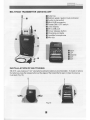
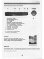
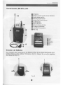
Handeld
Transmitter SQ601 6:(UHF)
l.Microphone
Capsule
module
2.Battery status LED
3.ON/OFF switch
4.LCD
5.Battery compartment
6,Rotating
protective
cap for controls
(also
serves as color ldentification cap)
7.LOCK / unLOCK
8,SET
9.UP
1.0.D0wN
11 .Gharging
port
12.Name olate
Changing
of capsule
First unscrew
the
metal
grill
fom the
housing
and take
out the capsule to
be
replaced
(Fig.9).
Then insert
in a new capsule. Either dynamic or condenser
type
can be chosen to match
your
-*"ö
SQ-5016
microphone requires 2
pieces
of
"
AA
"
size batteries
to operate. Please insert the batteries acmrding to the mnect
polarity
as indicated in Fig.10.
Caution
Many batteries are known
to
have leakage
problem
of conductive and conosive liquid.
Please
observe
the
rule to remove the batteries if they are not
to
be used
for
a longer
period.
Due to various
unstandardized sizes
(
diameters
)
of
'AA'
batteries, this battery compartment is
designed to accommodate the most common Alkaline batteries only.
@o@@
0
\].LIJ
m
EIE]!:ß-
rllr|lii[st
w.
I
@
Fig.10
m

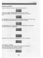
Making
changes
to
various
settings
in handheld
transmitter.
l.Making changes
to
Ghannel:
Use
UP or
DOWN button
to
go
to the CHANNEL/
FREQUENCY
page.
The cursor
will
flash to allow
changes
to be
made.
Pressing
UP or
DOWN
button
will increase
or
decrease
the channel
number.
The corresponding
frequency
will change
accordingly.
When a desired
channel
is selected,
it
will be
automatically
saved
and stored
in the
memory.
2. Making
changes to
Battery
selection:
Use UP or
DOWN button
to
go
to the Battery
selection
page.
Press UP or
DOWN button
to move
the cursor
to
either
NiMH
(
rechargeable
battery
)
or
AKLN
(Alkaline
battery
)
position.
When the desired
battery
has been
selected,
it
will be automatically
saved and
stored
in the
memory.
Remark
: NiMH battery
must
be selected
when
rechargeable
battery
is being
used.
Never select
AKLN
(
Alkaline
)
when transmitter
is intended
for
charging
as Alkaline
battery
can
not
be
charged
I Wrong
selection
of battery
will
result in battery
sensing
electronics
to display
wrong
and misleading
status
information.
3.
Making changes
Use UP
or DOWN
to Sensitivity
Level:
button
to
go
to the SENS
SET
Page.
Press UP or
DOWN button
to
increase
or decrease
the Sensitivity
Level of
the
transmitter.
The MAX
level
is 4 and
the
MIN level
is
1.
When a
desired sensitivity
level
has been
selected
for
your
application,
it will
be
automatically
saved
and
stored in
the Memory.
Remark
: When selecting
Sensitivity
level,
please
bear
in
mind that
Level
1
is
for
close
proximity
singing
purposes whereas
Level
4 is for use
of
transmitter
ön tripod
mount
for speech
purposes.
When
Level
4 setting
is
used
for close
proximity
singing,
high SPL
input will
result
in undesirable
distortion
in the output.
After
performing
setting
changes,
you
could
turn the
protective
cover
180"
in
either direction
to block
the buttons
from
being
accidentally
adjusted.
m

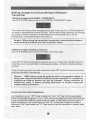
BELT-PACK TRANSMTTTER
(SM.501
6) UHF
ll
Antenna
E
Battery weak / audio mute indicator
E
Audio mute switch
E
Mini-XLR connector
E
Power ON / OFF switch
E
LCD display
E
Mini USB
port
E
Cover release button
El
Charging contacts
lE
Lavalier microphone
lIIMic
clip
IE SET
IF
UP
G
oowlt
MGT
GMr
I NSTALLATION
OF
BATTERIES
SM-5016
uses2piecesof"AA"sizebatteries(Alkalinebatteryisrecommended).Toinstall
orremove
the batteries,
press
the release buttons at the edges of the transmitter lo open or close the cover as
illustrated
(
Fig.15
).
Fig.15
I
I
./- \
I:':,:lC::1Ai}Jil t
Itr'@tl
m
M

Making
changes to various settings in Beltpack
Transmitter.
l.Making
changes to CHANNEL / FREQUENGY:
Use UP
or DOWN button to
go
to the CHANNEL/FREQUENCY
page.
The cursor will flash
to allow changes
to
be made. Pressing UP or DOWN button will
increase
or decrease the
channel
number. The
corresponding
frequency
will change
accordingly.
When a desired channel(frequency) is being
selected,
it will
be
automatically
saved and stored
in the memory.
Remark : When changing transmitter frequencies,
care should be taken to
avoid causing
interference to other channels
/
users.
2.Making
changes
to
Battery
selection:
Use
UP or
DOWN
button to
go
to the Battery selection
page.
Press
SET for about 2 seconds to activate the cursor. Press
UP
or
DOWN button
to
move
the cursor to either NiMH
(
rechargeable
battery
)
oTAKLN
(
Alkaline
battery
)
position.
When the
desired option has been selected,
press
SET for
about
2
seconds
to
save
and
store the data
in
the memory.
Remark : N|MH
battery must be selected when rechargeable battery is
being used.
Never
select
AKLN
(
Alkaline
)
when transmitter is intended for
charging
as
Alkaline
battery can not be charged I
Wrong
selection of
battery will result in
battery sensing electronics to
display wrong
and
mislead status information.
3.lnput Level
Gain Control Adjustment
Low impedance
(
Lo-Z
)
" MT'& high impedance
(
Hi-Z
)
'GT'gain
controls
are situated
inside
the transmitter as shown in Fig
10. Gain
controls
are adjustment
ports
that enable
you
to use microphones
of difiering outpul levels and Guitar or instruments with Hi-Z output. To
adjust microphone
(
Lo-Z
)
input
levels,
turn the
"
MT"
control and to adjust the Guitar or
instrument
(
Hi-Z
)
input,
adjust
the "
GT"
gain
control
to
set
the transmitte/s
desired audio
inout level.
TE

Caution and tips on
how
to obtain the best
resulfs
l.Before inserting
the batteries,
please
make
sure that they are
inserted according
to the
correct
polarity.
2.For PLL-'16-frequency agile version, before operation
please
make sure that the
corresponding receiver MUST have the same frequency
group
and channel number
as
the
transmitter.
3.For fixed frequency version, before operation
please
make sure that corresponding
receiver
MUST have the same frequency as the transmitter.
4.Before making any channel change,
please
switch off the
power
supply. The synthesized
program
works in
such a
way that
a
change
of
channel will only take
place
after a
power
off
and on action.
Otherwise,
the
previosly
selected frequency will stay unchanged.
5.After making a channel change,
please
make sure that the corresponding change is made
on the matching receiver also. To be exact, changes MUST be made at both the transmitter
and receiver.
6.Use only brand new Alkaline batteries. Do not use "
general purpose
" batteries. When
batteries
are
weak, replace
the three batteries altogether at
the same
time.
Do not mix
and
use new
and old batteries together.
T.Position the receiver
such
that it has the least
possible
obstructions
between it
and
the
transmitter.
Line of sight is best!
8.The transmitter and the receiver should be as close as
possible
but not less than 1m.
9.4 receiver cannot
receive
signals from two or more transmitters simultaneously.
1O.Turn
the transmitter off
when it is not in
use.
Remove the bafteries if it is not to
be used
for a
period
of time.
@

Maintenance-free
Lead Acid
battery
Guidelines for maintenance-free Batteries:
1. Battery should
operate at temperatures between 15"C
-
50"C.
To
ensure a
longer life
span, it should be kept
between 5"C
-
35"C.
For
optimum
result, 20'C
-
25'C will
be
ideal. When
temperature
falls
15 degrees below zero, battery
will
undergo some
changes in
its
chemical contents and therefore cannot be recharged. Operating the
battery at higher
temperature
will result in higher capacity but shorter lifespan, whereas
lower temperatures
operation has a longer lifespan but less capacig.
2. lf the battery is not recharged
72
hrs after it is completely used, it will be
permanently
damaged.
3. When the
baftery
is
being charged,
the
internal
gases
will
be electrolyzed into
water at
the negative charge, maintaining the battery's storage abilities with no water added.
However,
erosion at the charged ends of the battery will
cause
poor performance.
4.
The battery's cycle lifespan
(
no.
of charge
and
discharge
cycle
)
is determined by the
degree at
which
power
is dissipated.,
especially the
degree of discharged
each
time it
is used
and
the recovery
charging method. For normal use,
the
battery can be used
for
longer
hours when less
power
is dissipated each time and vice versa. At 25"C,
maintenance-free
batteries could be charged
150
-
200 times at
100%
discharge
each time.
5. Decrease in
capacity,
internal
short circuit, deformation
in
appearance, erosion of
charged ends and decrease in open circuit voltage are symbols
indicating
battery is
approaching
the
end
of its life cycle.
6. When two batteries
are used in
parallel
connection, the
resistance
of the cables should
be kept equal.
Properties
of the Lead Acid Battery:
1. Has no
memory effect. Can be charged at anytime, even when the recharge indication
light is
not on.
2 .Performance and efficiency are affected by
changes
in the environment,
especially
temperature and
humidity.
(Best
operated
between 20'C
-
25"C)
3. Battery discharge naturally according
to a certain
pattern
even
not in
use.
For
best
performance
and a
prolonged
lifespan, it should be recharged every month even when
not in use.
4.
Under normal circumstances, battery could last for about a
yeal,
5. When the
battery's life expires,
possible
indicators include
internal
short-circuit,
decrease in capacity, deformation in
appearance,
erosion of charged ends and
decrease in
operating
voltage.
User's Precautions:
1. For first-time
use, charge the battery for
10
hrs until
it is
fully charged.
2. To
maintain
performance
and lifespan, if
product
has not been used for 3 months after
the initial shipment,
please
fully charge
the
battery.
3. Before
each use, it's advisable
to
charge
the battery to its full
capacity.
4. The average lifespan of the battery is one
year.
The user is advised to change the
battery after one
year
of use.
5. The
current consumption is in direct ratio with load current.
The more
current
consumption, the less the operation time.
6. SMART
and
FOCUS
operate on one 12Vl2.7AH battery.
ADVENTURE,
CHALLENGER, and VICTORY operate on two 12V14.5AH batteries.
IE

Hrr6ii*i"r
Allgemein
Herzlichen
Glückwunsch
zum Erwerb einer mobilien Beschallungsanlage.
Bitte lesen
Sie dieser
Bedienungsanleitung
sorgfältig
um die Bedienelemente
und Funktionen
zu
verstehen.
Es
gibt
3 Modelle
derAdventure
800
1. Adventure
800 mit CD Mp3 Spieler und USB
(Fig
1)
2. Adventure
800 mit CD Mp3 Player,USB und Cassettendeck.
(Fig
2)
3. Adventure
800
Passiver
Lautsprecher
(Fig
3)
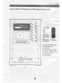
Rueckansicht
(
CD / MP3 Player mit USBJntertace
)
A
LCD Anzeige
B
PLAY/PAUSE
D
STOP
ID
SKIP
E
EJECT
ll
CD
Auswahl
G
USBAuswahl
H
Ordner SKIP
trtR
tr USB Eingang
E POWER/VOL.
1. MIC
IN
(BALANCE/UNBALANCE)
2. WRlKanalwahl
3. Wr2 Kanalwahl
4.AUX IN
5AUX OUT
6.MASTERVOLUME
T.SICHERUNG
E.POWER
(ON
/ OFF)
9.MtC
1O.WR1 VOLUME
11.WR2VOLUME
l2.AUXVOLUME
13.TAPE VOLUME
14.BASS
15.TREBLE
16.AC Eingang JACK / SICHERUNG
1 T.Batteriezustandsanzeige
1A.DC24-32V ETNGANG
19.SPK
OUT
20.sPK OUT
(GESCHALTET)
n
E
=
T
tr
CO
player
Fembedienung.
/-\o
itr)
o\-,/
o.
E
':q-
E.iÜ
€
E9
s(o)
'd
ZC)
n€
E]
s.Ö
@rö
Co"
Erö
4ol
.ö
rya
EA
b:r
E IB EE!
"
E@@
Fig l.

Adventure
800 mit
CD / Mp3
Player
mit llsBlnterface
&
Gasseffe
n Deck
LCDAnzeige
PLAY/PAUSE
STOP
SKIP
E,|ECT
CDAswahl
USB Ausvyahl
Ordner
SKIP
IR
USB Eingang
POWERA/OL.
-
E
-
E
-
CD
player
Fembedienung.
2l.CASSETTEN
ABDECKUNG
22.AUFMHMETASTE
23.PI.AY
TASTE
24.SCHN
ELL
R{CKSPUL
TASTE
25.
SCHNELL
VORSPUL
TASTE
26.STOP/EJECT
TASTE
27.PAUSE
TASTE
fr
Lrrl
,ffi\E
IE E!A
q@P"
s
@o

Adve
ntu
re
Passrv
La utsp
rech
e r
IE

Stromzufuhr
und Batterie Handhabung
Die
Stromzuf
uhr des Adventure 800
Systems besteht aus zwei 12V
I
4.5
AH
Akkus
dle in
dem System integriert sind
(Lead
Acid Typ, ohne Memory Effekt
!).
Kenntnisse
mit dem
Umgang von Akkus sind zwingend erforderlich
um
eine
einwandfreie
Bedienung dieses
portablen
Soundsystems zu
gewaerleisten
und
um Störungen des
Systems zu
vermeiden.
Nach
dem erstmaligem Auspacken
derAdventure,
bitten
wir Sie
dieAkkus vor
der
ersten Benutzung
mind.
'1
0 Stunden zu laden. Dies
ist eine sehr wichtige
Maßnahme
um eine lange Lebenserwartung
derAkkus
gewährleisten
zu können.
Ein nicht
beachten
dieses Hinweises kann zu fehlerhaften Funktionen
oder zu einer
kürzeren
Lebenszeit
derAkkus führen.
VorAuslieferung
wurden die
Akkus ab Werk vollstaendig
geladen.
Da
lhre
Adventure
jedoch
u. U.
Laenge
re Zeitgelagert wurde, koennen
die Akkus
teilentladen
sein. Es ist daher dringend
yu
empfehlen, die Akkus vor der
Inbetriebnahme
noch einmal vollstaendig
aufzuladen.
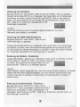
Zum Aufladen der
Batterien stecken
Sie
das beigefuegte
Netzkabel in die
Netybuchse
16 und verbinden
es dann mit einer 230V Schutzkonmtakt
Steckdose
Der Ladevorgang
startet
automatisch und die
Batterlezustandsanzeige
17 beginnt
zu
blinken. Ein
permanent
grünes
leuchten
bedeutet,
dass die Adventure vollständig
aufgeladen ist. lhre Adventure
kann nun
in Betrieb
genommen
werden.
Wenn
die
Batteriezustandsanzeige
Rot leuchtet
bedeutet dies, dass derAkku
Zustand
zu
gering
ist und die Adventure
aufgeladen
werden
muss. Für
den Fall,
dass
Sie das System dringend
benötigen bevor der Ladeprozess abgschlossen
ist,
ist
dies nur möglich wenn
derAkku mind.5 Minuten vorgeladen wurde,
dann kann
das
System beim Ladevorgang
gleichzeitig
benutzt und aufgeladen werden.
tp
Page is loading ...
Page is loading ...
Page is loading ...
Page is loading ...
Page is loading ...
Page is loading ...
Page is loading ...
Page is loading ...
Page is loading ...
Page is loading ...
Page is loading ...
Page is loading ...
-
 1
1
-
 2
2
-
 3
3
-
 4
4
-
 5
5
-
 6
6
-
 7
7
-
 8
8
-
 9
9
-
 10
10
-
 11
11
-
 12
12
-
 13
13
-
 14
14
-
 15
15
-
 16
16
-
 17
17
-
 18
18
-
 19
19
-
 20
20
-
 21
21
-
 22
22
-
 23
23
-
 24
24
-
 25
25
-
 26
26
-
 27
27
-
 28
28
-
 29
29
-
 30
30
-
 31
31
-
 32
32


Chiayo Adventure 800 SQ-5016 Operating instructions
- Type
- Operating instructions
- This manual is also suitable for
Ask a question and I''ll find the answer in the document
Finding information in a document is now easier with AI
Related papers
Other documents
-
Emerson EZL Series Pressure Reducing Regulator for Low Pressure Applications Important information
-
 Sollae Systems EZL-60R User manual
-
Sanyo ABC-VW24A - Air Washer Plus™ User manual
-
Sanyo ABC-VW24A User manual
-
 Sollae Systems EZL-400S User manual
-
 Sollae Systems EZL-410 User manual
-
TAG PA-223 User manual
-
-
 BTX 2.4 GHz Programming Manual
-
 Sollae Systems EZL-70 User manual


