
TRIPOD
MAST MOUNT

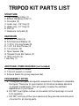
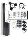
TRIPOD KIT PARTS LIST
STRUCTURE
1. Top Clamping Collar (1)
2. Bottom Clamping Collar (1)
3. Cross Bar (3)
4. Lower Leg – 26” long (3)
5. Upper Leg – 61” long (3)
6. Foot (3)
7. Neoprene foot pads (3)
HARDWARE
A. 5/16 X 1-1/4 Bolt (2)
B. 5/16 Stainless Washer (2)
C. 1/4 X 2-1/4 Long Screw (9)
D. 1/4 X 3/4 Short Screw (3)
E. 1/4 Locknut (12)
F. Nylon Spacer (36)
G. Shaped Cross Bar Spacer (3)
H. Wire Lock Pin (3)
I. Hex Key (1)
ADDITIONAL ITEMS REQUIRED (not included)
1. 1/2 inch wrench or socket
2. 7/16 inch wrench or socket
3. Silicone Sealer for gluing neoprene feet
PREASSEMBLY NOTES
a. Throughout this guide are specific sequences of hardware to assemble
the tripod. These are for good reason to minimize hardware abrasion
on powder coated parts. This will greatly increase the aesthetic
appearance of your tripod!
b. DO NOT over tighten screws as movement of the tripod legs is crucial
to its operation.
c. DO NOT omit any of the nylon spacers as they provide a smooth point
of contact for all moving parts.


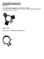
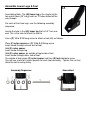
Assemble Mast Clamping Collars
Upper Collar:
Place (B) 5/16 stainless washer onto (A) 5/16 x 1-1/4 Bolt.
Thread (A) 5/16 x 1-1/4 Bolt through clamping tabs on (#1) Top Clamping Collar then
turn two times using a ½” wrench.
Bottom Collar:
Repeat process for (#2) Bottom Clamping Collar.

Assemble Lower Legs & Feet
Assembling Note: The (#4) lower leg is the shorter of the
two metal tubes (26” long) and has 12 holes drilled all the
way through.
For each of the three legs, use the following assembly
sequence:
Locate the hole in the (#4) lower leg that is 0.5” from one
end. This is the hole to attach the foot to.
Use a (C) 1/4 x 2-1/4 long screw to attach a foot (#6) as follows:
Place (F) nylon spacer on (C) 1/4 x 2-1/4 long screw.
Insert screw through exterior wall of foot.
Add (F) nylon spacer.
Insert screw through leg.
Add (F) nylon spacer on outside of leg/inside of foot.
Insert screw through other side of foot.
On outside of foot, place (F) nylon spacer and then (E) lock nut onto screw.
You will use a total of 4 nylon spacers for each foot assembly. Tighten the nut; but
allow the foot to swing freely.
Assembly Sequence: Assembled

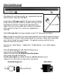
Assemble Legs
Note: The larger of the two metal tubes is the upper leg of the assembly. The upper
leg will have a hole that is 25.125 inches from one end of the leg. This end is the
“bottom” of the upper leg portion.
The (#4) lower leg (smaller diameter tube) is inserted into the
“bottom” of the (#5) upper leg.
Insert (#4) lower leg into (#5) upper leg and secure with (H)
Wire Lock Pin through the lowest bottom hole.
Repeat process for two remaining legs.
Attach legs to top collar
Note: Make sure all three bolt heads are on the
right hand side of collar shoulders.
Attach (#5) upper legs to (#1) top collar. This is
best accomplished by having the tripod legs in a
horizontal position laying down.
Attach each leg with (C) 1/4 x 2-1/4 long screw in the
following manner:
Place (F) nylon spacer on (C) 1/4 x 2-1/4 long screw.
Insert screw through right side of one of the (#1) top collar attachment points, through
the (#5) upper leg, and through the other side of (#1) top collar leg attachment point.
Add (F) nylon spacer then (E) lock nut. (You will only use two nylon spacers in this
portion of assembly.)
Assembly Sequence: Assembled

Attach Cross Bars to Legs
Stand top collar and leg assembly up – spread each leg, out
from the center, about one foot apart.
Locate hole in (#5) upper leg 25.125 inches from the bottom
of leg (it’s the only hole toward the middle of the leg, but the
orientation of this hole is crucial to the operation of the
tripod.) Be sure that the middle hole is closer to the bottom
of the leg than the top. This is where the support bar is
attached.
Attach (#3) cross bar to the leg assembly using 2-1/4” long screw as follows:
Note: Facing the assembly, the screw head should be on the right of leg (same side as
shaped spacer). If screw is tight, going through the cross bar, simply use the provided
hex L-Key to thread the screw through it. The powder coating is quite thick and
tolerance levels are very close.
Screw head - Nylon Spacer – Support Bar - Shaped Spacer - Leg – Nylon spacer-
Lock nut
Place (F) nylon spacer on (C) 1/4 x 2-1/4 long screw.
Insert screw through (#3) cross bar.
Add the flat side of the (G) Shaped Cross Bar Spacer.
Insert screw assembly through leg.
Add (F) nylon spacer on outside of leg then (E) lock nut onto screw.
Tighten the nut; but allow the cross bar to swing freely.
Assembly Sequence: Assembled

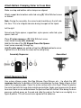
Attach Bottom Clamping Collar to Cross Bars
Make sure top and bottom collar clamps are aligned.
Attach support bar to bottom collar tab using (D) 1/4 x 3/4 short screw
as follows:
Note: Facing the assembly, the screw head should be on the left side
this time. This is to mitigate abrasion during transport of the tripod.
Left to right:
Screw head, Nylon spacer, support bar, nylon spacer, collar tab, nylon
spacer, lock nut
Place (F) nylon spacer on (D) 1/4 x 3/4 short screw.
Insert screw through (#3) cross bar.
Add the flat side of the (G) Shaped Cross Bar Spacer.
Insert screw assembly through leg.
Add (F) nylon spacer on outside of leg then (E) lock nut onto screw.
Tighten the nut; but allow the cross bar to swing freely.
Assembly Sequence: Assembled
Attach Neoprene Feet
Use a clear silicone sealer (like Dap Silicone, Dow Silicone, etc…) to attach the (#7)
neoprene feet onto the bottoms of the feet assembled on the legs. Apply silicone to one
side of the neoprene pads. Cover the entire surface with a thin layer. Place the pad on
the metal foot with the large hole matching orientation. Apply even pressure to the pads
to ensure there are no voids between the pad and foot left unfilled. After doing the even
pressure method, press on the pad and slide the pad on the foot ever-so-slightly in a
figure-8 pattern. This will ensure even spread of the adhesive.

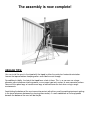
The assembly is now complete!
USEAGE TIPS:
You can install the mast in the tripod with the tripod in either the vertical or horizontal orientation.
Loosen the top and bottom clamping collars and slide the mast through.
For additional stability, the feet of the tripod have a hole in them. This is so you can use a large
diameter spike to hammer into the ground, use an auger type twist anchor, or even concrete anchors.
Some will also place bags of sand or even bags of concrete over the feet when using in rough
environments.
Avoid letting the bottom of the mast come into contact with dirt or sand (to avoid contaminants getting
in the close tolerances between the sleeving tube section). A small wood block of 2x4 or plywood
beneath the bottom of the mast will do the job.

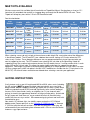
MAST KITS AVAILABLE
We have seven mast kits available that will work with our Tripod Mast Mount. Ranging from as short as 12.1
feet when fully extended, that could fit in a luggage bag, up through the 50 foot tall MK-8-HD mast. These
Tripods will accept any mast with a 2.5 inch OD Round base tube.
See the chart below:
Part
Number
Maximum
Usable
Length
Length
when
sleeved
Minimum
overlap of
tubes
Length
of
tubes
OD of
bottom tube
section
OD of
top tube
section
Number
of
Sections
Weight
MK-8-HD
50 feet
9 feet
5 inches
8.5 inches
93
inches
2.5 inches
1 inch
7
22.6 Lbs
MK-6-EXT
43.3 feet
7 feet
10 inches
8 inches
72
inches
2.5 inches
3/4 inch
8
18.9 Lbs
MK-6-HD
38 feet
7 feet
7 inches
8 inches
72
inches
2.5 inches
1 inch
7
17.8 Lbs
MK-4-EXT
28.5 feet
5 feet
8 inches
4.25 inches
46.5
inches
2.5 inches
3/4 inch
8
12.75 Lbs
MK-4-HD
25 feet
5 feet
6 inches
4.25 inches
46.5
inches
2.5 inches
1 inch
7
12 Lbs
MK-2-EXT
14 feet
3 feet
10 inches
3 inches
23.25
inches
2.5 inches
3/4 inch
8
7.2 Lbs
MK-2-HD
12.1 feet
3 feet
7 inches
3 inches
23.25
inches
2.5 inches
1 inch
7
6.75 Lbs
When selecting a mast, do not just look at the maximum usable height. Be sure to take note of the differences
in the different models. The HD and EXT have a bottom tube section starting at 2.5 inches where the STD
starts at only 2 inches. These diameter differences are very pronounced when trying to figure out what you
want to support by the mast. The STD models have a piece of 3/4 inch tube at the top making it ideal for
supporting things like a vertical wire antenna whereas the HD models have a 1 inch top section which is much
more stiff than the 3/4 inch tube. This allows for greater rigidity and allows for support of more robust
equipment. Tube length also makes a difference when deciding as a shorter piece of 3/4 inch tube is far more
stiff than a longer one (a 46.5 inch piece in the MK-4-EXT would be less flexible than the 72 inch piece in the
MK-6-EXT). All of these factors need to be considered when selecting a mast for your application.
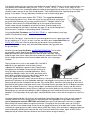
GUYING INSTRUCTIONS
A tall structure such as our full-length model MK-8 or MK-6 series masts (including
the HD versions) MUST be guyed and kept under control with guys even while
being erected. NOTE: Do NOT use metal guy cables with this mast system! Metal
cables are conductive and HEAVY and add significantly to the vertical loading of
the mast. Enlist three friends, family, or neighbors (or 4, if you choose 4 point
guying) to stand in the approximate locations of the guy anchor points, and to hold
the guy ropes and “feed them out” as you extend the mast, all the while being
certain that the mast stays vertical. We recommend guying at least two levels with
three direction guys.
Non-stretch, UV resistant, light, low visibility ropes such as the 1/8” OD black
double-weave Dacron rope such as the “Hexrope 4” (1000 foot rolls) or “Hexrope
3” (200 foot rolls) that we sell are ideal. If you are not proficient in knot tying, we
recommend that you seek tutoring from someone who is OR use a tension device
known as a guy rope tensioner.

Our specially made guy rings are tough, non-conductive, and UV-proof. Our guy rings are made in seven sizes
to fit perfectly on our different tubes (3/4 inch, 1 inch, 1.25 inch, 1.5 inch, 1.75 inch, 2 inch, and 2.25 inch).
Having these seven sizes should offer adequate choice of guying position for almost any use. These guy rings
slip on the tubes and rest on the Quik-Clamp beneath. They are drilled for either 3-point guying or 4-point
guying, as you prefer. The guy rope holes are counter-sunk to avoid cutting ropes.
Be sure to check out our part number: GUY-TEN-01. These guy line tensioners
make the guying process easy. Attach the ring on the guy tensioner to your ground
guy points (one tensioner per guy rope), pull back on the “T-Shaped” portion of the
tensioner, which loosens the three ball bearings on the interior of the tensioner.
Feed the rope through the opposite end of the tensioner. Grab the body of the
tensioner and begin to take up the slack from the rope. Pull to the desired tightness.
Each tensioner is rated for a safe working load of 110 pounds!
Using the Guy Line Tensioners (our P/N GUY-TEN-01) is a quick and easy way to guy a
mobile OR a permanent setup!
With the Guy Tensioners, if you are not using a mounting point that has a opening to hook
the guy tensioner’s “D” ring to / or even if you are, we offer a pear shaped Quick Link (our
P/N QL-NPS-1625) that is ideal to attach the guy tensioners to any attachment
point. This will make a strong, rock solid connection between your guy point and
the guy tensioner.
We also have designed Guy Stakes (our P/N GUY-STAKE-23). These stakes
are incredibly strong. Made of galvanized steel angle, these stakes can be
deployed numerous times and not bend like most all others out there. Being
made of angle steel, these stakes bite into an enormous amount of earth unlike
the thin auger type anchors which bend and bow under the stress of guying a
structure.
Guying shorter masts such as our models MK-4 and MK-6
depends on your application, and the item(s) being
supported. An adequately spaced, at least 2-point clamp
arrangement on the bottom section may be sufficient for
many light duty or partially-extended applications. When
clamping to fiberglass tubes with U-bolts, be careful not to
over-tighten to avoid crushing the tube. When in doubt, guy!
Err on the side of over-engineering, never under!
Even with guyed structures, always secure the base in a secure fashion where it cannot move. In semi-
permanent installations, be sure the bottom tube end is not plugged so that water can drain out. Water can
freeze and split the tube if allowed to accumulate. Guy anchor points should be strong enough to withstand a
great deal of pulling force, and away from the mast far enough that the guy ropes form a 45-degree or greater
angle with respect to the mast. If the guy anchor points are too close to the mast, the guys not only exert a
great deal of downward pressure on the mast, adding to the vertical load, but they have far less mechanical
advantage on the structure while doing their job of keeping your mast stable during severe environmental
conditions. Final adjustment of your guy ropes should be without excess slack, but not so tight as to “load” the
mast.
Leverage experienced with tall structures will make them impossible to hold at an angle, so again, keep the
structure vertical at all times during extension and retraction. Having people on all guy ropes to maintain
control (keeping the structure VERTICAL at all times) during raising or lowering the structure is a must.
When letting the structure down, be certain to maintain a firm grip on the inner tubes when you SLOWLY
release tension on the thumb clamp. Do not rely on the clamp tension only to let down each section. Gloves
(selected for a good grip on the tube surface) will be a BIG help. Always raise and lower in adequate lighting to
avoid accidentally extending the mast past the “stop” line you marked on the tubes. Again, ALWAYS have
adequate help on hand to maintain control of the structure when raising or lowering.

ONE YEAR LIMITED WARRANTY
Max-Gain Systems, Inc. (“MGS”) warrants its tripod mast mount to the original purchaser for a period of 30
days from the date of the original end-user purchase, that the tripod’s components and hardware shall be free
of defects in workmanship and materials, under normal use conditions and if installed, guyed, and maintained
in accordance with our provided instructions.
Exclusions and limitations
This warranty does not apply to conditions of faulty or improper installation, guying, or maintenance, or
alteration in any way that is not covered in the documentation for the product, or if the product is damaged by
acts of God, misuse, abuse, negligence, accident, normal wear and tear and deterioration, or lack of
responsible care, or by any other causes not related to defective materials or workmanship. This warranty does
not cover any antennas or other equipment mounted on or supported by our product.
Applicable law
This limited warranty is governed by the laws of the state of Georgia, USA.
Warranty claims
Requests for warranty adjustments shall be made in writing, (letter or email) to the address or email address shown on the
Max-Gain Systems, Inc. website.
MGS may, at our option, request return of defective parts. Any and all shipping to and from addresses outside the
contiguous 48 states in the USA shall be the exclusive responsibility of the purchaser. For customer addresses within the
contiguous 48 states in the USA, shipping of any damaged parts to MGS, should we (at our option) request their return,
shall be the responsibility of the purchaser. Shipping (via standard ground service) of replacement parts back to the
customer (within the 48 contiguous states of the USA) is covered under this limited warranty.
If a valid claim is received within the warranty period, the sole remedy of the original purchaser and Max-Gain Systems,
Inc.’s sole and exclusive liability shall be limited to, at Max-Gain Systems, Inc.’s sole discretion, replacement of the
defective component or replacement of the product, or refund of price paid for the product.
The warranties and remedies provided above are exclusive and in lieu of all other express or implied warranties including,
but not limited to, the implied warranties of merchantability or fitness for a particular purpose. Certain jurisdictions do not
allow the exclusion of implied warranties. If laws under such jurisdictions apply, then all express and implied warranties
are limited to the warranty period identified above. Unless provided herein, any statements or representations made by
any other person or firm are void. Except as provided in this written limited warranty and to the extent permitted by law,
neither Max-Gain Systems, Inc., or any affiliates shall be liable for any loss, inconvenience, or damage, including, but not
limited to direct, special, incidental, or consequential damages, resulting from the use or inability to use any Max-Gain
Systems, Inc. product, whether resulting from breach of warranty or any other legal theory.
Notwithstanding the foregoing, Max-Gain Systems, Inc.’s total liability for any and all claims under this limited warranty
shall not exceed the price paid for the product. These limitations on potential liabilities have been an essential condition in
setting the product price.
Thank you for your purchase!
Max-Gain Systems, Inc. Phone 770-973-6251
150 Dodd Street SE fax 815-461-7730
Marietta, GA 30060-2460 email: info@mgs4u.com
http://www.mgs4u.com
-
 1
1
-
 2
2
-
 3
3
-
 4
4
-
 5
5
-
 6
6
-
 7
7
-
 8
8
-
 9
9
-
 10
10
-
 11
11
-
 12
12


Ask a question and I''ll find the answer in the document
Finding information in a document is now easier with AI
Other documents
-
 Gap Titan User manual
-
Campbell Scientific CM106BK Owner's manual
-
-
-
 Will Burt AntennaMast AM2 User manual
-
-
-
 Tarheel Antennas MFJ-1793 User manual
-
 CUSHCRAFT A26B2-VPK User manual
-
 MFJ 1792 User manual


