• 6 •
2283+/-15 2250+/-15 1240+/-15 2683+/-20 2310 2309 1240
2783+/-15 2250+/-15 1240+/-15 2683+/-20 2810 2309 1240
3663+/-15 2250+/-15 1240+/-15 2683+/-20 3690 2309 1240
24 30 38 42 45 52 57 65 75 85
696 711 726 726 937 952 967 982 1150 1150
701 716 731 731 947 962 977 992 1165 1165
739 754 769 769 970 985 1000 1015 1225 1225
758 773 788 788 992 1007 1022 1037 1285 1285
744 759 774 774 980 995 1010 1025 1235 1235
763 778 793 793 1002 1017 1032 1047 1295 1295
-12,1 -12,1 -12,1 -12,1 -18,9 -18,9 -18,9 -18,9 -23,2 -23,2
-7 -7 -7 -7 -10,3 -10,3 -10,3 -10,3 -13,6 -13,6
-5,1 -5,1 -5,1 -5,1 -8,6 -8,6 -8,6 -8,6 -9,6 -9,6
0,9 0,9 0,9 0,9 1,8 1,8 1,8 1,8 2,5 2,5
11,2 11,2 11,2 11,2 20,8 20,8 20,8 20,8 30,3 30,3
22,8 22,8 22,8 22,8 30,9 30,9 30,9 30,9 39 39
3 3 3 3 4,5 4,5 4,5 4,5 6 6
14 14 14 14 21,5 21,5 21,5 21,5 31,2 31,2
20,8 20,8 20,8 20,8 26,7 26,7 26,7 26,7 26,7 26,7
25,4 25,4 25,4 25,4 32,5 32,5 32,5 32,5 32,5 32,5
37,4 37,4 37,4 37,4 45 45 45 45 62,3 62,3
49,6 49,6 49,6 49,6 67,5 67,5 67,5 67,5 92,9 92,9
36,2 36,2 36,2 36,2 54,9 54,9 54,9 54,9 86,4 86,4
20,9 20,9 20,9 20,9 28,4 28,4 28,4 28,4 35,9 35,9
65 65 65 65 70 70 70 70 87 87
139 139 139 139 156 156 156 156 195 195
272 272 272 272 295 295 295 295 440 440
218 218 218 218 241 241 241 241 358 358
174 174 174 174 209 209 209 209 239 239
BALTIC-IOM-0412-E / Installation manual
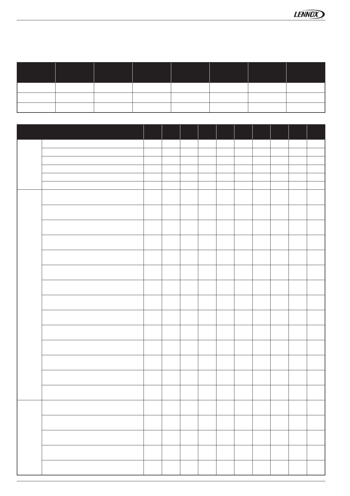
LIFTING THE UNITS
Machine dimensions and weights
Machine Length Width Height Width with
hood Transport
lenght Transport
Width Transport
Height
Cbox
Dbox
Ebox
Unit
Base weight (kg)
Cooling
HeatPump
Gas S
Gas H
Dual S
Dual H
Option weight (kg)
Horizontal return & supply
Horizontal return & vertical supply
Vertical return & horinzontal supply
Gravity exhaust damper
Power exhaust fan
F7 fi lter
F4 fi lter
Double skin
Electrical heater S
Electrical heater H
Electrical preheater S
Electrical preheater H
Hot water coil
Energy recovery coil
Accessorie weight (kg)
Non ajustable roofcurb
Ajustable roofcurb
Extraction curb vertical
Extraction curb horizontal
Multidirectional curb