Vixen X000055 Owner's manual

Category
Telescopes
Type
Owner's manual

This manual is also suitable for

Instruction Manual for
AP Equatorial Mount / AP-SM Equatorial Mount
/ AP Photo Guider
2
PREFACE
WARNING!
CAUTION
HANDLING and STORAGE
Thank you for your purchase of a Vixen product from the Vixen AP series of equatorial mounts and equatorial platform. This instruc-
tion manual is prepared in common with the AP series of the equatorial mounts including the AP-SM equatorial mount and AP Photo
Guider. You may occasionally find descriptions in the text not relevant to your model. The manual explains usage of the AP-SM mount
with STAR BOOK ONE mostly by way of example. Please be sure to read the instructions throughout to make you use the product
right and in safety.
This equipment has been tested and found to comply with the limits for a Class B digital device, pursuant of Par t 15 of the FCC rules.
This instruction manual will assist you in the safe and effective use of the AP Mount. Before using the mount, be sure to read the
safety precautions described below carefully.
Never look directly at the sun with your naked eyes or through your telescope and finder scope. Permanent and irreversible eye
damage may result.
Do not leave the optical tube uncapped in the daytime. Sunlight passing through the telescope or finder scope may cause a fire.
Do not use the product in a wet environment. This could damage the mount, result in electrical shock or a fire.
Do not attempt to disassemble or alter any part of the equipment that is not expressly described in this manual. This could
damage the mount, result in electrical shock, a fire or lead to an injury.
Keep small caps, plastic bags or plastic packing materials away from children. These may cause choking or suffocation.
Stop operating the product immediately and unplug the power cord if it emits smoke or a strange smell. This could result in fire
or electrical shock. Make sure to be safe and consult your local Vixen dealer or distributor in your country.
Do not allow liquids or foreign objects to enter the product. Unplug the power cord or switch the power off. This could result in
fire or electrical shock.
Do not damage, alter or place heavy item on the power cord. This could result in fire or electrical shock.
The product includes heavy items such as the counterweight and the mount body. Be sure to handle these units carefully. Be
careful not to drop the unit when handling. This may cause damage or lead to injury.
Be sure to ventilate air while cleaning with volatile cleaner or spray can cleaner to avoid poisoning.
Do not use the volatile cleaner or spray can cleaner in the vicinity to fire. This could lead to catching fire.
Do not operate the product with wet hands. Plugging in and out the power cord, electricity connectors and operating the electronic
parts with wet hands may cause damage to the equipment or resulting in electrical shock.
Do not use the product while traveling or walking, as injuries may arise from stumbling, falling or collision with objects.
Do not bundle the power cord and electricity wires during the operation. This may result in a short circuit and damage to the
surroundings.
Handle the power cord and electricity connectors properly. Do not pull the power cord by force when disconnecting. This may
damage the cord and connectors, resulting in fire or electrical shock.
Do not leave the product inside a car in bright sunshine, or in hot places. Keep any strong heat radiation sources away from the
product.
When cleaning, do not use solvent such as paint thinners. It may cause deterioration.
Do not use the product in a wet environment. This may cause the product to malfunction or result in fire or electrical shock.
For storage do not expose to direct sunlight and keep the product in a dry place.
Do not expose the product to rain, water drops, dirt or sand. Gently wipe the product with a damp cloth for cleaning.
SAFETY PRECAUTIONS
Legend
Warning
If misused, it can cause you a serious injury or death.
Caution
Misuse can cause injury or damage to you or other property.
Important You must complete all of the steps in this manual.
Direction You must completely execute the instructions in this manual.
3
TABLE OF CONTENTS Page
AP Mount
: Check the Package Contents --------------------------------- P4
: Name of Each Components ----------------------------------- P5
: Maunt Specifications ------------------------------------------- P5
AP Photo Guider
: Check the Package Contents --------------------------------- P6
: Name of Each Components ----------------------------------- P7
: Mount & Cotroller Specifications ----------------------------- P8
AP-SM Mount
: Check the Package Contest ----------------------------------- P9
: Name of Each Components ----------------------------------- P10
: Mount & Cotroller Specifications ----------------------------- P11
STAR BOOK ONE
: Components Guide --------------------------------------------- P14
: Polar Alignment Scope --------------------------------------- P34
: Polar Alignment in the Northern Hemisphere -------------- P36
: Polar Alignment in the Southern Hemisphere ------------- P41
: Mount Menu --------------------------------------------------- P47
Tracking Speed ------------------------------------------- P47
Tracking Direction ---------------------------------------- P48
Slewing Speed -------------------------------------------- P48
Backlash Compensation --------------------------------- P49
Setting for Autoguider ----------------------------------- P51
PEC -------------------------------------------------------- P52
: Display Menu -------------------------------------------------- P54
Contrast Adjustment ------------------------------------- P54
Brightness Adjustment ---------------------------------- P54
Backlight Adjustment ------------------------------------ P54
Red LED Light Adjustment ------------------------------ P55
: Other Functions ----------------------------------------------- P55
Field of View Orientation --------------------------------- P55
Reset ------------------------------------------------------ P56
AP Mount Composition Chart ------------------------------------ P56
Variations on the AP Mount --------------------------------------- P57
How to Change the Modules ------------------------------------- P58
: Changing the R.A. Motor Module for the Manual
Slow Motion Control Module. ------------------------------- P58
: Changing the Manual Slow Motion Control Module
for the DEC. Motor Module. --------------------------------- P60
: Changing the Maunal Slow Motion Control Module
for R.A Motor Module. --------------------------------------- P62
: Upgrading the AP Photo Guider to the AP Mount --------- P64
Replacing the Fuse ------------------------------------------------ P67
PREPARATION
SPECIFICATIONS
INITIAL SETTING AND BASIC OPERATION
APPLICATION
SAFETY PRECAUTIONS ---------------------------------------- P 2
TABLE OF CONTENTS ------------------------------------------- P 3
BEFORE USE ----------------------------------------------------- P 4
Assembling the Mount --------------------------------------------- P15
: Setting up the Tripod ------------------------------------------ P15
: Attaching the Counterweight -------------------------------- P18
: Attaching the Optical Tube Assembly ----------------------- P19
: Attaching the Dovetail Slide Bar (AP Photo Guider) -------- P20
: Balancing the Equatorial Mount ------------------------------ P21
: Connecting the STAR BOOK ONE --------------------------- P25
: About Power Supply ------------------------------------------- P26
: Tuning on the Power ------------------------------------------ P28
: Setting Language ---------------------------------------------- P28
: Moving the AP Mount
/ Moving the AP-SM Mount or Photo Guider ----------------- P29
: Changing the Slewing Speed --------------------------------- P29
: Changing Tension of the Friction Stop Motion ------------- P30
: Approximate Polar Aligning with the Finder Scope -------- P31
: Approximate Polar Aligning with the Polar Meter ---------- P33
Dimensions --------------------------------------------------------- P68
4
Check the Package Contents
The AP equatorial mount contains the items listed below. Check if all the items are included.
Package consisting of:
What is an Equatorial Mount?
Basic Motion of the AP Equatorial Mount
The AP equatorial mount moves and stops with friction in the right ascension (R.A) and declination (DEC). Slew the telescope by
hand to change the telescope’s direction. The AP-SM mount comes equipped with a drive motor on the R.A a xis and a manual slow
motion control knob on the DEC axis.
The equatorial mount will achieve smooth movements if each of the rotational axes on the mount is balanced correctly.
An unbalanced equatorial mount may cause vibration and can result in slipping of the friction stop mechanism. Make sure that your
telescope is well balanced af ter your accessories have been installed.
Be careful not to bang any par t of the mount against other objects. This could damage the gears and bearings.
In the northern hemisphere, stars appear to turn around the polar star (the nor th celestial pole) making approximately one rotation per day.
This is called diurnal motion and occurs because the ear th turns on its own axis once a day. The equatorial mount is a platform which i s
designed to rotatre parallel to ear th’s rotational a xis.
Basics of Equatorial Mounts
Note :
The contents of your AP mount package may differ when you
purchase it as a complete AP telescope package.
Counterweight Bar 1
AP Equatorial Mount (Main body) 1
Vanity Ring for Counterweight Bar 1
Slow Motion Control Knob 2
Allen Wrench of 3mm on a side 1
Counterweight 1.0kg 1
Allen Wrench of 4mm on a side 1
AP Mount Instruction Manual (This book) 1
BEFORE USE
5
BEFORE USE
Name of Each Component AP Mount
Safety Screw
R.A Axis (Polar Axis)
Polar Scope Window
Declination Body Cover
Vanity Ring for Counterweight Bar
R.A Manual Slow Motion Control Knob
Counterweight Bar
Counterweight Lock Knob
Counterweight 1.0Kg
Counterweight
Safety Screw
DEC Axis
Dovetail Plate Lock Screw
Mount Head
DEC Manual Slow Motion Control Knob
Accessory Shoe
Polar Axis Cap (for Polar Scope)
Installing space for Polar
Alignment Scope PF-L (inside)
Polar Axis Body
Altitude Adjustment Bolt
Azimuth Adjustment Knobs
Declination Body Cover
Battery Compartments*
Fuse*
* Utilized as a power supply when the R.A motor
module is attached.
Mount Specifications
Mount AP equatorial mount
Slow Motion Control
R.A: Wheel and worm gears full circle micro movement
DEC: Wheel and worm gears full circle micro movement
Quick Slewing Motion Friction stop motion (adjustable)
Wheel Gear R.A: 73.5mm in diameter, 144-tooth wheel gear / DEC:58.4mm in diameter, 144-tooth wheel gear
Worm Gear R.A :11.0mm in diameter, Brass / DEC:9.8mm in diameter, Brass
R.A Axis 59mm in diameter, Aluminum alloy, with friction stop mechanism
DEC Axis 59mm in diameter, Aluminum alloy, with friction stop mechanism
Number of Bearings 7 pieces
Counterweight Bar
20mm diameter, Steel
Polar Alignment Scope Optional
Azimuth Adjustment
Fine adjustment range: +/- 6.5 degrees, 1.4 degrees per rotation, Twin adjustment screws with knobs
Altitude Adjustment Latitude adjustment range: 0 degree to 65 degrees, Tangent screw with handle, 1.9 degrees per rotation
Maximum Loading Weight 6kg (13.2lbs)(150kg • cm torque load) at a point of 25cm from the fulcrum
Fuse 125V 1A Class B (PSE standard), 6mm dia x 30mm long
Dimensions 263 x 302 x 96mm (10.3” x 11” x 3.7”)
Weight 3.6kg (8 lbs) without counterweight
Counterweight 1.0kg (2.2 lbs)
Optional Accessories R.A motor module and STAR BOOK ONE Set, DEC motor module, APP-TL130 tripod, Polar alignment
Weight scope PF-L, Polar Meter
The specifications are subject to change without notice.
6
Check the Package Contents
The AP Photo Guider package contains the items listed below. Check if all the items are included.
BEFORE USE
Package consisting of:
Dovetail Slide Bar PG 1
AP Photo Guider Equatorial Platform 1
STAR BOOK ONE Controller 1
Strap for STAR BOOK ONE 1
Allen Wrench of 5mm on a side 1
Allen Wrench of 3mm on a side 1
STAR BOOK Cable (for SBT) 1
APP-TL130 Tripod 1
Allen Wrench of 4mm on a side 1
AP Photo Guider Instruction Manual (This book) 1
Note 1: Power supply is not included.
Note 2: Use a commercially available USB external power supply.
For AP Photo Guider with Single-axis drive unit (Standard): USB external battery of at least 0.5 ampere is required (applicable to USB
Micro-B connector).
For AP Photo Guider with Dual-axis drive unit (Optional): USB external battery of at least 1.0 ampere is required (in conformity to DCP
and applicable to USB Micro-B connector).
The DCP (Dedicated Charging Por t) is a regulation of USB external power supply which is stipulated in USB Battery Charging Specifi-
cation, Rev 1.1. It is used for USB batteries and USB AC Adapters.
7
AP Photo Guider
BEFORE USE
Name of Each Component AP Photo Guider
Safety Screw
R.A Axis (Polar Axis)
Dovetail Plate Lock Screw
1/4” Camera Mounting Screw (4 points)
Dovetail Slide Bar PG
Azimuth Adjustment Knobs
AP Mount Head Unit
R.A Motor Module
R.A. Clamp Lever
Polar Axis Cap (for Polar Scope)
Polar Alignment Scope PF-L (Inside)
Polar Axis Body
Altitude Adjustment Bolt
External Power Supply Port
(USB Micro-B : 5V)
Controller Cable Connecting Port
APP-TL130 Tripod
Power Switch
Leg Brace
Ferrule
Center Column
Leg Brace Lock Screw
Extension Lock Lever
Polar Alignment Scope PF-L
Equatorial Platform
Tripod
Polar Alignment Scope
Power Supply
8
BEFORE USE
Mount Specifications AP Photo Guider
Controller Specifications
Mount AP Photo Guider mount
Slow Motion Control
R.A: Wheel and worm gears full circle micro movement
Quick Slewing Motion Friction stop motion (adjustable)
Wheel Gear R.A: 73.5mm in diameter, 144-tooth wheel gear
Worm Gear R.A :11.0mm in diameter, Brass
R.A Axis 59mm in diameter, Aluminum alloy, with friction stop mechanism
Number of Bearings 4 pieces
Polar Alignment Scope
6x20mm (Field of view: 8 degrees), Self-light-off dark field illuminator (Brightness adjustable), Setting accuracy: 3
arc minutes or less, Reticle with scales for pointing 3 stars, Battery: CR2032
Azimuth Adjustment
Fine adjustment range: +/- 6.5 degrees, 1.4 degrees per rotation, Twin adjustment screws with knobs
Altitude Adjustment Latitude adjustment range: 0 degree to 65 degrees, Tangent screw with handle, 1.9 degrees per rotation
Motor Drive
Pulse (Stepping) Motor
Tracking High precision tracking with STAR BOOK ONE controller
Maximum Loading Weight 6kg (13.2 lbs) (150kg • cm torque load) at a point of 25cm from the fulcrum
Controller Cable Connecting Port
D-SUB 9PIN male plug
Power Supply Port USB Micro-B (DC4.4 to 5.26V)
Power Supply USB External battery pack (Not sold by Vixen)
Working Duration with
Batteries
About 4 hours (at 20 degree C, with Alkaline batteries, 6kg loading weight ), 2.5 hours if the DEC motor module is used
together.
Electricity Consumption DC5V • 0.2 ~ 0.5A (1.0 ~ 2.5W) , 0.3 ~ 1.0A (1.5 ~ 5.0W) if the DEC motor module is used together.
Dimensions 222 x 221x 96mm (8.7” x 8.7” x 3.7”)
Weight 2.4kg (5.3 lbs) (5.4kg (12 lbs) complete with tripod)
Optional Accessories Supplementary Counterweight Bar, Counterweight 1.0kg, Polar Meter
Controller STAR BOOK ONE
CPU
32-bit CISC Processor 40MHz RX210
LCD Screen 2-line 8-chracter STN with backlight
Autoguider Port 6-pole 6-wired modular jack (for external autoguider)
Controller Cable Port D-SUB 9PIN male plug
Power Supply Supplied from the mount side
Operating Temperature Between 0 degree C and 40 degree C (104 F)
Dimensions 137 x 65 x 21mm (5.4” x 2.5” x 1”)
Weight
110g (4 oz) (without cable)
Menus and Major
Functions
Sidereal tracking rate (variable from 0.1X to 10X by step), Solar tracking, Lunar tracking and Kings rates, Backlash
compensation, PEC, External autoguider connection, Adjustable LED backlight, Red LED Light
The specifications are subject to change without notice.
9
BEFORE USE
Check the Package Contents AP-SM Mount
The AP-SM equatorial mount package contains the items listed below. Check if all the items are included.
Package consisting of:
Power Supply to AP-SM Mount:
Power Supply to AP-SM Mount plus DEC Motor Module:
AP Counterweight Bar 1
AP-SM Equatorial Mount (Main body) 1
Vanity Ring for Counterweight Bar 1
Slow Motion Control Knob 1
STAR BOOK Cable (for SBT) 1
Allen Wrench of 4mm on a side 1
AP-SM Mount Instruction Manual (This book) 1
Counterweight 1.0kg 1
STAR BOOK ONE Controller 1
Strap for STAR BOOK ONE 1
Allen Wrench of 4mm on a side 1
Note 1: The contents of your AP-SM mount package may differ when you purchase it as a complete AP-SM telescope package.
Note 2: The AP-SM packages do not contain an adapter for power supply. Use 4 x AA batteries (not included) or a commercially available USB external
battery with USB Micro-B adapter.
The USB external power supply battery of at least 0.5 ampere is required for operation. USB Micro-B adapter is needed.
The USB external power supply battery of at least 1.0 ampere is required for operation. USB Micro-B adapter is needed.
If the power supply is not sufficient, the DEC motor will stop along with a blinking message “Y motor stop”.
The USB external power supply battery in conformity to DCP (Dedicated Charging Por t) of USB Battery Charging Specification, Rev
1.1 is required.
10
BEFORE USE
Name of Each Component AP-SM Mount
Safety Screw
R.A Axis (Polar Axis)
Polar Scope Window
Declination Body Cover
Vanity Ring for Counterweight Bar
R.A Motor
Counterweight Bar
Counterweight Lock Knob
Counterweight 1.0Kg
Counterweight
Safety Screw
External Power Supply Port
(USB Micro-B: 5V)
Controller Cable
Connecting Port
Power Switch
Battery Compartments
Fuse
Tripod Leg
Leg Brace
Ferrule
DEC Axis
Dovetail Plate Lock Screw
Mount Head
DEC Manual Slow Motion Control Knob
Accessory Shoe
Polar Axis Cap (for Polar Scope)
Polar Alignment Scope PF-L
(Inside)
Polar Axis Body
Altitude Adjustment Bolt
Azimuth Adjustment Knobs
Center Column
Leg Brace
Lock Screw
Extension
Lock Lever
The AP-SM Mount Package with A80Mf Optical Tube and
APP-TL130 Tripod are shown as an example.
11
BEFORE USE
Mount Specifications AP-SM Mount
Controller Specifications
Mount AP-SM equatorial mount
Slow Motion Control
R.A: Wheel and worm gears full circle micro movement
DEC: Wheel and worm gears full circle micro movement
Quick Slewing Motion Friction stop motion (adjustable)
Wheel Gear
R.A: 73.5mm in diameter, 144-tooth wheel gear
DEC:58.4mm in diameter, 144-tooth wheel gear
Worm Gear
R.A :11.0mm in diameter, Brass
DEC:9.8mm in diameter, Brass
R.A Axis 59mm in diameter, Aluminum alloy, with friction stop mechanism
DEC Axis 59mm in diameter, Aluminum alloy, with friction stop mechanism
Number of Bearings 7 pieces
Counterweight Bar
20mm (8”) diameter, Steel
Polar Alignment Scope Optional
Azimuth Adjustment
Fine adjustment range: +/- 6.5 degrees, 1.4 degrees per rotation, Twin adjustment screws with knobs
Altitude Adjustment Latitude adjustment range: 0 degree to 65 degrees, Tangent screw with handle, 1.9 degrees per rotation
Motor Drive Pulse (Stepping) Motor
Tracking High precision tracking with STAR BOOK ONE controller
Maximum Loading Weight
6kg (13.2 lbs) (150kg • cm torque load) at a point of 25cm from the fulcrum
Controller Cable Connecting Port
D-SUB 9PIN male plug
Power Supply Port USB Micro-B (DC4.4 to 5.26V)
Power Supply 4 x AA batteries (Alkaline or Ni-MH, Ni-Cd rechargeable batteries), External USB battery pack (Not sold by Vixen)
Working Duration with About 4 hours (at 20 degree C, with Alkaline batteries, 6kg loading weight ), 2.5 hours if the
Batteries DEC motor module is used together.
Electricity Consumption
DC5V • 0.2 ~ 0.5A (1.0 ~ 2.5W) , 0.3 ~1.0A (1.5 ~ 5.0W) if the DEC motor module is used together.
Fuse
125V 1A Class B (PSE standard), 6mm dia x 30mm long
Dimensions
274 x 310 x 96mm (11” x 12” x 3.7”)
Weight
3.9kg (8.5 lbs) without counterweight
Counterweight
1.0kg (2.2 lbs)
Optional Accessories
DEC motor module, APP-TL130 tripod, PG mount head unit, Polar alignment scope PF-L, Polar Meter
Controller STAR BOOK ONE
CPU 32-bit CISC Processor 40MHz RX210
LCD Screen 2-line 8-chracter STN with backlight
Autoguider Port 6-pole 6-wired modular jack (for external autoguider)
Controller Cable Port D-SUB 9PIN male plug
Power Supply Supplied from the mount side
Operating Temperature Between 0 degree C and 40 degree C (104 F)
Dimensions 137 x 65 x 21mm (5.4” x 2.5” x 1”)
Weight
110g (4 oz) (without cable)
Menus and Major Sidereal tracking rate (variable from 0.1X to 10X by step), Solar tracking, Lunar tracking and Kings rates,
Functions
Backlash compensation, PEC, External autoguider connection, Adjustable LED backlight, Red LED Light
The specifications are subject to change without notice.
12
-
BEFORE USE
Mount Specifications
Mount Head
Counterweight Bar
Right Ascension (R.A)
Declination (DEC)
The mounting block is designed to attach an optical tube with dovetail
tube plate (or dovetsail slide bar). The optical tube is firmly fixed with
both the lock screw with large grab knob and safety screw. This allows
quick set up and removal of the optical tube.
The optical tube mounted on the
equatorial mount has to be balan-
ced with a counterweight to use the
equatorial mount properly.
If the AP mount is set to be aligned with one rotational axis parallel to the
Earth’s axis, th e motion of R.A will follow th e motion of stars.
If the AP mount is set to be aligned with one rotational axis parallel to
the Earth’s axis, the motion of DEC will be angled to the motion of the
R.A.
Mount head
Dovetail-plate tube plate
Safety screw
Lock screw
Counterweights
Counterweights
Counterweight bar
Counterweight bar
Optical Tube
North
DEC axis
Polar axis
M
o
v
e
s
i
n
t
h
e
R
.
A
.
d
i
r
e
c
t
i
o
n
M
o
v
e
s
i
n
t
h
e
D
E
C
d
i
r
e
c
t
i
o
n
13
-
BEFORE USE
Friction Stop Mechanism
Altitude Adjustment Bolt
Azimuth Adjustment Knobs
Accessory Shoe
Power Supply Port
This is used for polar alignment during your set up for observation.
It is used to adjust the elevation of the polar axis to be parallel to
the Ear th’s a xis.
This is used for polar alignment during your set up for observation.
Adjust the direction of the polar a xis to be parallel to the Ear th’s
axis. Unfastening one side of the azimuth adjustment knob will
allow fastening the knob on the other side.
Attach an optional Polar Meter sold separately. It will allow you to
approximately align the AP mount to the Nor th Pole, if Polaris is not
seen from your observing site in the nor thern hemisphere.
The AP-SM mount runs on self-contained four (4) AA –size batteries,
or a USB external battery. The USB external battey with USB micro-
B adapter will be needed for long observing sessions.
The AP mount employs a friction stop mechanism which allows you
to move the optical tube by hand so that you can quickly point it at
your target celestial object The optical tube moves as you guide it by
hand and stops as you release.
Polar axis
North
DEC axis
Altitude adjustment
bolt
Azimuth
adjustment knob
Azimuth adjustment
bolt
Accessory shoe Polar Meter (optional)
USB micro-B adapter
14
Star
N x999
Patent Pending DC12V Max.0.5A
BEFORE USE
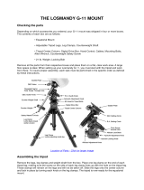
STAR BOOK ONE Components Guide
Note: Usage of the STAR BOOK ONE is described as operating Instructions for the AP-SM Mount here.
(11) Autoguider Port (12) Mount Connecting Port
(1) Mount button
LCD Monitor
(3) Direction Keys
(2) Display button
(4) RA Reverse button
(6) Plus and Minus buttons
(5) DEC Reverse button
(8) LED Light button
(10) Eyelet
(7) LED Light button
(10)
(1) Mount button
Set up menus for the mount such as tracking mode
and backlash compensation. Pressing the Mount
button turns up the brightness of the button itself and
allows you to change the settings with the direction
keys. Press the Mount button again to leave the menu
and the brightness dims. The new setting is saved as
you enter the new value. (Your recorded PEC data are
for temporary use and not saved when you turn off
the mount.)
(2) Display button
Set up menus for the controller such as language and
backlight adjustments. Pressing the Display button
turns up the brightness of the button itself and allows
you to change the settings with the direction keys.
Press the Display button again to leave the menu and
the brightness dims. The new setting is saved as you
enter the new value.
(3) Direction Keys
You can move your telescope in the RA and DEC directions
with these keys. Pressing any of the four direction keys will
accelerate the motor speed toward the maximum value you
selected. (The DEC direction keys will be inoperative if the
single-axis drive is applied to the AP-SM mount.) Then, that
speed is maintained while the key is being pressed. The motor
speed is decelerated lf you stop pressing the key. The Direction
keys function as menu selection buttons to change the settings
while the Mount button or Display button is selected and lit.
(4) RA Reverse button
The tracking direction of the RA can be reversed to have
the orientation of your eyepiece’s field of view change to the
opposite direction. Pressing the RA Reverse button turns up
the brightness of the button itself and the button will function.
Pressing the button again will change the orientation of the
telescope to the original direction, and will turn down the
brightness of the button as you leave the menu.
(5) DEC Reverse button
The tracking direction of the DEC can be reversed to have the
orientation of your eyepiece’s field of view change to the opposite
direction. (The DEC reverse button will be inoperative if the single-
axis drive is installed on he AP-SM mount.) Pressing the DEC
Reverse button turns up the brightness of the button itself and
the button will function. Pressing the button again will change the
orientation of the telescope to the original direction, and will turn
down the brightness of the button as you leave the menu.
(11) Autoguider Port
Compatible with the SBIG autoguider’ s connection port. Designed for 6-pole
6-wired modular jack.
(12) Mount Connecting Port
A connecting por t to connect between the AP mount and the STAR BOOK ONE.
Designed for D-SUB9PIN.
(6) Plus and Minus buttons
Use these but tons to set up the maximum slewing
speed of the telescope. The Plus and Minus buttons
function as menu selection buttons to change settings
as long as the Mount button or Display button is
illuminated.
(7) LED Light button
There is a built-in red LED light on the back of the
STAR BOOK ONE. The red light is switched to ON or
OFF alternatively each time the button is pressed. The
red lightstays lit while you continue pressing the LED
light button and the light goes off as you release the
button.
(8) LED Light button
A 2 line (8 character each line) information screen with adjustable backlight.
(9) Red LED Light
The built-in red LED light on the back of the STAR BOOK ONE is useful to
keep your eyes acclimated to darkness at an observation site when you want
to avoid white light.
(10) Eyelet
T The eyelet hole is for a strap. The eyelets are provided on either side
of the controller.
15
PREPARATION
Assembling the Mount
Setting up the Tripod
Ferrule
Rubber
Extension lock lever
Level
Leg brace lock screw
Center column
Leg brace
Refer to the instruction manual of your telescope and accessory together with this manual when you attach the optical tube assembly to the mount.
The unit includes heavy items. Take care not to drop them when assembling as it could cause seriously damage the equipment or lead to injury.
Take care not to pinch your finger with moveable pieces when setting up.
1
Place the tripod on level ground to make the telescope stable
during observation.
2
Unfasten the extension lock lever on the tripod leg by pulling it
out so that the tripod leg can be adjusted. To keep better stability,
extend the upper section of the tripod legs first. Pull out the tripod
legs until each leg comes to your desired length.
3
Fasten the extension lock lever to hold the tripod leg securely in
place.
4
Loosen the lock screw on the leg brace and pull the tripod legs
apart until the leg brace is fully extended.
16
PREPARATION
Post
Post
Azimuth adjustment screw
Azimuth adjustment screws
Post
5
Attach the metal post on the t r ipod head. The metal post
is underneath the center column. Be sure to screw down
the metal post completely
6
Loosen the azimuth adjustment screws in advance by
turning the a zimuth adjus tment knobs on the mount base
so that a space is opened for the metal post between the
screws.
7
Position the mount so that the two azimuth adjustment
screws come above the metal post. Place the mount on
the tripod head so that the center projection on the bottom
of the mount fits the center hollow on the tripod head.
8
Holding the mount with one hand, raise the center column with the hand so that the
top of the column is fit the bottom of the mount. Turn the center column counter-
clockwise to screw the top of the column into the bottom of the mount until secure.
Center column
17
PREPARATION
9
Tighten the azimuth adjustmen t knobs on the moun t base
so that the two knobs are equally tightened.
10
Push down the leg brace until it clicks as to secure the
stability of the tripod. Tighten the leg brace lock screw
securely.
11
Repeat the above procedure when you change the height of the tripod.
12
Attach the Slow Motion Control Knobs
The slow motion control knob is at tached onto the worm screw by push fit. Place the
manual slow motion control knob on the tip of the worm screw shaft so that the flat portion
of the socket on the knob is joined with the flat por tions of the tip on the shaft. For the AP-
SM mount, at tach the the slow motion control knob to the DEC worm screw shaft only.
Flat portion of the shaft
Worm gear shaft
Flat portion of the socket
Slow motion control knob
Manual slow motion control module
Worm gear shaft
Azimuth adjustment screws
Leg brace
Lock screw
18
PREPARATION
Attaching the Counterweight
1
Screw the counterweight bar into the vanity ring until it is snug.
Then, turn it back by one roation.
2
Screw down the counterweight bar into the declination body
fully and tighten the vanity ring securely.
3
Remove the safety screw on the end of the counterweight bar.
4
Make sure that the counterweight bar is at the lowest position
and attach the count e rweigh t . Loosen the lock knob on the
counterweight and put through the counterweight so that the
lock knob is on the far side of the end of the counterweight
bar. At this stage the counterweight should be close to the end
of the counterweight bar to lower the center of the balance.
Tighten the lock knob.
5
Replace the safet y screw on the end of the counterweight bar
and tighten it.
Vanity ring for Counterweight bar
Counterweight bar
Counterweight bar
Declination body
Safety screw
Safety screw
Lock knob
Be sure to attach the counterweight before you install the optical tube assembly on the mount.
Note: Make sure that the lock knob is tightened firmly before you
release your hand from the counterweight.
19
×
PREPARATION
Attaching the Optical Tube Assembly
Safety screw
Safety screw
Back off
Dovetail tube plate
Dovetail Slide bar
Dovetail plate
lock screw
Dovetail plate
lock screw
1
Loosen both dovetail plate lock
screw and safety screw on the
mount head fully so that space
is available to insert the dovetail
tube plate.
2
Attach the telescope tube to the mount head so that the
dovetail tube plate fits securely into the sunken mount head.
Tighten the dovetail plate lock screw first onto the dovetail tube
plate centering notch until it is snug. Then, tighten the safety
screw securely.
The telerscope tube attaches to the AP mount via a dovetail tube plate.
The permissible loading weight of the mount is 6kg (13.2 lbs).
Tightening the dovetail plate lock screws with a gap between these
parts may cause the telescope tube to fall.
Caution: Take care not to drop the telescope tube as it could result in serious damage.
Note: Make sure that the dovetail tube plate is flat against the mount head.
20
-
PREPARATION
Attaching the Dovetail Slide Bar AP Photo Guider
Safety screw
Safety screw
Back off
Dovetail plate
lock screw
Dovetail plate
lock screw
Stopper
Stopper
Set screw
Set screw
Set screw
4mm Allen wrench
Tip of the lock screw
1
Loosen both the dovetail plate lock screw and safety screw on
the mount head fully so that space is available for the dovetail
slide bar.
2
Attach the dovetail slide bar to the mount head so that the
dovetail slide bar fits securely into the sunken mount head.
Orientate the dovetail slide bar as shown in the figure to pre-
vent the dovetail slide bar from falling. (The dovetail slide bar
has a stopper screw on one side of the dovetail rail.) Attach
the dovetail slide bar so that the tip of the dovetail plate lock
screws hits on another part of the dovetail rail with no stopper
screws.
3
First tighten the dovetail plate lock screw onto the dovetail
slide bar centering notch until it is snug. Then, securely tighten
the safety screw.
The mount head unit is attached onto the head of the polar axis body
aseembly with three set screws that are equally put on its side. The
set screws can be loosened with the 4mm Allen wrench to change
the position of the mount head to pint at your desired orientation.
About the orientation of the mount head unit
  • Page 1 1
  • Page 2 2
  • Page 3 3
  • Page 4 4
  • Page 5 5
  • Page 6 6
  • Page 7 7
  • Page 8 8
  • Page 9 9
  • Page 10 10
  • Page 11 11
  • Page 12 12
  • Page 13 13
  • Page 14 14
  • Page 15 15
  • Page 16 16
  • Page 17 17
  • Page 18 18
  • Page 19 19
  • Page 20 20
  • Page 21 21
  • Page 22 22
  • Page 23 23
  • Page 24 24
  • Page 25 25
  • Page 26 26
  • Page 27 27
  • Page 28 28
  • Page 29 29
  • Page 30 30
  • Page 31 31
  • Page 32 32
  • Page 33 33
  • Page 34 34
  • Page 35 35
  • Page 36 36
  • Page 37 37
  • Page 38 38
  • Page 39 39
  • Page 40 40
  • Page 41 41
  • Page 42 42
  • Page 43 43
  • Page 44 44
  • Page 45 45
  • Page 46 46
  • Page 47 47
  • Page 48 48
  • Page 49 49
  • Page 50 50
  • Page 51 51
  • Page 52 52
  • Page 53 53
  • Page 54 54
  • Page 55 55
  • Page 56 56
  • Page 57 57
  • Page 58 58
  • Page 59 59
  • Page 60 60
  • Page 61 61
  • Page 62 62
  • Page 63 63
  • Page 64 64
  • Page 65 65
  • Page 66 66
  • Page 67 67
  • Page 68 68
  • Page 69 69
  • Page 70 70
  • Page 71 71
  • Page 72 72

Vixen X000055 Owner's manual

Category
Telescopes
Type
Owner's manual
This manual is also suitable for

Ask a question and I''ll find the answer in the document

Finding information in a document is now easier with AI