Page is loading ...

613-001058 Rev. A
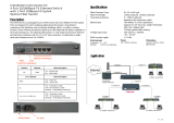
AT-9000/28
Managed Layer 2
GE ecoSwitch
Installation Guide

Copyright 2008 Allied Telesis, Inc.
All rights reserved. No part of this publication may be reproduced without prior written permission from Allied Telesis, Inc.
Allied Telesis and the Allied Telesis logo are trademarks of Allied Telesis, Incorporated. All other product names, company names, logos or
other designations mentioned herein are trademarks or registered trademarks of their respective owners.
Allied Telesis, Inc. reserves the right to make changes in specifications and other information contained in this document without prior
written notice. The information provided herein is subject to change without notice. In no event shall Allied Telesis, Inc.be liable for any
incidental, special, indirect, or consequential damages whatsoever, including but not limited to lost profits, arising out of or related to this
manual or the information contained herein, even if Allied Telesis, Inc. has been advised of, known, or should have known, the possibility of
such damages.

3
Electrical Safety and Emissions Standards
This product meets the following standards.
RFI Emissions FCC Class A, EN55022 Class A, VCCI Class A, C-TICK, CE
EMC (Immunity) EN55024, EN61000-3-2, EN61000-3-3
Electrical Safety EN60950-1 (TUV), UL 60950-1 (
C
UL
US
)
U.S. Federal Communications Commission
Radiated Energy
Note: This equipment has been tested and found to comply with the limits for a Class A digital device pursuant to Part 15
of FCC Rules. These limits are designed to provide reasonable protection against harmful interference when the
equipment is operated in a commercial environment. This equipment generates, uses, and can radiate radio frequency
energy and, if not installed and used in accordance with this instruction manual, may cause harmful interference to radio
communications. Operation of this equipment in a residential area is likely to cause harmful interference in which case
the user will be required to correct the interference at his own expense.
Note: Modifications or changes not expressly approved of by the manufacturer or the FCC, can void your right to operate
this equipment.
Industry Canada
This Class A digital apparatus complies with Canadian ICES-003.
Cet appareil numérique de la classe A est conforme à la norme NMB-003 du Canada.
Warning: In a domestic environment this product may cause radio interference in
which case the user may be required to take adequate measures.
Laser Safety EN60825

4
Translated Safety Statements
Important: The indicates that a translation of the safety statement is available in a PDF
document titled “Translated Safety Statements” (613-000990) posted on the Allied Telesis website at
www.alliedtelesis.com. This document is also included with the documentation CD that is shipped
with the product.

5
Contents
Contents ...............................................................................................................................................................................5
Preface ..................................................................................................................................................................................7
Safety Symbols Used in this Document..................................................................................................................................8
Where to Find Web-based Guides .........................................................................................................................................9
Contacting Allied Telesis ......................................................................................................................................................10
Online Support ..............................................................................................................................................................10
Email and Telephone Support .......................................................................................................................................10
Returning Products........................................................................................................................................................10
For Sales or Corporate Information...............................................................................................................................10
Warranty........................................................................................................................................................................10
Management Software Updates ....................................................................................................................................10
Chapter 1: Overview ..........................................................................................................................................................11
Switch Features....................................................................................................................................................................12
Front and Back Panels .........................................................................................................................................................13
Gigabit Ethernet Ports ..........................................................................................................................................................14
Twisted Pair Ports .........................................................................................................................................................14
Uplink Ports ...................................................................................................................................................................15
RS-232 Console Port ....................................................................................................................................................15
LEDs.....................................................................................................................................................................................16
System LEDs.................................................................................................................................................................16
RJ-45 Port LEDs & MODE Switch.................................................................................................................................17
SFP LEDs......................................................................................................................................................................19
ecoSwitch .............................................................................................................................................................................20
Ethernet Switching Basics ....................................................................................................................................................21
MAC Address Table ......................................................................................................................................................21
Duplex Mode .................................................................................................................................................................22
Auto
MDI/MDI-X............................................................................................................................................................................22
Store and Forward.........................................................................................................................................................22
Back Pressure and Flow Control.................................................................................................
..................................22
Chapter 2: Installing the Switch .......................................................................................................................................25
Reviewing Safety Precautions..............................................................................................................................................26
Selecting a Site.....................................................................................................................................................................28
Twisted Pair and Fiber Optic Cable Specifications...............................................................................................................29
Twisted Pair Cable Specifications .................................................................................................................................29
Optional Transceiver Cable Specifications....................................................................................................................29
Unpacking the Switch ...........................................................................................................................................................30
Installing the Switch in a Rack ..............................................................................................................................................31
Installing Optional Transceivers............................................................................................................................................33
Installing an SFP Transceiver .......................................................................................................................................33
Cabling the Twisted Pair or Fiber Optic Ports.......................................................................................................................35
Applying AC Power...............................................................................................................................................................36
Starting a Local Management Session.................................................................................................................................37
Warranty Registration...........................................................................................................................................................39

Contents
6
Chapter 3: Troubleshooting ..............................................................................................................................................41
Power LED is Off ..................................................................................................................................................................42
Twisted Pair Port Link LED is Off..........................................................................................................................................43
Fiber Optic Port Link LED is Off............................................................................................................................................44
Cannot Establish a Local (Out-of-Band) Management Session ...........................................................................................45
Appendix A: Technical Specifications .............................................................................................................................47
Physical Specifications .........................................................................................................................................................47
Environmental Specifications................................................................................................................................................47
Power Specifications.............................................................................................................................................................47
Safety and Electromagnetic Emissions Certifications...........................................................................................................48
Compliance Standards..........................................................................................................................................................48
10/100/1000Base-T Twisted Pair Port Connectors...............................................................................................................48
Console Port Pinouts ............................................................................................................................................................50

7
Preface
This guide provides the hardware installation instructions for you to install
the AT-9000/28 Gigabit Ethernet ecoSwitch. This preface contains the
following sections:
“Safety Symbols Used in this Document” on page 8
“Where to Find Web-based Guides” on page 9
“Contacting Allied Telesis” on page 10

Preface
8
Safety Symbols Used in this Document
This document uses the safety symbols defined in Table 1.
Table 1. Safety Symbols
Symbol Meaning Description
Caution Performing or omitting a specific action may
result in equipment damage or loss of data.
Warning Performing or omitting a specific action may
result in electrical shock.

AT-9000/28 Gigabit Ethernet ecoSwitch Installation Guide
9
Where to Find Web-based Guides
The installation and user guides for all Allied Telesis products are available
in portable document format (PDF) on our web site at
www.alliedtelesis.com. You can view the documents online or download
them onto a local workstation or server.

Preface
10
Contacting Allied Telesis
This section provides Allied Telesis contact information for technical
support as well as sales or corporate information.
Online Support You can request technical support online by accessing the Allied Telesis
Knowledge Base from the following web site:
www.alliedtelesis.com/support. You can use the Knowledge Base to
submit questions to our technical support staff and review answers to
previously asked questions.
Email and
Telephone
Support
For Technical Support via email or telephone, refer to the Allied Telesis
web site: www.alliedtelesis.com. Select your country from the list
displayed on the website. Then select the appropriate menu tab.
Returning
Products
Products for return or repair must first be assigned a Return Materials
Authorization (RMA) number. A product sent to Allied Telesis without a
RMA number will be returned to the sender at the sender’s expense.
To obtain an RMA number, contact the Allied Telesis Technical Support
group at our web site: www.alliedtelesis.com/support/rma. Select your
country from the list displayed on the website. Then select the appropriate
menu tab.
For Sales or
Corporate
Information
You can contact Allied Telesis for sales or corporate information at our
web site: www.alliedtelesis.com. Select your country from the list
displayed on the website. Then select the appropriate menu tab.
Warranty The AT-9000/28 Gigabit Ethernet ecoSwitch has a Lifetime Warranty (two
years fan and PSU). Go to www.alliedtelesis.com/warranty for the
specific terms and conditions of the warranty and for warranty registration.
Management
Software Updates
New releases of management software for our managed products are
available from either of the following Internet sites:
Allied Telesis web site: www.alliedtelesis.com
Allied Telesis FTP server: ftp://ftp.alliedtelesis.com
If you prefer to download new software from the Allied Telesis FTP server
from your workstation’s command prompt, you will need FTP client
software and you must log in to the server. Enter “anonymous” for the user
name and your email address for the password.

11
Chapter 1
Overview
The AT-9000/28 Gigabit Ethernet ecoSwitch is designed to simplify the
task of creating or expanding an Ethernet, Fast Ethernet, or Gigabit
Ethernet network.
This chapter contains the follows sections:
“Switch Features” on page 12
“Front and Back Panels” on page 13
“Gigabit Ethernet Ports” on page 14
“LEDs” on page 16
“Ethernet Switching Basics” on page 21

Overview
12
Switch Features
The features of the AT-9000/28 Gigabit Ethernet ecoSwitch include:
28 10/100/1000Base-T copper ports with RF-45 connectors
4 SFP slots
RS232 Console port with RJ-45 connector
Port status LEDs
Low power mode push-button ecoSwitch
MODE selection switch
Auto MDI/MDI-X on the twisted pair ports
IEEE 802.3i, 3u, and 3z compliant
IEEE 802.3x flow control in full-duplex operation; back pressure in
half-duplex operation and pause frame flow control in full duplex mode
Store and forward switching mode
MAC address table capacity of up to 8K addresses with automatic
aging
16MB flash memory with 128MB RAM
AT-S100 Management Software with a command line interface for
local or remote management and a web browser interface for remote
management
Compliant with European, China and other RoHS standards

AT-9000/28 Gigabit Ethernet ecoSwitch Installation Guide
13
Front and Back Panels
Figure 1 illustrates the front panel of the AT-9000/28 Gigabit Ethernet
ecoSwitch.
Figure 1. AT-9000/28 Gigabit Ethernet ecoSwitch Front Panel
Figure 2 illustrates the back panel of the AT-9000/28 Gigabit Ethernet
ecoSwitch.
Figure 2. AT-9000/28 Gigabit Ethernet ecoSwitch Back Panel
AT-9000/28
Gigabit Ethernet Switch with 4 Combo SFP Ports
25
26
27
28
25R
26R
27R
28R
PWR
SYS
MODE
SELECT
COL
SPD
DUP
ACT
RS-232
CONSOLE
1451
100-240 VAC~
1452

Overview
14
Gigabit Ethernet Ports
The AT-9000/28 Gigabit Ethernet ecoSwitch features 24 twisted pair 10/
100/1000Base-T ports, and four combo SFP/copper ports.
Twisted Pair
Ports
The twisted pair ports feature 8-pin RJ-45 connectors. (For the port
pinouts, refer to “10/100/1000Base-T Twisted Pair Port Connectors” on
page 48.)
The ports on the AT-9000/28 Gigabit Ethernet ecoSwitch are 1000Base-T,
100Base-TX and 10Base-T compliant and are capable of 1000 megabits
per second (Mbps), 100 Mbps and 10 Mbps speeds.
The ports are IEEE 802.3u Auto-Negotiation compliant. With Auto-
Negotiation enabled, the switch automatically matches the highest
possible common speed between each switch port and each end node.
For example, if an end node is capable of only 1000 Mbps, the switch sets
the port connected to the end node to 1000 Mbps.
The default setting for the twisted pair ports is Auto-Negotiate, which
automatically determines the duplex mode setting. Each twisted pair port
on the switches is capable of operating in either half- or full-duplex mode.
Note
In order for the switch to set the duplex mode for each port correctly,
the end nodes that you connect to the switch ports should also use
Auto-Negotiation. Otherwise, a duplex mode mismatch can occur,
affecting network performance. For further information, refer to
“Duplex Mode” on page 21.
Each twisted pair port has a maximum operating distance of 100 m
(328 feet).
For 10 Mbps operation, Category 3 or better 100 ohm shielded or
unshielded twisted pair cabling is required. For 100 or 1000 Mbps
operation, Category 5 and Enhanced Category 5 (5E) or better 100 ohm
shielded or unshielded twisted pair cabling is required. For cable
specifications, go to “Twisted Pair and Fiber Optic Cable Specifications”
on page 29

AT-9000/28 Gigabit Ethernet ecoSwitch Installation Guide
15
Uplink Ports The switch has four combo pairs of uplink ports, each consisting of one
slot for a SFP transceiver and an redundant 10/100/1000 Base-T twisted
pair port .The ports are numbered 25 through 28 on the AT-9000/28
Gigabit Ethernet ecoSwitch. The twisted pair ports in each of the combo
pairs are identified with the letter “R” for “Redundant” as part of their
number on the front faceplate of the unit.
In each combo pair, you can use one port pair at a time. A link on an SFP
transceiver takes precedence over a link on the corresponding redundant
twisted pair port. If an SFP transceiver is installed and has a link to an end
node, the twisted pair port in the pair is inactive. If the SFP slot is empty or
if an SFP module is inserted and does not have an active link, the 10/100/
1000Base-T twisted pair port of the pair will be active.
Note
When the copper port is inactive, it may have a link to its end node.
However, the port will not pass traffic in this mode.
Follow these guidelines when using these SFP slots and reduncant ports:
Only one port in a pair can be active at a time — either the SFP
module or its corresponding twisted pair port.
The twisted pair port is the active port when its SFP slot is empty, or
when a SFP module is installed but has not established a link to an
end node.
A twisted pair port automatically changes to the inactive mode when a
SFP module in the corresponding slot establishes a link with an end
node.
A twisted pair port automatically transitions back to the active status
when the link is down on the corresponding SFP module.
In nearly all cases, a twisted pair port and a SFP module share the
same configuration settings, including port settings, VLAN
assignments, access control lists, and spanning tree.
An exception to the shared settings is port speed. If you disable Auto-
Negotiation on a twisted pair port and set the speed and duplex mode
manually, the speed reverts to Auto-Negotiation when a SFP module
establishes a link with an end node.
RS-232 Console
Port
The RS-232 Console port uses the management cable supplied with the
switch. Through the Console port you can connect to the switch and use
the CLI-based AT-S100 Mangement Software user interface.

Overview
16
LEDs
System LEDs There are two system LEDs, the Power LED and SYS LED as shown in
the following figure:
Figure 3 Power and System LEDs
The power supply port and system LED indications are described in the
following table:
Table 2 Power Supply LED Indications
LED
Description
LED
Indication
Description
Power Green System is powered up (power on)
Off System is not powered up (power off)
SYS Green System is operational
PWR
SYS

AT-9000/28 Gigabit Ethernet ecoSwitch Installation Guide
17
RJ-45 Port LEDs
& MODE Switch
The RJ-45 port LEDs for the AT-9000/28 Gigabit Ethernet ecoSwitch are
illustrated in Figure 4. On each port, the left LED indicates the Link status
and the right LED indicates the status of a selected MODE.
Figure 4. RJ-45 Port LEDs
LINK LED
The RJ-45 LINK LED function is described in Table 3:
Table 3. RJ-45 LINK LED Indication
MODE LED
You can choose the port parameter displayed on the port MODE LED by
pushing the the MODE SELECT switch located next to the ecoSwitch on
the front panel. The MODE function that is selected is indicated on the
LEDs next to the MODE SELECT switch as shown in Figure 5..
Figure 5. Front Panel MODE Switch and LEDs
RJ-45
Port
LED
LED
Indication
Description
Left
LED
Solid Green A link is established on the port.
Off No link is established on the port.
1467
LINK
LINK
MODE
MODE
LED
LED
LED
LED
AT-900
Gigabit Etherne
MODE
SELECT
COL
SPD
DUP
ACT

Overview
18
The RJ-45 Port Mode LED indications are described in Table 4. Each port
MODE is selected by the MODE SELECT switch .
Table 4 RJ-45 Port LED MODE Indications
RJ-45
Port
LED
Port
MODE
LED
Indication
Description
Right
LED
COL
Solid Green
Data collisions are occurring on the port.
Off
No data collisions are occurring on the port.
SPD
Solid Green
Link is established at 1000Mbps.
Solid
Amber
Link is established at 100Mbps.
Off
Link is established in 10Mbps.
FDX
Solid Green
A Full Duplex mode connection is established.
Off
A Half Duplex mode connection is established.
ACT
Flashing
Green
Port is transmitting and/or receiving data
(default mode).
Off
No activity is established.

AT-9000/28 Gigabit Ethernet ecoSwitch Installation Guide
19
SFP LEDs The SFP LINK LEDs are illustrated in Figure 6 and their function is
described in Table 5:
Figure 6. SFP LINK LEDs
Table 5. SFP LINK LED Indication
LED
Indication
Description
Solid Green A link is established on the port.
Off No link is established on the port.
25
26
27
28
LINK LEDs

Overview
20
ecoSwitch
The ecoSwitch button on the front panel of the AT-9000/28 Gigabit
Ethernet ecoSwitch enables the low power mode. This mode allows you to
conserve power by turning off the port and MODE LEDs when they are not
required. To toggle the LEDs on or off, press the ecoSwitch button
illustrated in Figure 7 next to the SELECT MODE button. The LPM feature
does not affect the network operations of the switch or the Power and Sys
LEDs.
Figure 7. Front Panel ecoSwitch
1465
AT-900
Gigabit Etherne
MODE
SELECT
COL
SPD
DUP
ACT
/