B-K lighting Magnetic Transformer Installation guide
- Type
- Installation guide

RELEASED
02-06-18
REFERENCE NUMBER
INS-2457-00
40429 Brickyard Drive • Madera, CA 93636 • USA
559.438.5800 • FAX 559.438.5900
www.bklighting.com • [email protected]
B-K LIGHTING
THIS DOCUMENT CONTAINS PROPRIETARY INFORMATION OF B-K LIGHTING, INC. AND ITS RECEIPT OR POSSESSION DOES NOT CONVEY ANY RIGHTS TO REPRODUCE, DISCLOSE ITS CONTENTS, OR TO MANUFACTURE, USE OR SELL ANYTHING IT MAY
DESCRIBE. REPRODUCTION, DISCLOSURE OR USE WITHOUT SPECIFIC WRITTEN AUTHORIZATION OF B-K LIGHTING, INC. IS STRICTLY FORBIDDEN.
IMPORTANT SAFETY INFORMATION - READ, FOLLOW, AND SAVE THESE INSTALLATION INSTRUCTIONS
TOOLS
NEEDED:
By Others
• Product must be installed by a qualified person in a manner
consistent with its intended use and in compliance with the
National Electrical Code, Canadian Electrical Code, and all Local
and Provincial Codes.
• Follow product label information and instructions.
• Qualified Personnel must perform all servicing or relamping of
this product.
• Before wiring to power supply and during servicing or relamping,
turn off power at fuse or circuit breaker before service.
• The use of accessory equipment not recommended by the
manufacturer or installed contrary to instructions may cause an
unsafe condition. The use of damaged components may cause
an unsafe condition and void product warranty.
IMPORTANT SAFETY INFORMATION - READ, FOLLOW, AND SAVE ALL SAFETY
AND INSTALLATION INSTRUCTIONS
• Do not block light emanating from product in whole or part,
as this may cause an unsafe condition.
• Never operate the fixture with missing or damaged lens.
Lens must be cleaned on regular basis.
• Entire fixture may become extremely hot. Do not touch hot
lens or fixture body. Do not touch the lamp at any time. Use
a clean, dry, soft cloth to handle the lamp. Oil from skin may
damage the lamp and cause it to rupture.
• Replace lamp only with correct wattage and type of lamp
marked on fixture label.
• All gaskets, o-rings and sealing surfaces must be kept clean
during installation and service; failure to do this may cause an
unsafe condition and void product warranty.
INSTRUCTIONS PERTAINING TO
A RISK OF FIRE, OR INJURY TO
PERSONS IMPORTANT SAFETY
INSTRUCTIONS
Lighted lamp is HOT!
WARNING - To reduce the risk of FIRE OR INJURY TO PERSONS:
Turn off/unplug and allow to cool before replacing lamp.
Lamp gets HOT quickly! Contact only switch/plug when
turning on.
Do not touch hot lens, guard, or enclosure (see diagram/
picture).
Keep lamp away from materials that may burn.
Do no touch the lamp at any time. Use a soft cloth. Oil
from skin may damage lamp.
Do not operate the luminaire fitting with a missing or
damaged shield.
SAVE THESE INSTRUCTIONS
· Suitable for wet locations
IMPORTANT LISTINGS AND CERTIFICATIONS
Warning Hot Surface
Installation Instructions
Waterproof Wire Connectors
Mounting Hardware
High Voltage
Please refer to the low voltage design
guide at www.bklighting.com/lvguide
before installation for proper wire
selection.
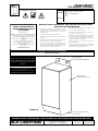
Mounting Bracket
(Mounting Hardware By Others)
NEMA 3R Rated
Stainless Steel Housing
Three (3) 7/8” Dia. Knockouts
(Not Shown)
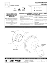
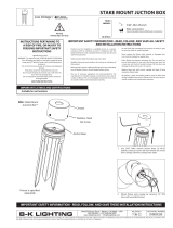
TR600 SERIES™
120V Magnetic Transformer
TR600-120
For LED sourced products, do
not exceed more than 80% of the
maximum load of the transformer.

Installation Instructions
40429 Brickyard Drive • Madera, CA 93636 • USA
559.438.5800 • FAX 559.438.5900
www.bklighting.com • [email protected]
B-K LIGHTING
IMPORTANT SAFETY INFORMATION LISTED ON REVERSE
READ, FOLLOW, AND SAVE ALL SAFETY AND INSTALLATION INSTRUCTIONS
RELEASED
02-06-18
REFERENCE NUMBER
INS-2457-00
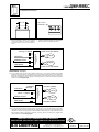
1. Mount transformer stainless steel housing
with proper hardware for surface (Hardware
By Others). Clearance holes are 4-1/4” apart on
center.
4-1/4”
(3) 7/8" Dia.
Knockouts
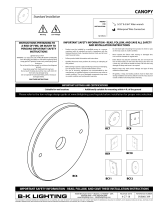
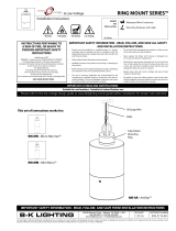
WIRING DIAGRAM - 12V Output
LINE (Black)
Fixture
COM (White)
GROUND (Green)
12VAC Secondary (Blue)
COM Secondary (Blue)
13V BOOST
(Orange - Capped)
TRANSFORMER
(in Housing)
LINE (Black)
COM (White)
GROUND (Green)
13VAC Secondary (Blue)
COM Secondary (Blue)
13V BOOST
(Orange)
(Black - Capped)
Fixture
LINE (Black)
Fixture
COM (White)
GROUND (Green)
Secondary (Red)
Secondary (Yellow)
120v
277v
TRANSFORMER
(in Housing)
TRANSFORMER
(in Housing)
60
LINE (Black)
Fixture
COM (White)
GROUND (Green)
12VAC Secondary (Red)
COM Secondary (Red)
TRANSFORMER
(in Housing)
LINE (Black)
COM (White)
GROUND (Green)
12VAC Secondary (Red)
12VAC Secondary (Red)
TRANSFORMER
(in Housing)
Fixture
Fixture
LINE (Black)
COM (White)
GROUND (Green)
13V BOOST
(Orange)
(Black - Capped)
TRANSFORMER
(in Housing)
Secondary (White)
Secondary (White)
Fixture
Fixture
LINE (Black)
COM (White)
GROUND (Green)
13V BOOST
(Orange - Capped)
TRANSFORMER
(in Housing)
12VAC Secondary (White)
12VAC Secondary (White)
Fixture
Fixture
LINE (Black)
Fixture
COM (White)
GROUND (Green)
12VAC Secondary (White)
COM Secondary (White)
13V BOOST
(Orange - Capped)
TRANSFORMER
(in Housing)
LINE (Black)
COM (White)
GROUND (Green)
13VAC Secondary (White)
COM Secondary (White)
13V BOOST
(Orange)
(Black - Capped)
Fixture
TRANSFORMER
(in Housing)
WIRING DIAGRAM - 13V Output
LINE (Black)
Fixture
COM (White)
GROUND (Green)
12VAC Secondary (Blue)
COM Secondary (Blue)
13V BOOST
(Orange - Capped)
TRANSFORMER
(in Housing)
LINE (Black)
COM (White)
GROUND (Green)
13VAC Secondary (Blue)
COM Secondary (Blue)
13V BOOST
(Orange)
(Black - Capped)
Fixture
LINE (Black)
Fixture
COM (White)
GROUND (Green)
Secondary (Red)
Secondary (Yellow)
120v
277v
TRANSFORMER
(in Housing)
TRANSFORMER
(in Housing)
60
LINE (Black)
Fixture
COM (White)
GROUND (Green)
12VAC Secondary (Red)
COM Secondary (Red)
TRANSFORMER
(in Housing)
LINE (Black)
COM (White)
GROUND (Green)
12VAC Secondary (Red)
12VAC Secondary (Red)
TRANSFORMER
(in Housing)
Fixture
Fixture
LINE (Black)
COM (White)
GROUND (Green)
13V BOOST
(Orange)
(Black - Capped)
TRANSFORMER
(in Housing)
Secondary (White)
Secondary (White)
Fixture
Fixture
LINE (Black)
COM (White)
GROUND (Green)
13V BOOST
(Orange - Capped)
TRANSFORMER
(in Housing)
12VAC Secondary (White)
12VAC Secondary (White)
Fixture
Fixture
LINE (Black)
Fixture
COM (White)
GROUND (Green)
12VAC Secondary (White)
COM Secondary (White)
13V BOOST
(Orange - Capped)
TRANSFORMER
(in Housing)
LINE (Black)
COM (White)
GROUND (Green)
13VAC Secondary (White)
COM Secondary (White)
13V BOOST
(Orange)
(Black - Capped)
Fixture
TRANSFORMER
(in Housing)
3A. For 12V output wiring: Ground incoming primary ground wire to green wire from TR600 housing. Make
watertight connections from incoming primary line voltage (black) to black primary side of transformer.
Connect incoming primary common (white) to white primary side of transformer. Orange boost wire from
primary side of transformer must be capped for 12V wiring. Connect secondary sides of transformer (white)
to fixture leads. See wiring diagram.
3B. For 13V output wiring: Ground incoming primary ground wire to green wire from TR600 housing. Make
watertight connections from incoming primary line voltage (black) to orange boost wire from primary side
of transformer. Connect incoming primary common (white) to white primary side of transformer. Black wire
from transformer primary side must be capped for 13V wiring. Connect secondary sides of transformer
(white) to fixture leads. See wiring diagram.
TR600 SERIES™
120V Magnetic Transformer
2. Stainless steel housing has three (3) 7/8” diameter
knockouts located on bottom of housing.
4-1/4”
(3) 7/8" Dia.
Knockouts

RELEASED
02-06-18
REFERENCE NUMBER
INS-2460-00
40429 Brickyard Drive • Madera, CA 93636 • USA
559.438.5800 • FAX 559.438.5900
www.bklighting.com • [email protected]
B-K LIGHTING
THIS DOCUMENT CONTAINS PROPRIETARY INFORMATION OF B-K LIGHTING, INC. AND ITS RECEIPT OR POSSESSION DOES NOT CONVEY ANY RIGHTS TO REPRODUCE, DISCLOSE ITS CONTENTS, OR TO MANUFACTURE, USE OR SELL ANYTHING IT MAY
DESCRIBE. REPRODUCTION, DISCLOSURE OR USE WITHOUT SPECIFIC WRITTEN AUTHORIZATION OF B-K LIGHTING, INC. IS STRICTLY FORBIDDEN.
IMPORTANT SAFETY INFORMATION - READ, FOLLOW, AND SAVE THESE INSTALLATION INSTRUCTIONS
TOOLS
NEEDED:
By Others
• Product must be installed by a qualified person in a manner
consistent with its intended use and in compliance with the
National Electrical Code, Canadian Electrical Code, and all Local
and Provincial Codes.
• Follow product label information and instructions.
• Qualified Personnel must perform all servicing or relamping of
this product.
• Before wiring to power supply and during servicing or relamping,
turn off power at fuse or circuit breaker before service.
• The use of accessory equipment not recommended by the
manufacturer or installed contrary to instructions may cause an
unsafe condition. The use of damaged components may cause
an unsafe condition and void product warranty.
IMPORTANT SAFETY INFORMATION - READ, FOLLOW, AND SAVE ALL SAFETY
AND INSTALLATION INSTRUCTIONS
• Do not block light emanating from product in whole or part,
as this may cause an unsafe condition.
• Never operate the fixture with missing or damaged lens.
Lens must be cleaned on regular basis.
• Entire fixture may become extremely hot. Do not touch hot
lens or fixture body. Do not touch the lamp at any time. Use
a clean, dry, soft cloth to handle the lamp. Oil from skin may
damage the lamp and cause it to rupture.
• Replace lamp only with correct wattage and type of lamp
marked on fixture label.
• All gaskets, o-rings and sealing surfaces must be kept clean
during installation and service; failure to do this may cause an
unsafe condition and void product warranty.
INSTRUCTIONS PERTAINING TO
A RISK OF FIRE, OR INJURY TO
PERSONS IMPORTANT SAFETY
INSTRUCTIONS
Lighted lamp is HOT!
WARNING - To reduce the risk of FIRE OR INJURY TO PERSONS:
Turn off/unplug and allow to cool before replacing lamp.
Lamp gets HOT quickly! Contact only switch/plug when
turning on.
Do not touch hot lens, guard, or enclosure (see diagram/
picture).
Keep lamp away from materials that may burn.
Do no touch the lamp at any time. Use a soft cloth. Oil
from skin may damage lamp.
Do not operate the luminaire fitting with a missing or
damaged shield.
SAVE THESE INSTRUCTIONS
· Suitable for wet locations
IMPORTANT LISTINGS AND CERTIFICATIONS
Warning Hot Surface
Installation Instructions
Waterproof Wire Connectors
Mounting Hardware
High Voltage
Please refer to the low voltage design
guide at www.bklighting.com/lvguide
before installation for proper wire
selection.
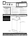
Mounting Bracket
(Mounting Hardware By Others)
NEMA 3R Rated
Stainless Steel Housing
Three (3) 7/8” Dia. Knockouts
(Not Shown)
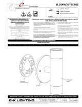
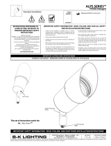
TR600 SERIES™
277V Magnetic Transformer
TR600-277
For LED sourced products, do
not exceed more than 80% of the
maximum load of the transformer.

Installation Instructions
40429 Brickyard Drive • Madera, CA 93636 • USA
559.438.5800 • FAX 559.438.5900
www.bklighting.com • [email protected]
B-K LIGHTING
IMPORTANT SAFETY INFORMATION LISTED ON REVERSE
READ, FOLLOW, AND SAVE ALL SAFETY AND INSTALLATION INSTRUCTIONS
RELEASED
02-06-18
REFERENCE NUMBER
INS-2460-00
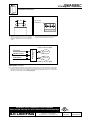
1. Mount transformer stainless steel housing
with proper hardware for surface (Hardware
By Others). Clearance holes are 4-1/4” apart on
center.
4-1/4”
(3) 7/8" Dia.
Knockouts
WIRING DIAGRAM - 12V Output
LINE (Black)
Fixture
COM (White)
GROUND (Green)
12VAC Secondary (Blue)
COM Secondary (Blue)
13V BOOST
(Orange - Capped)
TRANSFORMER
(in Housing)
LINE (Black)
COM (White)
GROUND (Green)
13VAC Secondary (Blue)
COM Secondary (Blue)
13V BOOST
(Orange)
(Black - Capped)
Fixture
LINE (Black)
Fixture
COM (White)
GROUND (Green)
Secondary (Red)
Secondary (Yellow)
120v
277v
TRANSFORMER
(in Housing)
TRANSFORMER
(in Housing)
60
LINE (Black)
Fixture
COM (White)
GROUND (Green)
12VAC Secondary (Red)
COM Secondary (Red)
TRANSFORMER
(in Housing)
LINE (Black)
COM (White)
GROUND (Green)
12VAC Secondary (Red)
12VAC Secondary (Red)
TRANSFORMER
(in Housing)
Fixture
Fixture
LINE (Black)
COM (White)
GROUND (Green)
13V BOOST
(Orange)
(Black - Capped)
TRANSFORMER
(in Housing)
Secondary (White)
Secondary (White)
Fixture
Fixture
LINE (Black)
COM (White)
GROUND (Green)
13V BOOST
(Orange - Capped)
TRANSFORMER
(in Housing)
12VAC Secondary (White)
12VAC Secondary (White)
Fixture
Fixture
LINE (Black)
Fixture
COM (White)
GROUND (Green)
12VAC Secondary (White)
COM Secondary (White)
13V BOOST
(Orange - Capped)
TRANSFORMER
(in Housing)
LINE (Black)
COM (White)
GROUND (Green)
13VAC Secondary (White)
COM Secondary (White)
13V BOOST
(Orange)
(Black - Capped)
Fixture
TRANSFORMER
(in Housing)
3A. For 12V output wiring: Ground incoming primary ground wire to green wire from TR600 housing. Make
watertight connections from incoming primary line voltage (black) to black primary side of transformer.
Connect incoming primary common (white) to white primary side of transformer. Connect secondary sides
of transformer (red) to fixture leads. See wiring diagram.
TR600 SERIES™
277V Magnetic Transformer
2. Stainless steel housing has three (3) 7/8” diameter
knockouts located on bottom of housing.
4-1/4”
(3) 7/8" Dia.
Knockouts

l
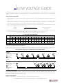
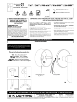
LOW VOLTAGE GUIDE
Many B-K Lighting fixtures operate on 12 volts. Taking advantage of these energy-saving fixtures requires appropriate care in planning the
electrical wiring system. To maintain expected lamp performance, we recommend the following procedures in sizing your low-voltage wiring
system.
SIZING OF LOW VOLTAGE WIRING
1. Locate and plot fixtures on plan. Choose the lighting equipment necessary to create the desired lighting effects. Mark lamp wattage for each
fixture location.
2. Identify potential transformer locations. The ideal locations are those which provide for the shortest possible low voltage distances
(inconspicuous areas, behind rocks, shrubbery, etc., within the landscape). UPM™, Power Pipe™, Power Pipe II™, or, if available, electronic
transformers integral in the fixture are good ways to hide the transformer and reduce voltage drop problems.
3. Add the total wattage for the proposed low voltage run. Measure the wire lengths from the transformer to the fixture locations. Find the
distance to the “CENTER OF LOAD” of the low voltage run.
CENTER
= Distance from first to last fixture + Distance from transformer
OF LOAD (2) Two to first fixture
4. Using the B-K Lighting Wire Selection Table, select the wattage column which applies. Look down the column stopping at a distance, in feet,
that is equal or greater than the “CENTER OF LOAD” distance. Look across to find the proper wire size for your layout.
Note: In the event of multiple runs from a given transformer, treat each run separately.
The importance of the proper wire selection is demonstrated below. Both examples have the same total watts and identical overall lengths of
wire run, yet require different wire sizes, or multiple wire runs, to operate within the 5% maximum voltage drop B-K Lighting criteria.
Note: Acceptable voltage range is 11.4 VAC minimum and 12.6 VAC maximum.
WIRE
SIZE
TOTAL WATTAGE
12 20 24 35 40 50 60 70 80 100 105 120 140 150 160 200 250
12 178 106 89 60 53 42 35 30 26 21 20 17 15 13 — — —
10 283 169 141 96 85 67 56 48 42 33 32 28 24 22 19 17 13
8450 269 225 154 135 107 90 77 67 54 51 45 38 36 31 27 21
6715 428 357 245 214 171 143 122 107 85 81 71 61 57 49 42 34
CENTER OF LOAD WIRING DISTANCES IN FEET
The Wire Selection Table provided is based on a maximum allowable voltage drop of 5%. Electrical designs which allow greater than 5% voltage
drop, reduce rated light output beyond acceptable levels.
12-VOLT WIRE SELECTION TABLE
ELECTRONIC TRANSFORMERS
For areas which are far reaching from fixtures, running 120 volt power to each fixture location with individual electronic transformers, such as
TRSS75 or TRSS150, provides an excellent economic solution to voltage drop. These transformers can also be specified in the UPM™, Power Pipe™,
Power Pipe II™ and Power Canopy™ transformer housings.
MAGNETIC TRANSFORMERS
For LED sourced products, do not exceed more than 80% of the maximum load of the transformer.
Note: Installations should be in accordance with the National Electric Code and applicable local codes.
EXAMPLE:
EXAMPLE
10'
30'
PM2RM
PM2RM
5'
25'
Total wattage:
(20w x 4) + (3w x 3) = 89 watts
CENTER OF LOAD:
(30') + 5' = 20'
2
SINGLE WIRE RUN:
12 gauge
Total wattage:
(20w x 4) + (3w x 3) = 89 watts
CENTER OF LOAD:
(10') + 25' = 30'
2
SINGLE WIRE RUN:
10 gauge
20W
3W 3W 3W
20W 20W 20W
3W 3W 3W
LVG
20W 20W 20W 20W
www.bklighting.com
-
 1
1
-
 2
2
-
 3
3
-
 4
4
-
 5
5


B-K lighting Magnetic Transformer Installation guide
- Type
- Installation guide
Ask a question and I''ll find the answer in the document
Finding information in a document is now easier with AI
Related papers
-
 B-K lighting Power Canopy Installation guide
-
 B-K lighting BC11 - 4 5/8 x 2 7/8" Rectangle Installation guide
-
 B-K lighting BC9 - 3 1/2" Square Installation guide
-
 B-K lighting BC10 - 5 x 3" Rectangle Installation guide
-
 B-K lighting BC8 - 5" Square Installation guide
-
 B-K lighting LED Lamp - MR16 Installation guide
-
 B-K lighting KMJ Installation guide
-
 B-K lighting ArtiStar Installation guide
-
 B-K lighting Alps Installation guide
-
 B-K lighting Twin Mini-Micro Installation guide


Other documents
-
 S.R.Smith poolLUX™ Plus2 Dual Transformer Installation guide
-
Intermatic PX Series Transformers Installation guide
-
RAB Lighting FERNFCC Operating instructions
-
Intermatic AL300BW Installation guide
-
 Hinkley 0900SS Installation guide
-
-
-
Intermatic PX100S Installation, Operation & Service Manual
-
Signify Hadco TBC303-15 Installation guide
-
Kichler Lighting 15PR300SS User manual

