Page is loading ...

R
N1240 / N1243 Alternators
Troubleshooting Guide
C.E. Niehoff & Co.
Page 1TG40B
CONTENTS
Section 1: Wiring ................................................................2
Section 2: CAN/J1939 Diagnostics ...................................3
Section 3: Basic Troubleshooting .....................................4
Section 4: Advanced Troubleshooting .............................5
Battery Charging Conditions
The following conditions may be observed during cold-
start voltage tests until temperatures of electrical system
components stabilize. The time it takes to reach optimum
voltage and amps will vary with engine speed, load, and
ambient temperature.
Maintenance/Low Maintenance Lead-Acid Battery:
Traditional lead acid batteries require lowest charge volt-
age of all vehicle battery chemistries. Battery cells must
be maintained by periodically topping off with distilled
water as required.
Maintenance-free Lead-Acid Battery:
Maintenance-free batteries are similar to Maintenance/
Low Maintenance batteries, but may require slightly higher
charge voltage.
Deep-cycle/Marine Maintenance-free Battery:
Charge acceptance of these batteries may display charac-
teristics similar to maintenance-free batteries and may
charge faster due to generally lower capacity relative to
size.
AGM (Absorbed Glass Mat) Maintenance-free Battery:
These dry-cell batteries respond better than standard
maintenance-free batteries. If battery state of charge
(SOC) drops to 75% or less, batteries should be
recharged to 95% or higher separately from engine charg-
ing system to avoid damaging charging system
components and to provide best overall performance.
Charge acceptance of these batteries may display
charac-
teristics similar to maintenance batteries, but may require
higher charge voltage and will draw signicant current (<100
amps) when under 50% SOC.
Lithium Battery:
Lithium batteries have unique charging characteristics that
differ from lead acid. These batteries require charging
systems congured specically for lithium battery chemis-
tries. Contact CEN for more information on lithium battery
charging systems and components.
Voltage testing:
• Set meter to proper scale and type (AC or DC).
• Be sure to zero the meter scale or identify the meter
burden by touching meter leads together. Meter burden
must be subtracted from nal reading obtained.
• Be sure the meter leads touch source area only.
Prevent short circuit damage to test leads or source by
not allowing meter leads to touch other pins or exposed
wires in test area.
• Be sure to use CEN tools designed especially for trou-
bleshooting CEN alternators when available.
Resistance (ohm) testing:
• Set meter to proper scale.
• Be sure to zero the meter scale or identify the meter
burden by touching meter leads together. Meter burden
must be subtracted from nal reading obtained.
• Be sure meter leads touch source area only. Allowing
ngers or body parts to touch meter leads or source
during reading may alter reading.
• Be sure reading is taken when source is at 70ºF. Read-
ings taken at higher temperatures will increase the
reading. Conversely, readings taken at lower tempera-
tures will decrease the reading.
• Be sure to test directly at the source. Testing through
extended harnesses or cable extensions may increase
the reading.
• "OL" as referenced in this document refers to open cir-
cuit: "innite" resistance, typically in very high kilo- or
megaohm range depending on meter and settings.
Diode testing:
• Diodes allow current to ow in one direction only. Typi-
cal voltage drop in forward bias can range from 0.1-
0.85V. Meter should read OL in reverse bias. Check
meter user manual for meter-specic testing guidelines.
Voltage drop testing:
• Measure voltage between B+ on alternator or power
source and B- (ground) on alternator or source. Record
reading. Move to batteries or other power source and
measure again between B+ and B- terminals on battery
or other power source. The difference between the two
readings represents voltage lost within circuit due to,
but not limited to, inadequate cable gauge or faulty con-
nections.
• Voltage drop measurements must be taken with all elec-
trical loads or source operating.
Dynamic/Live testing (Connecting power and ground to
component to test operation/function out of circuit):
• Connect jumper leads directly and securely to power
source contacts of component being tested.
• Make any connection to power and ground at power
supply or battery source terminals. Do not make con-
nection at component source terminals, as that may
create an arc and damage component source terminals.
Testing Guidelines
Professional service technicians rely on the following
guidelines when testing electrical components.

Page 2 TG0040A
Section 1: Wiring Diagram
CEN N1240-3/N1243-2 Alternators
Description and Operation
N1240-3 and N1243-2 28 V 260 A alternators are
internally rectified. All windings and current-conduct-
ing components are non-moving, so there are no
brushes or slip rings to wear out.
After engine is running, N3218 regulator receives
energize signal. Regulator monitors alternator
rotation and provides field current only when it
detects alternator shaft rotating at or above idle
speed.
After regulator detects alternator rotation, it gradu-
ally applies field current, preventing an abrupt
mechanical load on accessory drive system. The soft
start may take up to 20 seconds.
N3218 regulator used with these units also
• is negative temperature compensated. Setpoint is
28.8 ± 0.5 V at 72 F when configured to operate
with 6TMF type batteries.
• provides overvoltage cutout (OVCO). Regulator
will trip OVCO when system voltage rises above
setpoint by 3 V for longer than 3 seconds. OVCO
feature detects high voltage and reacts by opening
alternator field circuit and turning off alternator.
Restarting engine or waiting until system voltage
drops 5 V below setpoint will reset OVCO circuit.
• maintains alternator steady-state output voltage
at regulated settings as vehicle electrical loads are
switched on and off.
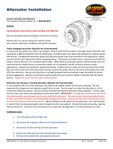
Figure 2 — N1240-3/N1243-2 Alternators with N3218 Regulator
Figure 1 — N1240-3/N1243-2 Alternators and
N3218 Regulator Terminals
B+ terminal
(next to regulator connector)
TT
TT
T
IGN terminal
B–
terminal
TT
TT
T
TT
TT
T
R
Section 1: Wiring Diagram
Page 2 TG40B

Page 3
TG0040A
Section 2: CAN/J1939 Diagnostics
CAN/J1939 Interface
DESCRIPTION AND OPERATION
The CEN N3218 digital regulator is compatible with
SAE J1939 communications standard for vehicle
networking.
CEN uses MIL-STD connector MS3112E12-10P to
interface between the N3218 and the vehicle J1939
databus and battery box sensors. Mating connector is
MS3116E12-10S or equivalent. If this connection is
not used, it must be sealed with connector cover
MS3181-12CA or equivalent. Connector pinout is
shown in Table 1. Message content is shown in Table 2.
Battery box sensing inputs connect to battery pack
positive terminal (pin J) and battery box thermistor
(pin H). Thermistor is 10K NTC with 32650Ω at 0ºC,
10000Ω at 25ºC, 3601Ω at 50ºC and 1% inter-
changeability. Thermistor location should be chosen
so that it closely represents battery case tempera-
ture. Thermistor connects between pin H and vehicle
chassis, battery pack negative terminal, or negative
bus bar. If either sensing input (pin H or J) is not
used, regulator will default to internal temperature
and alternator voltage.
Pin Identification
TABLE 1 – J1939 Connector
Circuit Identification
A
B
C
D
E
F
G
H
J
K
J1939+
J1939–
J1939/SHLD
B–/GND
Mfr use only
Mfr use only
Mfr use only
Ext. Temp. Sense
Ext. Voltage Sense
unused
Figure 3 – J1939
Connector Pins
Regulator Readout Expected Reading
TABLE 2 – N3218 Regulator/J1939 Readout Diagnostics (see Table 3)
Action If Expected Reading Not Present
Alternator Speed
Alternator Voltage
Battery Voltage
Regulator Temp.
Alternator Current
Alternator Load
Battery Temp.
Stator Voltages
1500 to 8000 RPM
26 to 30 V (when charging)
26 to 30 V (when charging)
–40 to 125ºC
0 to 300 A
0 to 100%
–40 to 80ºC
10 to 18 V (when charging)
Check belts and pulley.
Check alternator drive and regulator IGN signal.
Check battery box voltage sense signal.
Check regulator.
Check alternator output cabling.
Check alternator output cabling.
Check battery box thermistor.
Check alternator belts and output.
Notes:
(1) Byte 1 broadcast closest to CAN frame ID.
(2) Contact C. E. Niehoff & Co. for definition of custom proprietary message content.
Table 3 — Message Data
PGN Name 1 (1) 2 3 4 5 6 7 8
FED5 Alt. Speed Alt. Speed
FEF7 Alt. Voltage Alt. Voltage Batt. Voltage
FEA7 Alt. Temp. Reg. Temp.
FFC8 Proprietary #1 Alt. Current (2) (2) Alt. Hrs. Load Batt. Temp.
FFC9 Proprietary #2 (2) (2) OVCO Count (2) (2) (2) (2) (2)
FFCA Proprietary #3 Stator 1 Voltage Stator 2 Voltage
R
Section 2: CAN/J1939 Diagnostics
Page 3TG40B

Page 4 TG0040A
Section 3: Basic Troubleshooting
D. Basic Troubleshooting
1. Inspect charging system components
Check connections at ground cables, positive
cables, and regulator harness. Repair or replace
any damaged component before troubleshooting.
2. Inspect connections of vehicle batteries
Connections must be clean and tight.
3. Determine battery type, voltage, and state
of charge
Batteries must be all the same type for system
operation. If batteries are discharged, recharge
or replace batteries as necessary. Electrical
system cannot be properly tested unless batter-
ies are charged 95% or higher. See page 1 for
details.
A. Tools and Equipment for Job
• Digital Multimeter (DMM)
• Ammeter (digital, inductive)
• Jumper wires
B. Identification Record
List the following for proper troubleshooting:
Alternator model number ____________________
Regulator model number _____________________
❏
❏
CAUTION
SYMPTOM ACTION
TABLE 4 – System Conditions
Check: loose drive belt; low
battery state of charge.
Check: current load on system
is greater than alternator
can produce.
Check: defective wiring or poor
ground path.
Check: defective alternator
and/or regulator.
Check: defective regulator.
Check: alternator.
Check: presence of energize
signal to E terminal on
regulator.
Check: battery voltage at alter-
nator output terminal.
Check: defective alternator
and/or regulator.
Low Voltage Output
High Voltage Output
No Voltage Output
TROUBLESHOOTING
Shut down vehicle and restart engine. If alternator
functions normally after restart, a “no output condi-
tion” was normal response of voltage regulator to
overvoltage condition. Inspect condition of electrical
system.
If you have reset alternator once, and electrical
system returns to normal charge voltage condition,
there may have been a one time, overvoltage spike
that caused OVCO circuit to trip.
If OVCO circuit repeats cutout a second time in short
succession and shuts off alternator field circuit, try
third restart. If OVCO circuit repeats cutout a third
time, go to Chart 1, page 5.
C. Preliminary Check-out
Check symptoms in Table 4 and correct as necessary.
4. Connect meters to alternator
Connect red lead of DMM to alternator B+
terminal and black lead to alternator B–
terminal. Clamp inductive ammeter on B+
cable.
5. Operate vehicle
Observe charge voltage.
If charge voltage is above
33 volts, immediately shut
down system. Electrical
system damage may occur
if charging system is
allowed to operate at
excessive voltage. Go to
Table 4 at left.
If voltage is at or below regulator setpoint, let
charging system operate for several minutes to
normalize operating temperature.
6. Observe charge volts and amps
Charge voltage should increase and charge amps
should decrease. If charge voltage does not in-
crease within ten minutes, continue to next step.
7. Batteries are considered fully charged if charge
voltage is at regulator setpoint and charge amps
remain at lowest value for 10 minutes.
8. If charging system is not performing properly,
go to Chart 1, page 5.
R
Section 3: Basic Troubleshooting
Page 4 TG40B

Page 5
TG0040A
Section 4: Advanced Troubleshooting
Figure 4 – Alternator-to-Regulator Harness Plug
PIN CONNECTIONS
Pin A F–
Pin B Phase 1
Pin C GND/B–
Pin D B+
Pin E Kelvin –
Pin F F+
Pin G Kelvin +
Pin H Phase 2
Chart 1 – No Alternator Output – Quick Diagnostic
With engine running: Does battery voltage exist at alternator B+ terminal and regulator IGN terminal?
Yes No
Repair vehicle harness circuit to IGN terminal on
regulator or B+ terminal on alternator.
TT
TT
T
TT
TT
T
With key off, engine off: Unplug alternator-to-regulator harness. Connect DMM on DC volt scale across pins
C and D. Does battery voltage exist?
Yes No
With DMM on resistance scale, does the field resistance between pins F and A in harness plug measure about
1.4 (±0.2) ohms?
Yes No
Alternator is defective.
TT
TT
T
TT
TT
T
Alternator is defective.
TT
TT
T
TT
TT
T
With key off, engine off: Does battery voltage exist at alternator B+ terminal?
Yes No
Repair vehicle harness circuit to B+ terminal on alternator.
TT
TT
T
TT
TT
T
Set DMM to diode test. Check continuity of thermal switch and rear stator diodes: Connect red lead to pin B
in harness plug. Connect black lead to alternator B+ terminal. Meter should read one diode drop (approx.
0.6 to 0.9 V). Disconnect leads. Connect red lead to alternator B– terminal. Connect black lead to pin B.
Meter should read one diode drop (approx. 0.6 to 0.9 V).
Yes No
Alternator is defective.
TT
TT
T
TT
TT
T
Set DMM to diode test. Check continuity of front stator diodes: Connect red lead to pin H in harness plug.
Connect black lead to alternator B+ terminal. Meter should read one diode drop (approx. 0.6 to 0.9 V).
Disconnect leads. Connect red lead to alternator B– terminal. Connect black lead to pin H. Meter should read
one diode drop (approx. 0.6 to 0.9 V).
Yes No
Alternator is defective.
TT
TT
T
TT
TT
T
Go to Page 6 to continue.
R
Section 4: Advanced Troubleshooting
Page 5TG40B

Page 6 TG0040A
Section 4: Advanced Troubleshooting
Figure 5 – Alternator-to-Regulator Harness Plug
PIN CONNECTIONS
Pin A F–
Pin B Phase 1
Pin C GND/B–
Pin D B+
Pin E Kelvin –
Pin F F+
Pin G Kelvin +
Pin H Phase 2
Chart 1 cont’d from Page 5 – No Alternator Output – Quick Diagnostic
Momentarily (1 sec.) jumper pin F in harness plug to alternator B+ terminal. Touch shaft with steel tool to
detect significant magnetism. Is shaft magnetized?
Yes No
Alternator is defective.
TT
TT
T
Regulator is defective.
TT
TT
T
TT
TT
T
Yes No
Alternator is defective.
TT
TT
T
(CONT’D)
With DMM on resistance scale: Connect red lead to pin E in harness plug. Connect black lead to alternator
B+ terminal. Meter should read 0 ohms. Change pin E to pin G. Meter should read 0 ohms.
R
Section 4: Advanced Troubleshooting
Page 6 TG40B

Page 7
TG0040A
Notes
R
Page 7TG40B
If you have questions about your alternator or any of these test procedures, or if you need to locate a Factory Authorized Service Distributor, please contact us at:
C. E. Niehoff & Co.• 2021 Lee Street • Evanston, IL 60202 USA
TEL: 800.643.4633 USA and Canada • TEL: 847.866.6030 outside USA and Canada • FAX: 847.492.1242
E-mail us at service@CENiehoff.com
/