Page is loading ...

Manky Fruit
Deliciously tweaked take
on an op-amp Big Muff Pi
Contents of this document are ©2023 Pedal Parts Ltd.
No reproduction permitted without the express written
permission of Pedal Parts Ltd. All rights reserved.

Important notes - DO NOT SKIP!
If you’re using any of our footswitch daughterboards,
DOWNLOAD THE DAUGHTERBOARD DOCUMENT
•Download and read the appropriate build document for the daughterboard as well as
this one BEFORE you start the build.
•DO NOT solder the supplied Current Limiting Resistor (CLR) to the main circuit board
even if there is a place for it. This should be soldered to the footswitch daughterboard.
This applies to older PCBs with a pad marked LED next to the IN V G OU pads.
POWER SUPPLY
Unless otherwise stated in this document this circuit is designed to be powered with
9V DC Tip-Negative supply.
COMPONENT SPECS
Unless otherwise stated in this document:
•Resistors should be 0.25W. You can use those with higher ratings but check the
physical size of them. For kits that use 3mm resistors instead of standard 6mm, these
will usually be either 0.125W or 0.4W.
•Electrolytics caps should be at least 25V for 9V circuits, 35V for 18V circuits. Again,
check physical size if using higher ratings.
LAYOUT CONVENTIONS
Unless otherwise stated in this document, the following are used:
Electrolytic capacitors:
Long leg (anode) to square pad. Stripe indicates cathode.
Diodes/LEDs:
Striped leg (cathode) to square pad. Short leg to square pad for LEDs.
The exception to this is with Russian germanium diodes - stripe = anode.
•ICs:
Square pad indicates pin 1.

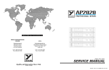
Schematic + BOM
R1 1M
R2 470K
R3 470K
R4 22K
R5 10K
R6 47K
R7 5K6
R8 15K
R9 220R
R10 100K
R11 5K6
R12 3K9
R13 1K5
R14 27K
R15 10K
R16 10K
R17 220K
C1 10n
C2 470n
C3 4n7
C4 4n7
C5 1u
C6 10u elec
C7 330p
C8 100n
C9 1u
C10 1u
C11 100n
C12 10u elec
U$2 100u elec
(Yes, we missed
changing the name
on the PCB)
D1-2 3mm red LEDs
D3 1N5817
IC1 TL074
BUZZ 100KC*
TONE 10KB
VOL 50KA
S1 SPDT ON-OFF-ON
*Reported as 100KB on the
trace, but no way. It needs to
be reverse log to be even
vaguely useable.


PCB layout ©2023 Pedal Parts Ltd.
The power and signal pads on the PCB conform
to the FuzzDog Direct Connection format, so can
be paired with the appropriate daughterboard for
quick and easy offboard wiring. Check the
separate daughterboard document for details.
Be very careful when soldering the diodes.
They’re very sensitive to heat. You should use
some kind of heat sink (crocodile clip or reverse
action tweezers) on each leg as you solder them.
Keep exposure to heat to a minimum (under 2
seconds). Same goes for the IC if you aren’t
using a socket.
Snap the small metal tag off the pots so they can
be mounted flush in the box.
You should solder all other board-mounted
components before you solder the pots and
switches. Once they’re in place you’ll have no
access to much of the board. Make sure your
pots all line up nicely.
The best way to do that is to solder
a single pin of each pot in place then melt and
adjust if necessary before soldering in the other
two pins. Same procedure for the toggle switch.

Test the board!
Check the relevant daughterboard document for more
info before you undertake this stage.
UNDER NO CIRCUMSTANCES will troubleshooting help
be offered if you have skipped this stage. No exceptions.
Once you’ve finished the circuit it makes sense to test is before starting on the switch and LED
wiring. It’ll cut down troubleshooting time in the long run. If the circuit works at this stage, but it
doesn’t once you wire up the switch - guess what? You’ve probably made a mistake with the switch.
Solder some nice, long lengths of wire to the board connections for 9V, GND, IN and OUT. Connect
IN and OUT to the jacks as shown. Connect all the GNDs together (twist them up and add a small
amount of solder to tack it). Connect the battery + lead to the 9V wire, same method. Plug in. Go!
If you’re using a ribbon cable you can tack the wires to the ends of that. It’s a lot easier to take them
off there than it is do desolder wires from the PCB pads.
If it works, carry on and do your switch wiring. If not... aw man. At least you know the problem is
with the circuit. Find out why, get it working, THEN worry about the switch etc.
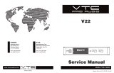
Your completed circuit board
including pots

Now’s the time
to refer to the
daughterboard
document for
your chosen
bypass method.
Enjoy your pedal!

This template is a rough guide only. You should ensure correct marking of your
enclosure before drilling. You use this template at your own risk.
Pedal Parts Ltd can accept no responsibility for incorrect drilling of enclosures.
FuzzDog.co.uk
Recommended drill sizes:
Pots 7mm
Jacks 10mm
Footswitch 12mm
DC Socket 12mm
Toggle switches 6mm
32mm
Drilling template
without battery - side DC
Hammond 1590B - 60 x 111 x 31mm
It’s a good idea to drill the pot and
toggle switch holes 1mm bigger if
you’re board-mounting them.
Wiggle room = good!
22mm
2mm
/