CO2 or Nitrogen Regulator (Double Dispense
Tower)
Your beverage dispenser comes equipped with a 5 pound
tank and a dual gauge regulator. The lower gauge should
EHUHDGLQJDSSUR[LPDWHO\SVLEDUZKHQWKHWDQNLV
SURSHUO\¿OOHGDQGWKHWDQNLVQRWLQWKHUHIULJHUDWRUDWURRP
WHPSHUDWXUH7KHWDQNZLOOUHDGOHVVZKHQFKLOOHG8VHWKLV
lower gauge as an indicator of how much CO2 or nitrogen
you have left in the tank.
The upper gauge reads the pressure being supplied to the
beverage keg. Follow the procedure below to adjust the
pres-VXUHWRSVLWREDUIRUODJHUEHHURU
SVL WREDUIRUDOHV
To adjust the pressure (Upper Gauge):
1. Close the shutoff valves at the bottom of the regulator.
2. Be sure the faucet handle is closed on the tower.
3. Loosen the lock nut by turning ඞ counterclockwise us-
ing the 1»2" open end wrench until loose, this will allow
adjustment of the pressure adjustment screw.
4. :LWKWKHIODWEODGHGVFUHZGULYHUWXUQWKHDGMXVWPHQW
screw ඟclockwise to increase the pressure or ඞcoun-
terclockwise to decrease the pressure.
5. Open the shutoff valve on the bottom of the regulator.
The gauge reading may drop but will return very
quickly.
6. 3XOOWKHULQJRQWKHNHJFRXSOHUWRDOORZWKHJDVWRIORZ
momentarily.
7. 0DNHDQ\ILQHDGMXVWPHQWVLIQHFHVVDU\ZLWKWKH
DGMXVWment screw.
8. Tighten the locknut with the 1»2" open end wrench by
turning clockwise ඟ
CO2 or Nitrogen Regulator (Single Dispense
Tower)
Your beverage dispenser comes equipped with a 5 pound
tank and a single gauge regulator. The gauge reads the
pressure being supplied to the beverage keg. Follow the
proce-dure below to adjust the pressure to 12 - 14 psi (0.8
to 1 bar) for lager beer or 9-12 psi (0.6 to 0.8 bar) for
DOHV
To adjust the pressure (Single Gauge):
1. Close the shutoff valve at the bottom of the regulator.
2. Be sure the faucet handle is closed on the tower.
3. Loosen the lock nut by turning ඞ counterclockwise us-
ing the 1»2" open end wrench until loose, this will allow
adjustment of the pressure adjustment screw.
4. :LWKWKHIODWEODGHGVFUHZGULYHUWXUQWKHDGMXVWPHQW
screw ඟclockwise to increase the pressure or ඞcoun-
terclockwise to decrease the pressure.
5. Open the shutoff valve on the bottom of the regulator.
The gauge reading may drop but will return very
quickly.
6. 3XOOWKHULQJRQWKHNHJFRXSOHUWRDOORZWKHJDVWRIORZ
momentarily.
7. 0DNHDQ\ILQHDGMXVWPHQWVLIQHFHVVDU\ZLWKWKH
DGMXVW-ment screw.
8. Tighten the locknut with the 1»2" open end wrench by
turning clockwise ඟ
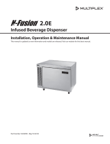
Ring on keg
coupler
(Regulator for 6LQJOH
'LVSHQVH7RZHU
(Regulator for 'RXEOH
'LVSHQVH7RZHU
VKXWRII
valves (closed
SRVLWLRQVKRZQ
Upper Gauge
Pressure Gauge
Lower Gauge
Pressure
Adjustment
Screw Lock Nut
Pressure
Adjustment
Screw
Lock Nut
shutoff valve
(closed posi-
WLRQVKRZQ
USING YOUR BEVERAGE DISPENSER
19