
WIFLY PAR QA5
User Manual

2
©2022 ADJ Products, LLC all rights reserved. Information, specications, diagrams, images, and
instructions herein are subject to change without notice. ADJ Products, LLC logo and identifying
product names and numbers herein are trademarks of ADJ Products, LLC. Copyright protection
claimed includes all forms and matters of copyrightable materials and information now allowed by
statutory or judicial law or hereinafter granted. Product names used in this document may be trade-
marks or registered trademarks of their respective companies and are hereby acknowledged. All
non-ADJ Products, LLC brands and product names are trademarks or registered trademarks of their
respective companies.
ADJ Products, LLC and all aliated companies hereby disclaim any and all liabilities for property,
equipment, building, and electrical damages, injuries to any persons, and direct or indirect economic
loss associated with the use or reliance of any information contained within this document, and/or as
a result of the improper, unsafe, insucient and negligent assembly, installation, rigging, and opera-
tion of this product.
Europe Energy Saving Notice
Energy Saving Matters (EuP 2009/125/EC)
Saving electric energy is a key to help protecting the enviroment. Please turn o all electrical products when
they are not in use. To avoid power consumption in idle mode, disconnect all electrical equipment from power
when not in use. Thank you!
Date Document
Version
Software
Version DMX Channels Notes
08/2015 1.0 2.06 1 / 2 / 3 / 4 / 5 / 6 / 7 /
8 ch. Initial Release
01/18/2022 1.1 N/C No change Corrected DMX Traits
DOCUMENT VERSION
Due to additional product features and/or enhancements, an updated version of
this document may be available online.
Please check www.adj.com for the latest revision/update of this manual
before beginning installation and/or programming.

3
TABLE OF CONTENTS
Introduction 4
General Instructions | Warranty Registration | Installation 5
Safety Precautions 6
Battery Precautions 7
DMX Setup 9
Operating Instructions 11
Primary-Secondary Conguration | Power Cord Daisy Chain 15
Wiy Setup 16
ADJ RFC Operation 17
DMX Traits 18
Battery Information 22
Battery Replacement 23
Re-Initialization 24
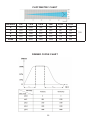
Photometric Chart | Dimmer Curve Chart 25
Fuse Replacement | Trouble Shooting | Cleaning 26
Warranty 27
Specications 28

4
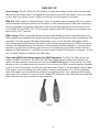
Unpacking: Thank you for purchasing the WiFly Par QA5 by ADJ Products, LLC. Every WiFly Par QA5
has been thoroughly tested and has been shipped in perfect operating condition. Carefully check the
shipping carton for damage that may have occurred during shipping. If the carton appears to have
been damaged, carefully inspect your xture for any damage and be sure all accessories necessary
to operate the unit have arrived intact. In the event that damage has been found or parts are missing,
please contact our toll free customer support number for further instructions. Do not return this unit to
your dealer without rst contacting customer support.
Introduction: The WiFly Par QA5 is a rechargeable lithium battery powered, DMX intelligent, LED par
xture with ADJ’s WiFly Transceiver with wireless DMX built-in. This unit gives you the freedom to
set up your xture wherever you wish without the restrictions of power or DMX cabling. The built-in
battery will keep charge for up to 6 hours (full on) from a full, single charge. This xture can be used in
stand alone mode or connected in a Primary/Secondary conguration. This wash has ve operating
modes: Sound Active mode, Auto mode, RGB mode, Static Color mode, and DMX control mode.
Customer Support: ADJ Products, LLC provides a toll free customer support line to provide set up
help and to answer any questions that may arise during set up or initial operation. You may also visit
us on the web at www.adj.com for any comments or suggestions. Service Hours are Monday through
Friday 8:00 a.m. to 4:30 p.m. Pacic Standard Time.
Voice: (800) 322-6337
Fax: (323) 582-2941
E-mail: [email protected]
Warning! To prevent or reduce the risk of electrical shock or re, do not expose this unit to rain or moisture.
Caution! There are no user serviceable parts inside this unit. Do not attempt any repairs yourself, as doing
so will void your manufacturer’s warranty. In the unlikely event your unit may require service, please con-
tact ADJ Products, LLC.
PLEASE recycle the shipping carton when ever possible.
INTRODUCTION

5
• Rechargeable Lithium Battery
• Multi-Colors
• Five Operating Modes
• Electronic Dimming 0-100%
• Built in Microphone
• DMX-512 protocol
• 3-Pin & 5-Pin DMX Connection
• 8 DMX Channel Modes: 1 Channel Mode, 2 Channel Mode, 3 Channel Mode, 4 Channel Mode, 5
Channel Mode, 6 Channel Mode, 7 Channel Mode, & 8 Channel Mode
• Built-In ADJ’s WiFly TransCeiver Wireless DMX
• ADJ RFC compatiable (Not Included)
• Power Cord Daisy Chain (see Power Cord Daisy Chain section of this manual)
FEATURES
The WiFly Par QA5 carries a 2 year limited warranty. Please fill out the enclosed warranty card to
validate your purchase. All returned service items, whether under warranty or not, must be freight
pre-paid and accompanied by a return authorization (R.A.) number. The R.A. number must be clearly
written on the outside of the return package. A brief description of the problem as well as the R.A.
number must also be written down on a piece of paper included in the shipping carton. If the unit is
under warranty, you must provide a copy of your proof of purchase invoice. You may obtain an R.A.
number by contacting our customer support team on our customer support number. All packages
returned to the service department not displaying an R.A. number on the outside of the package will
be returned to the shipper.
WARRANTY REGISTRATION
The unit should be mounted using a mounting clamp (not provided), and affixing it to the mounting
bracket that is provided with the unit. Always ensure that the unit is firmly fixed to avoid vibration
and slipping while operating. Always ensure that the structure that you are attaching the unit to is
secure and is able to support at least 10 times the unit’s weight. In addition, always use a safety
cable that can hold 12 times the weight of the unit when installing the fixture.
The equipment must be installed by a professional, and it must be installed in a place where it is out
of the reach of the general public.
INSTALLATION

6
• To reduce the risk of electrical shock or fire, do not expose this unit to rain or moisture.
• Do not spill water or other liquids into or on to your unit.
• Do not attempt to operate this unit if the power cord is frayed or broken.
• Do not attempt to remove or break off the ground prong from the electrical cord. This prong is
used to reduce the risk of electrical shock and fire in the event of an internal short.
• Disconnect from main power before making any type of connection.
• Do not remove the cover for any reason. There are no user serviceable parts inside.
• Never operate this unit with the cover removed.
• Never plug this unit into a dimmer pack.
• Always be sure to mount this unit in an area that will allow proper ventilation. Allow about 6”
(15cm) between this device and a wall.
• Do not attempt to operate this unit if it has been damaged in any way.
• This unit is intended for indoor use only. Use of this product outdoors voids all warranties.
• During long periods of non-use, disconnect the unit’s main power.
• Always mount this unit in safe and stable matter.
• Power-supply cords should be routed in such a way that that they are not likely to be walked
on or pinched by items placed upon or against them, paying particular attention to the point at
which they exit from the unit.
• Cleaning - The fixture should be cleaned only as recommended by the manufacturer. See the
Cleaning section of this manual for details.
• Heat - The appliance should be situated away from heat sources such as radiators, heat regis-
ters, stoves, or other appliances (including amplifiers) that produce heat.
• The fixture should be serviced by qualified service personnel when:
A. The power-supply cord or the plug has been damaged.
B. Objects have fallen, or liquid has been spilled into the appliance.
C. The appliance has been exposed to rain or water.
D. The appliance does not appear to operate normally or exhibits a marked change in perfor-
mance.
CAUTION: Like any wireless device, this unit is highly susceptible to static electricity. Static
electricity can severly damage the unit. Before touching the antenna, please ground/discharge
yourself.
SAFETY PRECAUTIONS

7
BATTERY PRECAUTIONS
1. HANDLING OF BATTERIES
1.1 Do Not Short Circuit the Battery
Avoid short circuiting the battery. Doing so generates a very high current and battery overheating,
which may result in electrolyte gel leakage, harmful fumes, or explosion. The LIR tabs are suscepti-
ble to short circuiting when placed on conductive surfaces. A short circuit may lead to heat build up
and damage to the battery. Protective circuitry with PCM is employed to protect against accidental
short circuiting of the battery pack.
1.2 Mechanical shock
Drops, impact hits, bending, etc. may cause failure or shortend life of the LIR battery.
2. OTHER
2.1 Battery connection
• Direct soldering of wire leads or devices to the battery is strictly prohibited.
• Lead tabs with pre-soldered wiring shall be spot welded to the batteries. Do not attempt direct
soldering, as this may cause damage to battery components, such as the separator or insulator,
due to heat build up.
2.2 Prevention of short circuit within a battery pack
There are sufficient layers of insulation between wiring and the batteries to provide extra protection
against short circuiting. The battery pack is constructed in such a way as to prevent short circuits
that could create a risk of fire or smoke.
2.3 Do No Disassemble the Batteries
• Never disassemble the batteries. Doing so may cause an internal short circuit in the battery, which
may lead to harmful fumes, fire, explosion, or other hazards.
• Electrolyte Gel is extremey harmful. Electrolyte Gel should not leak from the LIR battery. Should
the electrolyte gel come into contact with the skin or eyes, flush the area of contact immediately
with fresh water and seek medical attention immediately.
2.4 Do Not Expose the Battery to Heat or Fire
Never incinerate or dispose of the batteries in fire. This could result in an explosion and other haz-
ards.
2.5 Do Not Expose the Battery to water or liquids
Never soak/drop the batteries in liquids such as water, seawater, or beverages such as soft drinks,
juices, or coffee.
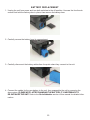
2.6 Battery Replacement
For battery replacement please contact ADJ customer support (800) 322-6337.

8
BATTERY PRECAUTIONS
2.7 Do Not use a damaged Battery
There is the possibility that the battery could be damaged during shipping. Should the battery be
found damaged, including damage to the plastic casing of the battery, deformation of the battery
package, emission of electrolyte odors, leakage of the electrolyte gel, or other concerns, DO NOT
use the battery. A battery with a odor of electrolyte or a gel leakage should be placed away from fire
to avoid fire or explosion.
3. BATTERY STORAGE
When storing the battery, it should be stored at room temperature, with a charge of at least 50%. It is
recommended that the battery be charged every 6 months during long periods of storage. Doing so
will prolong the life of the battery and will also ensure battery is charged and ready for use.
4. OTHER CHEMICAL REACTIONS
Because batteries utilize a chemical reaction, battery performance will deteriorate over time, even if
stored for a long period of time without being used. In addition, if various usage conditions, such as
charge, discharge, ambient temperature, etc, are not maintained within the specified ranges, the life
expectancy of the battery maybe shortened or the device in which the battery is used may be dam-
aged by electrolyte gel leakage. If the batteries cannot maintain a charge for long periods of time,
even when they are charged correctly, this may indicate it is time to change the battery.
5. BATTERY DISPOSAL
Please dispose of depleted batteries according to local regulations.

9
DMX SET UP
Power Supply: The ADJ WiFly Par QA5 features an automatic voltage switch, which will automati-
cally sense the voltage when it is plugged into the power source. With this switch, there is no need
to worry about the correct power voltage, and this unit can be plugged in anywhere.
DMX-512: DMX is short for Digital Multiplex. This is a universal protocol used as a form of commu-
nication between intelligent fixtures and controllers. A DMX controller sends DMX data instructions
from the controller to the fixture. DMX data is sent as serial data that travels from fixture to fixture
via the DATA “IN” and DATA “OUT” XLR terminals located on all DMX fixtures (most controllers only
have a DATA “OUT” terminal).
DMX Linking: DMX is a language allowing all makes and models of different manufacturers to be
linked together and operate from a single controller, as long as all fixtures and the controller are DMX
compliant. To ensure proper DMX data transmission, try to use the shortest cable path possible
when linking several DMX fixtures. The order in which fixtures are connected in a DMX line does not
influence the DMX addressing. For example, a fixture assigned a DMX address of 1 may be placed
anywhere in a DMX line: at the beginning, at the end, or anywhere in the middle. When a fixture is
assigned a DMX address of 1, the DMX controller knows to send DATA assigned to address 1 to that
unit, no matter where it is located in the DMX chain.
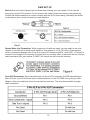
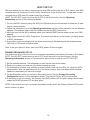
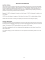
Data Cable (DMX Cable) Requirements (For DMX Operation): The WiFly Par QA5 can be con-
trolled via DMX-512 protocol. The WiFly Par QA5 has 8 DMX channel modes, and detailed infor-
mation on these channels modes can be found in the DMX Traits section of this manual. The DMX
address is set on the back panel of the device. Your unit and your DMX controller require a standard
3-pin or 5-pin XLR connector for data input and data output (Figure 1). We recommend Accu-Cable
DMX cables. If you are making your own cables, be sure to use standard 110-120 Ohm shielded
cable (This cable may be purchased at almost all pro lighting stores). Your cables should be made
with a male XLR connector at one end and a female XLR connector at the other. Also remember that
DMX cable must be daisy chained and cannot be split.

10
DMX SET UP
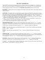
Notice: Be sure to follow figures two and three when making your own cables. Do not use the
ground lug on the XLR connector. Do not connect the cable’s shield conductor to the ground lug
or allow the shield conductor to come in contact with the XLR’s outer casing. Grounding the shield
could cause a short circuit and result in erratic behavior.
Special Note: Line Termination. When longer runs of cable are used, you may need to use a ter-
minator on the last unit to avoid erratic behavior. A terminator is a 110-120 ohm 1/4 watt resistor,
which is connected between pins 2 and 3 of a male XLR connector (DATA + and DATA -). This unit is
inserted in the female XLR connector of the last unit in your daisy chain to terminate the line. Using a
cable terminator (ADJ part number Z-DMX/T) will reduce the risk of erratic behavior.
5-pin XLR Connectors. Some manufacturers use 5-pin XLR connectors for DATA transmission in
place of 3-pin. 5-pin XLR fixtures may be implemented in a 3-pin XLR DMX line by using a cable
adaptor, which can readily be found at most electronics stores. The chart below details a proper
cable conversion.

11
OPERATING INSTRUCTIONS
Operating Power:
There are two ways to supply power to this unit: battery power or AC power.
• AC Power - To run the unit using AC power, plug the unit into a power source, and put the Load
Switch into the ON position. When using AC power make sure the Battery Switch is in the OFF
position.
• Battery Power - To run the unit using Battery power, put the Load and Battery Switches in the ON
position.
LED Display On/Off:
To set the LED display to turn off after 60 seconds, press the MODE button until “don” is displayed,
then press the UP button to toggle to “doff”. Now the display will disappear after 60s. Press any but-
ton to turn the display on again. Be advised that the display will turn off automatically after 10 sec-
onds.
• “don” = LED display on at all times.
• “doFF” = LED display shuts off after 60 seconds.
LED Display Inversion:
Follow these instructions to flip the display 180° so that the display can be read upside down.
1. Plug the fixture in and press the MODE button until “dXX” is displayed. “XX” represents either “on”
or “oFF”.
2. Press the SET UP button until “Stnd” or “rev” is displayed.
3. Press the UP or DOWN buttons to select the desired option. “Stnd” orients the display normally,
and “rev” inverts the display 180°.
Operating Modes:
The WiFly Par QA5 has five operating modes:
• Static Color Mode - There are 15 colors to choose from.
• RGBA Mode - Choose one of the four colors to remain static, or adjust the intensity of each color
to create a custom color.
• Auto Mode - There are 3 Auto Modes to choose from.
• Sound-Active mode - The unit will react to sound, chasing through the built in programs.
• DMX control mode - Allows control each individual DMX trait with a standard DMX 512 controller.
RGBA Dimmer Mode:
1. Plug the fixture in and press the MODE button:
• When “r.XXX” is displayed, you are in Red dimming mode. Press the UP and DOWN buttons to
adjust intensity.
• When “G.XXX” is displayed, you are in Green dimming mode. Press the UP and DOWN buttons
to adjust intensity.
• When “b.XXX” is displayed, you are in Blue dimming mode. Press the UP and DOWN buttons to
adjust intensity.
• When “U.XXX” is displayed, you are in Amber dimming mode. Press the UP and DOWN buttons
to adjust intensity.
2. After you have adjusted the RGBA colors to make your desired color, you can then activate strob-
ing by pressing the SET UP button to enter the Flash (strobe) mode.
3. “FS.XX” will be displayed. Flash can now be adjusted between “FS.00” (flash off) and “FS.15”
(fastest flash).

12
OPERATING INSTRUCTIONS
Sound Active Mode:
In this mode, the WiFly Par QA5 will react to sound, and chase through the different colors.
1. Plug the fixture in and press the MODE button until “SoXX” is displayed. “XX” represents the cur-
rently selected sound active mode (01-16).
2. The fixture will now change via sound.
3. Press the SET UP button to adjust the sound sensitivity. “SJ-X” should be displayed. Use the UP
or DOWN buttons to adjust the sensitivity. “SJ-1” is the least sensitive, and “SJ-8” is the most
sensitive.
Auto Run Mode:
In this mode, the WiFly Par QA5 will run an auto program. There are 3 types of Auto Run Modes to
choose from: Color Fade, Color Change, and both modes running together. The running speed is
adjustable in all 3 modes.
1. Plug the fixture in and press the MODE button until either “AFXX”, “AJXX”, or “A-JF” is displayed.
• AFXX = Color Fade mode - There are 16 Color Fade modes to choose from. Use the UP or
DOWN buttons to scroll through the different Auto Fade modes.
• AJXX = Color Change mode - There are 16 Color Change modes to choose from. Use the UP or
DOWN buttons to scroll through the different Auto Change modes.
• A-JF = Both Color Fade and Color Change modes running.
2. After you have chosen your desired running mode press the SET UP button until “SP.XX” is dis-
played. At this point, the running speed of the selected program can be adjusted. Use the UP or
DOWN buttons to adjust the speed between “SP.01” (slowest) and “SP.16” (fastest). Once you
have set your desired running speed, press the SET UP button to return to your desired Auto Run
Mode.
Static Color Mode:
1. Plug the fixture in and press the MODE button until “CLXX” is displayed. “XX” represents the num-
ber of the currently selected color.
2. There are 15 colors to choose from. Select your desired color by pressing the UP and DOWN but-
tons. After you have selected your desired color, you can activate strobing by pressing the SET UP
button to enter the Flash (strobe) mode.
3. “FS.XX” will be displayed, indicating that the device is in Flash mode. The Flash can be adjusted
between “FS.00” (flash off) to “FS.15” (fastest flash).

13
OPERATING INSTRUCTIONS
DMX Mode:
Operating through a DMX controller gives the user the freedom to create their own programs tailored
to their own individual needs. This function also allows you to use your fixtures as spot lights. The
WiFLY Par QA5 has 8 DMX modes: 1 Channel mode, 2 Channel mode, 3 Channel mode, 4 Channel
mode, 5 Channel mode, 6 Channel mode, 7 Channel mode, and a 8 Channel mode. See the DMX
Traits section of this manual for detailed information. This function will allow you to control each
individual fixture’s traits with a standard DMX 512 controller.
1. To run your fixture in DMX mode, press the MODE button until “d.XXX” is displayed. “XXX” rep-
resents the currently selected address. Use the UP and DOWN buttons to select your desired
DMX address, then press the SETUP button to select your DMX channel mode.
2. “ChXX” should will be displayed on the screen. “XX” represents the currently selected DMX
Channel Mode.
3. Use the UP or DOWN buttons to scroll through the DMX Channel modes. The available chan-
nel modes are 1-channel, 2-channel, 3-channel, 4-channel, 5-channel, 6-channel, 7-channel, or
8-channel mode.
4. After you have chosen your desired DMX Channel mode, plug in the fixture via the XLR connec-
tions to any standard DMX controller.
Battery Life:
This menu is used to check/display the battery life. Plug the fixture in and press the MODE button
until “bXXX” is displayed. “XXX” represents a number between 0-100. The number that is displayed
is the remaining battery life. If “b---” is displayed, it means that either the battery is depleted or the
device is running on AC power.
Default Running Mode:
This is a default running mode. When this mode is activated, all modes will return to their default set-
tings.
1. Plug the fixture in and press the MODE button until “dXX” is displayed. “XX” represents either “on”
or “oFF”.
2. Press the SET UP button until “dEFA” is displayed.
3. Press the UP and DOWN buttons simultaneously. Press the MODE button to exit.
ADJ RFC:
This function is used to activate and deactivate the ADJ RFC (Remote Control). When this function is
activated, you can control the fixture using the ADJ RFC. Please see the ADJ RFC Operation sec-
tion of this manual for detailed information.
1. Plug the fixture in and press the MODE button until “dXX” is displayed.
2. Press the SET UP button until “rFXX” is displayed. “XX” represents either “on” or “oF”.
3. Press the UP or DOWN buttons to either activate (On) or deactive (Off) the remote function.
WiFLY Address:
This function is used to set the WiFly address. This address must match the address that is set to
WiFly TransCeiver or WiFly controller.
1. Plug the fixture in and press the MODE button until “rCXX” is displayed. “XX” represents a number
between 00-14.
2. Press the UP or DOWN buttons to either activate (On) or deactive (Off) the remote function.

14
OPERATING INSTRUCTIONS
DMX State:
This setting defines how the fixture will behave in the event that the DMX signal is lost or interrupted,
as well as the operating mode the fixture will default to when it is first powered up.
1. Plug the fixture in and press the MODE button until “d.XXX” is displayed. “XXX” represents the
currently selected DMX address.
2. Press the SET UP button so that “nodn” is displayed. Use the UP and DOWN buttons to scroll
through the DMX states.
• bLAC (Blackout) - If the DMX signal is lost or interrupted, the unit will automatically go into stand
by mode.
• LASt (Last State) - If the DMX signal is lost or interrupted, the fixture will stay in the most recent-
ly used DMX set up. If power is applied and this mode is set, the unit will automatically go into
the last DMX set up.
• ProG (Auto Run) - If the DMX signal is lost or interrupted, the unit will automatically go into Auto
Run mode.
3. Use the UP and DOWN buttons to find your desired DMX state and press SET UP to confirm and
exit.
Dimmer Curve Setting:
1. Plug the fixture in and press the MODE button until “d.XXX” is displayed. Now press the SET UP
button until “dr-X” is displayed, “X” representing a number between 0-4.
2. There are 5 dimmer curve settings to choose from. Please see the Dimmer Curve Diagram Chart
section of this manual for detailed information.

15
PRIMARY-SECONDARY CONFIGURATION
POWER CORD DAISY CHAIN
This feature allows the fixtures to be linked to one another using the IEC input and output sockets.
The maximum number of devices that can be connected in this manner is 10 fixtures.
After this number has been reached, an additional power outlet must be used for additional fixtures.
All linked fixtures must be of the same make and model type. DO NOT mix fixtures.
Note: Fixtures cannot be daisy chained when they are configured to run on battery power.
This function will allows you to link units together to run in a Primary-Secondary setup, with one unit
acting as the controlling unit and the other units reacting to the controlling unit’s built-in programs.
Any unit can act as a Primary or as a Secondary, but only one unit can be programmed to act as the
“Primary.”
Primary-Secondary Connections and Settings:
1. Daisy chain the units together via the XLR connectors on their rear panels. Use standard XLR data
cables to link the units, remembering that the male XLR connector is the input and the female XLR
connector is the output. The first unit in the chain (primary) will use only the female XLR connector,
while the last unit in the chain will use only the male XLR connector.
2. Set the Primary unit to the desired mode of operation.
3. On each Secondary unit, press the MODE button until “Sec” is displayed on the screen. The unit is
now set as the Secondary unit.
4. The Secondary units should now follow the Primary unit.

16
WIFLY SET UP
With this feature you are able to control the unit with DMX without the use of XLR cables. Your DMX
controller must be connected to a ADJ WiFly TransCeiver to use this function. You are able to com-
municate up to 2500 feet/760 meters (open line of sight).
NOTE: The ADJ RFC control must be set to OFF to use this function. See the Operating
Instructions section of this manual for details.
1. Turn on the WiFly function using the WiFly On/Off switch and set the antenna to either an up posi-
tion or a down position.
2. Follow the instructions on in the Operating Instructions section of this manual to set the Wireless
address. The address must match the address set on the WiFly Transceiver.
3. After you have set the WiFly address, select your desired DMX Channel mode and set your DMX
address.
4. Apply power to the ADJ WiFly Transceiver. The fixture must be set up first before you apply power
to WiFly Transceiver.
5. If everything is set up properly and the fixture is receiving a Wireless signal, the wireless status
LED next to LED screen will glow green.
Note: If the sync does not work, switch the WiFly power off then on again.
PRIMARY-SECONDARY SET UP:
This feature will let you link units to run in a primary-secondary mode without the use of XLR cables.
NOTE: The ADJ RFC control must be set to OFF on all the units to use this function. See the
Operating Instructions section of this manual for instructions on how to turn OFF ADJ RFC.
1. Set the wireless address. The addresses on each fixture must be the same.
2. Select your primary unit and set your desired operating mode.
3. Put the antenna in either a up position or down position, then turn the WiFly On, using the WiFly
power switch. Note: All antennas must be in the same position; they must either all be oriented
upward or downward, but never at an angle.
4. For the Secondary units, put the unit in Secondary mode. See the Primary-Secondary
Configuration section of this manual for details. Then switch ON the WiFly power switch.
5. If everything is set up correctly, the Primary unit’s WiFly status LED will glow orange, and the sec-
ondary unit’s WiFly status LED will glow green.
NOTE: If the units do not sync up primary-secondary mode, switch the Primary fixtures WiFly power
switch off then on again.

17
ADJ RFC OPERATION
The ADJ RFC remote (sold seperately) has many dierent functions and allows you to control your
WiFly Par QA5 from a distance. The maximum range is 150 ft. To use the RFC, you must rst acti-
vate the xtures receiver, as instructed in the Operation Instructions section of this manual.
BLACKOUT - Pressing this button will blackout the xture. Press and hold for 3 seconds to return to
default settings.
AUTO RUN - This button will run an automatic program. There are 3 Auto Run programs to choose
from. Each press of the button will switch between the dierent modes. You can control the speed of
the Auto Run modes by pressing the SPEED button and then pressing the “+” and “-” buttons.
• AFXX = Color Fade mode: There are 16 Color Fade modes to choose from. Use the UP or DOWN
buttons to scroll through the dierent Color Fade modes.
• AJXX = Color Change mode: There are 16 Color Change modes to choose from. Use the UP or
DOWN buttons to scroll through the dierent Color Change modes.
• A-JF = Both Color Fade and Color Change modes running.
PROGRAM SELECTION - This button will activate Static Color mode. Use the “+” or “-” to scroll
through the 15 available color options. Once you have found the desirsed color, you can press the
FLASH button to activate strobing and use the “+” or “-” buttons to adjust the Flash rate.
FLASH - This button will activate the ash (strobe) eect. You can control the ash speed by press-
ing the “+” and “-” buttons.
SPEED - Press this button and use the “+” and “-” buttons to adjust the speed of the Auto run
mode.
SOUND ACTIVE - This button activates sound active mode. Use the “+” or “-” buttons to choose
from 16 available sound active modes. Press the SOUND ACTIVE button again to enter sound sensi-
tivity adjustment. Use the “+” or “-” buttons to adjust the sound sensitivity.
R G B W/A - Press any one of these buttons and the press the “+” or “-” to adjust the brightness.
Press the FLASH button to activate strobing and use the “+” or “-” to adjust the Flash rate.
“+” and “-” - Use these buttons to adjust the ash rate, speed of the Auto Run mode, Auto Run pro-
gram selection, sound sensitivity, and color selection.

18
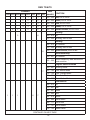
DMX TRAITS
CHANNEL DMX
VALUES FUNCTION
1CH 2CH 3CH 4CH 5CH 6CH 7CH 8CH
1 1 1 1 1 000 - 255 Red, 0% to 100%
2 2 2 2 2 000 - 255 Green, 0% to 100%
3 3 3 3 3 000 - 255 Blue, 0% to 100%
4 4 4 4 4 000 - 255 Amber, 0% to 100%
2 2 5 5 5 5 000 - 255 Master Dimmer, 0% to 100%
3 6
Strobing
000 - 015 O
016 - 255 Strobing, slow to fast
6
Strobing
000 - 015 No Function
016 - 255 Strobing, slow to fast
000 - 255 Speed Control, slow to fast
Sound Sensitivity
000 - 031 No Function
032 - 255 Sound Sensitivity, least sensitive to
most sensitive
7
Program Selection Mode
000 - 051 Dimming Mode
052 - 102 Color Macro Mode
103 - 153 Color Change Mode
154 - 204 Color Fade Mode
205 - 255 Sound Active Mode
111 67
Color Macros
000 - 015 O
016 - 031 Red
032 - 047 Green
048 - 063 Blue
064 - 079 Amber
080 - 095 Red & Green
096 - 111 Red & Blue
112 - 127 Red & Amber
128 - 143 Green & Blue
CONTINUED ON NEXT PAGE

19
DMX TRAITS
CHANNEL DMX
VALUES FUNCTION
1CH 2CH 3CH 4CH 5CH 6CH 7CH 8CH
111 67
Color Macros (continued)
144 - 159 Green & Amber
160 - 175 Blue & Amber
176 - 191 Red, Green, & Blue
192 - 207 Red, Green, & Amber
208 - 223 Red, Blue, & Amber
224 - 239 Green, Blue, & Amber
240 - 255 Red, Green, Blue, & Amber
8
Color Macro Mode
000 - 015 O
016 - 031 Red
032 - 047 Green
048 - 063 Blue
064 - 079 Amber
080 - 095 Red & Green
096 - 111 Red & Blue
112 - 127 Red & Amber
128 - 143 Green & Blue
144 - 159 Green & Amber
160 - 175 Blue & Amber
176 - 191 Red, Green, & Blue
192 - 207 Red, Green, & Amber
208 - 223 Red, Blue, & Amber
224 - 239 Green, Blue, & Amber
240 - 255 Red, Green, Blue, & Amber
Color Change Mode
000 - 015 Color Change 1
016 - 031 Color Change 2
032 - 047 Color Change 3
048 - 063 Color Change 4
064 - 079 Color Change 5
080 - 095 Color Change 6
CONTINUED ON NEXT PAGE

20
DMX TRAITS
CHANNEL DMX
VALUES FUNCTION
1CH 2CH 3CH 4CH 5CH 6CH 7CH 8CH
8
Color Change Mode (continued)
096 - 111 Color Change 7
112 - 127 Color Change 8
128 - 143 Color Change 9
144 - 159 Color Change 10
160 - 175 Color Change 11
176 - 191 Color Change 12
192 - 207 Color Change 13
208 - 223 Color Change 14
224 - 239 Color Change 15
240 - 255 Color Change 16
Color Fade Mode
000 - 015 Color Fade 1
016 - 031 Color Fade 2
032 - 047 Color Fade 3
048 - 063 Color Fade 4
064 - 079 Color Fade 5
080 - 095 Color Fade 6
096 - 111 Color Fade 7
112 - 127 Color Fade 8
128 - 143 Color Fade 9
144 - 159 Color Fade 10
160 - 175 Color Fade 11
176 - 191 Color Fade 12
192 - 207 Color Fade 13
208 - 223 Color Fade 14
224 - 239 Color Fade 15
240 - 255 Color Fade 16
Sound Active Mode
000 - 015 Sound Active Mode 1
016 - 031 Sound Active Mode 2
032 - 047 Sound Active Mode 3
CONTINUED ON NEXT PAGE
Page is loading ...
Page is loading ...
Page is loading ...
Page is loading ...
Page is loading ...
Page is loading ...
Page is loading ...
Page is loading ...
Page is loading ...
Page is loading ...
-
 1
1
-
 2
2
-
 3
3
-
 4
4
-
 5
5
-
 6
6
-
 7
7
-
 8
8
-
 9
9
-
 10
10
-
 11
11
-
 12
12
-
 13
13
-
 14
14
-
 15
15
-
 16
16
-
 17
17
-
 18
18
-
 19
19
-
 20
20
-
 21
21
-
 22
22
-
 23
23
-
 24
24
-
 25
25
-
 26
26
-
 27
27
-
 28
28
-
 29
29
-
 30
30


