Page is loading ...

7700 MultiFrame Manual
7736CEM Composite Encoder with Monitoring
Revision 1.5
*Grey background indicates un-implemented or un-tested features
TABLE OF CONTENTS
1. OVERVIEW ....................................................................................................................................... 1
1.1. FUNCTIONAL DESCRIPTION .................................................................................................. 2
2. INSTALLATION ................................................................................................................................. 5
2.1. VIDEO IN AND OUT ................................................................................................................. 5
3. SPECIFICATIONS ............................................................................................................................. 6
3.1. SERIAL VIDEO INPUT ............................................................................................................. 6
3.2. ANALOG BROADCAST VIDEO OUTPUT ................................................................................ 6
3.3. REFERENCE VIDEO INPUT .................................................................................................... 7
3.4. ANALOG MONITORING VIDEO OUTPUT ............................................................................... 7
3.5. ANALOG AUDIO OUTPUTS (-A4 ONLY) ................................................................................. 7
3.6. UNBALANCED AES AUDIO INPUTS (-A4 ONLY) ................................................................... 8
3.7. BALANCED AES AUDIO INPUTS (-A4-B ONLY) .................................................................... 8
3.8. ELECTRICAL ........................................................................................................................... 8
3.9. PHYSICAL ................................................................................................................................ 8
4. STATUS LEDS .................................................................................................................................. 9
4.1. MODULE STATUS LEDS ......................................................................................................... 9
4.2. AUDIO STATUS LEDS ........................................................................................................... 10
5. AUDIO LEVELS, HEADROOM, CLIPPING AND THE BAR GRAPHS ............................................ 11
6. AUDIO ALARM CALIBRATION PROCEDURE ............................................................................... 12
6.1. CALIBRATE AUDIO SILENCE DETECTION .......................................................................... 12
6.2. CALIBRATE AUDIO PHASE REVERSAL DETECTION ......................................................... 12
6.3. CALIBRATE AUDIO MONO DETECTION .............................................................................. 12
6.4. DEFINE THE FAULT CONDITION(S) ..................................................................................... 13

7700 MultiFrame Manual
7736CEM Composite Encoder with Monitoring
Revision 1.5
*Grey background indicates un-implemented or un-tested features
7. ON SCREEN MENUS ...................................................................................................................... 14
7.1. NAGIVATING THE ON SCREEN MENU SYSTEM ................................................................. 14
7.2. CHANGING TEXT FIELDS ..................................................................................................... 14
7.3. ON SCREEN DISPLAY – MAIN MENU .................................................................................. 15
7.4. CONFIGURING THE AUDIO CONTROLS (-A4) .................................................................... 16
7.4.1. Selecting the Audio Source ..................................................................................... 16
7.4.2. Audio Freeze Mode (-A4) ........................................................................................ 17
7.4.3. Additional Audio Delay (-A4) ................................................................................... 17
7.4.4. Monitoring the Audio Buffer Tracking (-A4) ............................................................. 18
7.4.5. Audio Channels Processing (-A4) ........................................................................... 18
7.4.6. Setting the Analog Levels (-A4)............................................................................... 19
7.5. CONFIGURING THE VIDEO AND SOURCE ID CONTROLS ................................................ 19
7.5.1. Setting the Video Standard ..................................................................................... 21
7.5.2. Selects Input Video Lock Mode ............................................................................... 21
7.5.3. Selects the Action to Take when Input Video Is Missing ......................................... 22
7.5.4. Genlock Source Selection ....................................................................................... 22
7.5.5. Setting the Free-Running Frequency ...................................................................... 23
7.5.6. Setting the Fine Phase of the Output Video – NTSC/PAL-M/525 Video .................. 23
7.5.7. Setting the Fine Phase of the Output Video – PAL-B/625 Video ............................. 23
7.5.8. Setting the Horizontal Phase of the Output Video – NTSC/PAL-M/525 Video ......... 24
7.5.9. Setting the Horizontal Phase of the Output Video – PAL-B/625 Video .................... 24
7.5.10. Monitoring the Horizontal Delay between the Input and Output Video ..................... 24
7.5.11. Setting the Vertical Phase of the Output Video – NTSC/525 or PAL-M/525 Video .. 24
7.5.12. Setting the Vertical Phase of the Output Video – PAL-B/625 Video ........................ 24
7.5.13. Monitoring the Vertical Delay between the Input and Output Video ......................... 24
7.5.14. Setting the Colour Field Phase of the Output Video – NTSC Video ........................ 25
7.5.15. Setting the Colour Field Phase of the Output Video – PAL-B Video ........................ 25
7.5.16. Monitoring the Audio Buffer Tracking (-A4) ............................................................. 25
7.5.17. Setting the VITC Line Number – 525 Line Video ..................................................... 26
7.5.18. Setting the VITC Line Number – 625 Line Video ..................................................... 26
7.5.19. Setting the PESA Source ID Line Number – 525 Line Video ................................... 26
7.5.20. Setting the PESA Source ID Line Number – 625 Line Video ................................... 26
7.5.21. Setting the Default SID Mode .................................................................................. 26
7.5.22. Setting the Message to be Displayed When There Is No Incoming SID .................. 27
7.6. CONFIGURING THE VIDEO PROCESSING CONTROLS ..................................................... 27
7.6.1. Adding the NTSC Setup Pedestal ........................................................................... 28
7.6.2. Line 21 Processing ................................................................................................. 28
7.6.3. Colour Bars ............................................................................................................. 28
7.6.4. Setting the Composite Display Mode – Colour or Monochrome .............................. 29
7.6.5. Video Level ............................................................................................................. 29
7.6.6. Setting the Hue ....................................................................................................... 29
7.6.7. Setting the Saturation ............................................................................................. 29
7.6.8. Setting the Contrast ................................................................................................ 29
7.6.9. Setting the Brightness ............................................................................................. 30

7700 MultiFrame Manual
7736CEM Composite Encoder with Monitoring
Revision 1.5
*Grey background indicates un-implemented or un-tested features
7.6.10. H Blanking .............................................................................................................. 30
7.6.11. VBI Blanking ........................................................................................................... 30
7.6.12. Y Filter Selection ..................................................................................................... 30
7.6.13. Wideband Y Frequency Response .......................................................................... 30
7.6.14. Chroma Filter Selection ........................................................................................... 31
7.7. CONFIGURING THE VBI ....................................................................................................... 32
7.7.1. Line Processing ...................................................................................................... 32
7.8. CONFIGURING THE BAR GRAPH CONTROLS ................................................................... 33
7.8.1. Selecting the Bar Graph Operating Mode ............................................................... 33
7.8.2. Setting the Headroom ............................................................................................. 34
7.8.3. Setting the Bar Graph Type .................................................................................... 34
7.8.4. Setting the PPM Mode and Ballistics ....................................................................... 35
7.8.5. Setting the VU Display Range ................................................................................. 35
7.8.6. Setting the Phase Bar Graph Type ......................................................................... 36
7.8.7. Setting the Bar Graph Error Region ........................................................................ 36
7.8.8. Setting the Bar Graph Warning Region ................................................................... 36
7.8.9. Setting the Level Bar Graph Scale Position ............................................................. 36
7.8.10. Setting the Phase Bar Graph Scale Position ........................................................... 37
7.8.11. Setting the Window and Bar Graph Positions ......................................................... 37
7.8.12. Setting the Colours of the Bar Graphs .................................................................... 37
7.8.12.1. Setting the Level Bar Graph Region Colour .......................................... 37
7.8.12.1.1. Selecting a Bar Graph Region Custom Colour ........................ 37
7.8.13. Setting The Level Bar Graph Size ........................................................................... 38
7.8.14. Setting the Transparency (Opacity) of Bar Graph Background ............................... 38
7.8.15. Setting the Transparency (Opacity) of the Bar Graph Bars ..................................... 38
7.9. CONFIGURING THE ON-SCREEN DISPLAY CONTROLS ................................................... 38
7.9.1. Descriptions of the On-Screen Windows ................................................................. 39
7.9.1.1. Video/Audio Status ............................................................................... 39
7.9.1.2. Audio Bar Graphs ................................................................................. 40
7.9.1.3. VITC Time Code Window ..................................................................... 40
7.9.1.4. Program Rating Window ....................................................................... 41
7.9.1.5. CC Window .......................................................................................... 41
7.9.1.6. XDS Window ........................................................................................ 41
7.9.1.7. Source Identification Window ............................................................... 41
7.9.1.8. Fault Message Windows ....................................................................... 41
7.9.2. Setting the Position of On Screen Windows ............................................................ 41
7.9.2.1. Setting the Horizontal Position of On Screen Windows ........................ 42
7.9.2.2. Setting the Vertical Position of On Screen Windows............................. 42
7.9.3. Selecting What Bar Graphs And Windows To Display ............................................ 42
7.9.4. Setting the Text Window Attributes ......................................................................... 42
7.9.4.1. Turning on the Text Window Backgrounds ........................................... 43
7.9.4.2. Setting the Text Window Background Colours ...................................... 43
7.9.4.3. Setting the Text Window Background Opacity ...................................... 43
7.9.4.4. Setting the Text Window Text Opacity .................................................. 43
7.9.4.5. Setting the Time Code Window Font Size ............................................ 44
7.9.4.6. Setting the Program Rating Window Font Size ..................................... 44
7.9.4.7. Setting the Source ID Window Font Size .............................................. 44
7.9.4.8. Setting the Status Window Mode .......................................................... 44

7700 MultiFrame Manual
7736CEM Composite Encoder with Monitoring
Revision 1.5
*Grey background indicates un-implemented or un-tested features
7.9.5. Setting the Fault Window Attributes ........................................................................ 45
7.9.5.1. Turning on the Fault Window Backgrounds .......................................... 45
7.9.5.2. Setting the Fault Window Background Colours..................................... 45
7.9.5.3. Setting the Fault Window Background Opacity ..................................... 45
7.9.5.4. Setting the Fault Window Text Opacity ................................................. 45
7.9.5.5. Setting the Fault Window Font Size ...................................................... 46
7.9.5.6. Setting the Blink Mode of the Fault Windows ....................................... 46
7.10. GPO CONFIGURATION ......................................................................................................... 46
7.10.1. Frame Status Fault Trigger Condition ..................................................................... 46
7.11. FAULT DEFINITIONS ............................................................................................................. 47
7.11.1. Setting Up How a Fault is Triggered and How it is Presented ................................. 49
7.11.1.1. Fault Status .......................................................................................... 49
7.11.1.2. Setting the position of the Fault Windows ............................................. 49
7.11.1.3. Setting the Message Associated with a Fault ....................................... 49
7.11.1.4. Determining If the Fault Message Will Be Displayed ............................ 49
7.11.1.5. Setting the Duration of the Fault Condition ........................................... 49
7.11.1.6. Determining What Items Will Generate the Fault Condition .................. 50
7.11.2. Setting the Fault Window Attributes ........................................................................ 50
7.11.3. Setting the Video Error Duration ............................................................................. 51
7.11.4. Setting the Audio Error Duration ............................................................................. 51
7.11.5. Detecting Audio Over Level Faults .......................................................................... 51
7.11.5.1. Setting the Audio Over Level ................................................................ 51
7.11.5.2. Setting the Audio Over Duration ........................................................... 51
7.11.6. Detecting Audio Silence Faults ............................................................................... 52
7.11.6.1. Setting the Audio Silence Level ............................................................ 52
7.11.6.2. Setting the Audio Silence Duration ....................................................... 52
7.11.7. Detecting Audio Phase Reversal Faults .................................................................. 52
7.11.7.1. Setting the Audio Phase Reversal Level ............................................... 52
7.11.7.2. Setting the Audio Phase Reversal Duration .......................................... 53
7.11.8. Detecting Audio Mono Faults .................................................................................. 53
7.11.8.1. Setting the Audio Mono Threshold Level .............................................. 53
7.11.8.2. Setting the Audio Mono Duration .......................................................... 53
7.11.9. Detecting Loss of Primary Captioning ..................................................................... 54
7.11.10. Detecting Loss of Program Rating Duration ............................................................ 54
7.11.11. Detecting Picture Freeze ......................................................................................... 54
7.11.11.1. Setting the Picture Noise Level ............................................................. 54
7.11.11.2. Setting the Picture Freeze Duration ...................................................... 55
7.11.11.3. Optimizing the Picture Noise Level and Picture Freeze
Duration Parameters ............................................................................ 55
7.11.12. Detecting Picture Black Duration ............................................................................. 56
7.12. UTILITIES ............................................................................................................................... 56
7.12.1. Accessing Information About this Module and its Firmware .................................... 56
7.12.2. Saving and Recalling Configurations....................................................................... 56
7.12.2.1. Storing Configurations to the User Presets ........................................... 56
7.12.2.2. Recall Configurations from the User Presets ........................................ 56
7.12.3. Initiating a Software Upgrade .................................................................................. 57
7.12.4. Restoring the CEM to its Factory Default Configuration .......................................... 57

7700 MultiFrame Manual
7736CEM Composite Encoder with Monitoring
Revision 1.5
*Grey background indicates un-implemented or un-tested features
7.13. CLEAR FAULTS AND PEAKS ............................................................................................... 57
8. VISTALINK® CONFIGURATION ...................................................................................................... 58
8.1. WHAT IS
VISTA
LINK®? ......................................................................................................... 58
8.2. AUDIO SETTINGS .................................................................................................................. 58
8.2.1. Audio Source .......................................................................................................... 59
8.2.2. Audio Freeze Mode ................................................................................................. 59
8.2.3. Audio Delay ............................................................................................................. 59
8.2.4. Audio Buffer ............................................................................................................ 59
8.3. AUDIO BAR GRAPH .............................................................................................................. 60
8.3.1. Bar Graph Size ....................................................................................................... 60
8.3.2. Bars Opacity ........................................................................................................... 61
8.3.3. Background Opacity ................................................................................................ 61
8.3.4. Channel Pairs 1 and 2 ............................................................................................. 61
8.3.4.1. Audio Level Mode ................................................................................. 61
8.3.4.2. Headroom ............................................................................................. 61
8.3.4.3. Level Type ............................................................................................ 61
8.3.4.4. PPM Mode ............................................................................................ 62
8.3.4.5. VU Range ............................................................................................. 63
8.3.4.6. Level Scale Position ............................................................................. 63
8.3.4.7. Coloured Regions ................................................................................. 63
8.3.4.7.1. Setting the Bar Graph Error Region ........................................ 64
8.3.4.7.2. Setting the Bar Graph Warning Region .................................. 65
8.3.5. Phase Type ............................................................................................................. 65
8.3.6. Phase Scale Position .............................................................................................. 65
8.4. AUDIO BAR GRAPH POSITIONS .......................................................................................... 65
8.4.1. Enable ..................................................................................................................... 66
8.4.2. Setting the Horizontal Position of On Screen Windows ........................................... 66
8.4.3. Setting the Vertical Position of On Screen Windows ............................................... 66
8.5. FAULT SETTINGS .................................................................................................................. 66
8.5.1. Loss of Video Duration ............................................................................................ 67
8.5.2. Loss of Audio Duration ............................................................................................ 67
8.5.3. Audio Over Level ..................................................................................................... 67
8.5.4. Audio Over Duration ................................................................................................ 67
8.5.5. Audio Silence Level ................................................................................................. 67
8.5.6. Audio Silence Duration ............................................................................................ 67
8.5.7. Audio Phase Reversal Level ................................................................................... 67
8.5.8. Audio Phase Reversal Duration .............................................................................. 68
8.5.9. Audio Mono Threshold Level ................................................................................... 68
8.5.10. Audio Mono Duration .............................................................................................. 68
8.5.11. Loss of Closed Captioning Duration ........................................................................ 68
8.5.12. Loss of Program Rating Duration ............................................................................ 68
8.5.13. Picture Freeze Duration .......................................................................................... 68
8.5.14. Picture Black Duration ............................................................................................. 68
8.6. AUDIO CHANNELS ................................................................................................................ 69

7700 MultiFrame Manual
7736CEM Composite Encoder with Monitoring
Revision 1.5
*Grey background indicates un-implemented or un-tested features
8.6.1. Channel Output Select ............................................................................................ 69
8.6.2. Analog Output Level ............................................................................................... 69
8.7. FAULT CONDITIONS ............................................................................................................. 70
8.7.1. Mode ....................................................................................................................... 70
8.7.2. Message ................................................................................................................. 70
8.7.3. Duration .................................................................................................................. 70
8.7.4. Determining What Items Will Generate the Fault Condition .................................... 71
8.8. VIDEO AND SID ..................................................................................................................... 72
8.8.1. Video Standard ....................................................................................................... 72
8.8.2. Loss of Video .......................................................................................................... 73
8.8.3. Genlock Source ...................................................................................................... 73
8.8.4. Free-Running Frequency ........................................................................................ 73
8.8.5. Fine Phase 525 ....................................................................................................... 73
8.8.6. Fine Phase 625 ....................................................................................................... 73
8.8.7. NTSC Colour Phase................................................................................................ 74
8.8.8. PAL-B Colour Phase ............................................................................................... 74
8.8.9. Video Lock Mode .................................................................................................... 74
8.8.10. VITC 525 ................................................................................................................. 74
8.8.11. VITC 625 ................................................................................................................. 74
8.8.12. PESA 525 ............................................................................................................... 74
8.8.13. PESA 625 ............................................................................................................... 75
8.8.14. Default SID Mode .................................................................................................... 75
8.8.15. Default SID Message .............................................................................................. 75
8.9. FAULT WINDOWS ................................................................................................................. 75
8.9.1. Text ......................................................................................................................... 76
8.9.2. Background Colour ................................................................................................. 76
8.9.3. Text Opacity ............................................................................................................ 76
8.9.4. Background Opacity ................................................................................................ 76
8.9.5. Setting the Horizontal Position of the Fault Windows .............................................. 76
8.9.6. Setting the Vertical Position of the Fault Windows .................................................. 76
8.9.7. Setting the Fault Window Font Size ........................................................................ 76
8.9.8. Setting the Blink Mode of the Fault Windows .......................................................... 77
8.10. FAULT TRAPS ....................................................................................................................... 77
8.11. VIDEO CONTROLS ................................................................................................................ 78
8.11.1. NTSC Setup Pedestal ............................................................................................. 78
8.11.2. Line 21 Setup Pedestal ........................................................................................... 78
8.11.3. Composite Display Mode ........................................................................................ 79
8.11.4. Video Level ............................................................................................................. 79
8.11.5. Hue ......................................................................................................................... 79
8.11.6. Saturation ............................................................................................................... 79
8.11.7. Contrast .................................................................................................................. 79
8.11.8. Brightness ............................................................................................................... 79
8.11.9. H Blanking .............................................................................................................. 79
8.11.10. VBI Processing ....................................................................................................... 79
8.11.11. Y Filter Selection ..................................................................................................... 79
8.11.12. Wideband Y Frequency Response .......................................................................... 80

7700 MultiFrame Manual
7736CEM Composite Encoder with Monitoring
Revision 1.5
*Grey background indicates un-implemented or un-tested features
8.11.13. Chroma Filter Selection ........................................................................................... 80
8.12. WINDOW SETTINGS ............................................................................................................. 80
8.12.1. Text ......................................................................................................................... 81
8.12.2. Background Colour ................................................................................................. 81
8.12.3. Text Opacity ............................................................................................................ 81
8.12.4. Background Opacity ................................................................................................ 81
8.12.5. Status Window ........................................................................................................ 81
8.12.5.1. Setting the Horizontal Position of the Status Window ........................... 81
8.12.5.2. Setting the Vertical Position of the Status Window ............................... 81
8.12.5.3. Mode .................................................................................................... 82
8.12.6. VITC Window .......................................................................................................... 82
8.12.6.1. Setting the Horizontal Position of the VITC Window ............................. 82
8.12.6.2. Setting the Vertical Position of the VITC Window ................................. 82
8.12.6.3. Size ...................................................................................................... 82
8.13. GENERAL .............................................................................................................................. 82
8.13.1. Frame Status Trigger .............................................................................................. 83
8.13.2. Card Type ............................................................................................................... 83
9. JUMPERS ....................................................................................................................................... 84
9.1. TERMINATION JUMPERS ..................................................................................................... 84
9.2. SELECTING WHETHER LOCAL FAULTS WILL BE MONITORED BY THE GLOBAL
FRAME STATUS .................................................................................................................... 84
9.3. CONFIGURING THE MODULE FOR FIRMWARE UPGRADES ............................................ 84
Figures
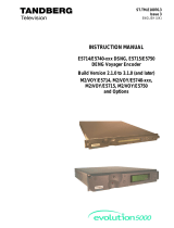
Figure 1-1: 7736CEM-A4 Block Diagram .............................................................................................................. 3
Figure 1-2: 7736CEM Block Diagram .................................................................................................................... 3
Figure 1-3: 7736CEM-A4-B Block Diagram ........................................................................................................... 4
Figure 2-1: 7736CEM Rear Panels ........................................................................................................................ 5
Figure 4-1: LED Locations ..................................................................................................................................... 9
Figure 8-1: Audio Settings Tab ............................................................................................................................ 58
Figure 8-2: Audio Bar Graph Tab ........................................................................................................................ 60
Figure 8-3: Swatches Window ............................................................................................................................. 63
Figure 8-4: HSB Window ..................................................................................................................................... 64
Figure 8-5: RBG Window ..................................................................................................................................... 64
Figure 8-6: Audio Bar Graph Positions Tab ......................................................................................................... 65
Figure 8-7: Fault Settings Tab ............................................................................................................................. 66
Figure 8-8: Audio Channels Tab .......................................................................................................................... 69
Figure 8-9: Fault Conditions Tab ......................................................................................................................... 70
Figure 8-10: Video and SID Tab .......................................................................................................................... 72
Figure 8-11: Fault Windows Tab ......................................................................................................................... 75
Figure 8-12: Fault Traps Tab ............................................................................................................................... 77
Figure 8-13: Video Controls Tab .......................................................................................................................... 78
Figure 8-14: Window Settings Tab ...................................................................................................................... 80
Figure 8-15: General Tab .................................................................................................................................... 82

7700 MultiFrame Manual
7736CEM Composite Encoder with Monitoring
Revision 1.5
*Grey background indicates un-implemented or un-tested features
Tables
Table 4-1: Audio Channel Status LEDs ............................................................................................................... 10
Table 7-1: PPM Bar Graph Characteristics ......................................................................................................... 35
Table 7-2: Video/Audio Status Screen Items....................................................................................................... 40
Table 7-3: Methods of Turning Windows and Bar Graphs On and Off ............................................................... 42
Table 7-4: Possible Error Conditions to Produce a Fault .................................................................................... 50
Table 8-1: PPM Bar Graph Characteristics ......................................................................................................... 62

7700 MultiFrame Manual
7736CEM Composite Encoder with Monitoring
Revision 1.5
*Grey background indicates un-implemented or un-tested features
REVISION HISTORY
REVISION
DESCRIPTION
DATE
0.0
Preliminary
Feb 2004
1.0
First Release
Jun 2004
1.1
Balanced audio version added
Oct 2004
1.2
1.3
Remove references to GPIs
Added warning to Colour bar control
Fixed minor items
Updated formatting
July 20
05
Dec 2009
1.4 Input lock modes added, PAL-M support added, Line-by-line
Setup pedestal control added
May 2011
1.5
Added VistaLINK Configuration section
June 2012
Please Note: This version contains areas of gray text that are indicative of future
software releases. These sections are to be used as information only and are subject
to change. Some features will never be released. Some of these features may seem to
work but they have not been completed and have not been verified by Evertz.
Information contained in this manual is believed to be accurate and reliable. However, Evertz assumes no responsibility for the use thereof nor for
the rights of third parties, which may be affected in any way by the use thereof. Any representations in this document concerning performance of
Evertz products are for informational use only and are not warranties of future performance, either expressed or implied. The only warranty
offered by Evertz in relation to this product is the Evertz standard limited warranty, stated in the sales contract or order confirmation form.
Although every attempt has been made to accurately describe the features, installation and operation of this product in this manual, no warranty
is granted nor liability assumed in relation to any errors or omissions unless specifically undertaken in the Evertz sales contract or order
confirmation. Information contained in this manual is periodically updated and changes will be incorporated into subsequent editions. If you
encounter an error, please notify Evertz Customer Service department. Evertz reserves the right, without notice or liability, to make changes in
equipment design or specifications.

7700 MultiFrame Manual
7736CEM Composite Encoder with Monitoring
Revision 1.5
*Grey background indicates un-implemented or un-tested features
This page left intentionally blank

7700 MultiFrame Manual
7736CEM Composite Encoder with Monitoring
Revision 1.5 Page - 1
*Grey background indicates un-implemented or un-tested features
1. OVERVIEW
The 7736CEM line of component serial digital to composite analog video converters are broadcast quality
encoders with an extensive list of additional features. An audio de-embedder with high quality audio digital
to analog conversion can be purchased with the encoder to create a video/audio frame
synchronizer/conversion package. In addition, Evertz fault monitoring processing will analyze and report
video and audio problems via an On-Screen-Display (OSD), or remotely via VistaLINK® SNMP.
The 7736CEM product features various video processing functions such as VITC, closed captioning and
SID extraction during the encoding process, as well as monitoring video for black and freeze conditions.
The audio is processed, to extract level information for creating and displaying level and phase bar
graphs. In addition, the audio is analyzed for periods of high level, silence, mono, and out-of-phase
conditions. All of this status information is displayed on the monitoring analog output via on-screen display
(OSD) overlay.
The Features of all 7736CEM’s are:
• One component serial digital input (525 or 625).
• One re-clocked component serial digital output.
• EDH analysis on SDI input.
• Four composite analog video outputs WITHOUT OSD text or audio bargraphs.
• Internal processing to maintain 10 bit digital video quality.
• 10 bit output video digital to analog conversion.
• One monitoring quality video output with OSD text and bargraph graphics.
• User adjustable output video processing functions: black level (brightness), gain (contrast), hue,
and saturation.
• User selectable luminance and chrominance filters for different applications (i.e. broadcast vs.
studio).
• User selectable horizontal blanking interval width: narrow, normal.
• One composite analog reference input (NTSC or PAL-B) on BNC. 75 Ohm or high-Z, jumper
configurable input impedance.
• One frame video synchronizer (with +S option).
• Infinitely variable output phase.
• Freeze modes: black, freeze.
• Adjustable free running frequency.
• Built-in colour bar generator.
• VU/PPM bargraph level Indicators.
• Decodes vertical interval time code (VITC) and “burns” the time code into the picture.
• Decodes PESA format Source ID (8 characters) or Evertz format VITC Source ID (5 or 9
characters) and burns the ID into the picture.
• A comprehensive on screen display is available to configure the various features of the module.
• Flexible configuration of the text and audio bar graph information displays.
• An extensive list of error conditions can be monitored and fault conditions can be configured from
these conditions.
• On screen messages can be triggered by the configured fault conditions.

7700 MultiFrame Manual
7736CEM Composite Encoder with Monitoring
Page - 2 Revision 1.5
*Grey background indicates un-implemented or un-tested features
The Features of "-A4" Options are:
• One group (4 channels) of synchronous 20-bit audio is de-multiplexed from the incoming digital
video.
• 2 unbalanced (or balanced) AES audio inputs (up to 48kHz, 24 bits) on BNC (terminal strip).
• User selects EITHER the de-embedded audio or the input AES audio.
• The selected audio is delayed equivalently to the video delay with the +S option.
• 4 high quality 24 bit audio channels are output (analog) as balanced on 2 removable barrier strips.
• Low impedance outputs (66Ω).
• Analog audio output levels are adjustable.
• Additional audio delay of up to 5 seconds.
• Additional audio advance of up to 1 frame, depending on video delay.
• Loss of video modes: pass audio, mute audio.
1.1. FUNCTIONAL DESCRIPTION
270Mbps component SDI video is converted to 10 bit parallel data and encoded to high quality composite
analog video. Various video processing functions (gain, saturation, black level, etc) are performed during
the encoding process.
A re-clocked copy of the component SDI video is available on the “SDI OUT” BNC. This output will not be
present if the card is unplugged or the power to the frame is turned off.
Digital audio is de-multiplexed from the incoming SDI video. External digital AES audio is also received via
input BNC's (unbalanced) or removable terminal strip (balanced). The user can select either of these two
sources for further processing. The selected digital audio is delayed (with +S option) to match the delay
experienced by the video in the video synchronizer. In addition, the user can select additional audio delay.
On the 7736CEM-A4, the audio is converted to balanced analog audio through a high quality 24 bit D to A
converter and delivered to the outside world via removable terminal strips.
The audio is also processed to extract level and phase information. The CPU creates the level and phase
bar graphs and writes them out to the on screen display (OSD) memory.
VITC, closed captioning and Source ID are extracted from this input stream. In addition, the video is
monitored for black and freeze conditions. The CPU reads this raw data and extracts time code, program
rating and the closed captioning information. In addition, analysis of the data is performed to determine
fault or error conditions. The time code, program rating, source ID message and faults are also written to
the OSD memory for display on the monitoring output.
This video goes out through two paths; a high quality component to composite converter (composite
encoder) and a monitoring quality composite encoder with the OSD "burn-ins". The hardware mixes
(keys) the on screen text and bar graphs display information onto the monitoring output video stream.
The CPU also gets pushbutton and toggle switch commands from the card edge controls and draws
extensive menus for configuring the operation of the card.

7700 MultiFrame Manual
7736CEM Composite Encoder with Monitoring
Revision 1.5 Page - 3
*Grey background indicates un-implemented or un-tested features
Composite
Outputs
2 AES
Inputs
EDH
Analysis
Monitoring
Quality
Composite
Encoder
Mon Output
SDI Input
VBI Decoders
and Freeze/
Black detector
Genlock
75Ω
Card
Reference
CPU
Card Edge
Controls &
Indicators
To/From
SNMP
Network
Composite
Analog
Reference
OSD
Display
Audio content
analysis and
Delay (optional)
High
Quality
Composite
Encoder
Audio
Demux
Frame
Sync
(optional)
AES
Receivers
D/A
4 Channels
Balanced
Analog
Audio
Reclocked
SDI Out
S/P
Figure 1-1: 7736CEM-A4 Block Diagram
Composite
Outputs
EDH
Analysis
Monitoring
Quality
Composite
Encoder
Mon Output
SDI Input
VBI Decoders
and Freeze/
Black detector
Genlock
75Ω
Card
Reference
CPU
Card Edge
Controls &
Indicators
To/From
SNMP
Network
Composite
Analog
Reference
OSD
Display
High
Quality
Composite
Encoder
Frame
Sync
(optional)
Reclocked
SDI Out
S/P
Figure 1-2: 7736CEM Block Diagram

7700 MultiFrame Manual
7736CEM Composite Encoder with Monitoring
Page - 4 Revision 1.5
*Grey background indicates un-implemented or un-tested features
Composite
Outputs
2 AES
Inputs
EDH
Analysis
Monitoring
Quality
Composite
Encoder
Mon Output
SDI Input
VBI Decoders
and Freeze/
Black detector
Genlock
75Ω
Card
Reference
CPU
Card Edge
Controls &
Indicators
To/From
SNMP
Network
Composite
Analog
Reference
OSD
Display
Audio content
analysis and
Delay (optional)
High
Quality
Composite
Encoder
Audio
Demux
Frame
Sync
(optional)
AES
Receivers
D/A
4 Channels
Balanced
Analog
Audio
Reclocked
SDI Out
S/P
(balanced)
Figure 1-3: 7736CEM-A4-B Block Diagram

7700 MultiFrame Manual
7736CEM Composite Encoder with Monitoring
Revision 1.5 Page - 5
*Grey background indicates un-implemented or un-tested features
2. INSTALLATION
The 7736CEM modules come with a companion rear plate and occupy one or two slots in the 7700FR
frame.
Figure 2-1 shows a picture of each of the rear panels. For information on mounting the rear plate and
inserting the module into the frame see the 7700FR chapter section 3.
The 7736CEM cards must be inserted into slots with the correct rear panel. Some cards have physical
differences and some have functional differences and the associated labels will be misleading.
Figure 2-1: 7736CEM Rear Panels
2.1. VIDEO IN AND OUT
Connect a source of component serial digital (525 or 625 line) video to the top BNC labeled SDI IN. A re-
clocked version of the input video is available on the SDI OUT BNC. Connect a reference black signal to
the REF IN BNC if frame synchronization is desired (+S only). Broadcast quality composite analog video
is available on the ANALOG OUT BNCs. Monitoring quality video with text and audio bar graphs are
available on the MON OUT output BNC. If the card is not present or the power is off, there will be nothing
on any of the outputs.

7700 MultiFrame Manual
7736CEM Composite Encoder with Monitoring
Page - 6 Revision 1.5
*Grey background indicates un-implemented or un-tested features
3. SPECIFICATIONS
3.1. SERIAL VIDEO INPUT
Standard:
SMPTE 259M-C – 525 or 625 line component
Number of Inputs:
1
Number of Re-
Clocked Outputs:
1
Connector:
BNC per IEC 169-8
Return Loss:
>15dB to 270MHz
Embedded Audio:
SMPTE 272M-A
Frequency Lock
Range:
±75ppm from nominal
Lock Up Time on a
Hot Switch:
TBD
3.2. ANALOG BROADCAST VIDEO OUTPUT
Standard:
NTSC, SMPTE 170M
PAL, ITU624-4
PAL-M
Number of Outputs:
4
Connector:
BNC per IEC 169-8
Signal Level:
1V nominal
Output Impedance:
75 Ohm
DC Offset:
0V +/- 50mV
Return Loss:
>45dB to 10MHz
Frequency Response:
<+/- 0.1dB to 4 MHz (response will depend on selected filtering)
Differential Phase:
< 0.5° (< 0.3° typical)
Differential Gain:
< 0.5% (< 0.3% typical)
SNR:
>75dB (black video, 100kHz to 5MHz)
Output Level Control Range:
±10%
Black Level Control Range:
±7.5 IRE
Chroma Level Control Range:
±10%
Hue Control Range:
±15 deg. (NTSC only)
Minimum Delay:
3 µs
Maximum Delay:
1 frame + 3 µs (+S option only)

7700 MultiFrame Manual
7736CEM Composite Encoder with Monitoring
Revision 1.5 Page - 7
*Grey background indicates un-implemented or un-tested features
3.3. REFERENCE VIDEO INPUT
Standard:
NTSC, SMPTE 170M
PAL, ITU624-4
Number of Inputs:
1
Connector:
BNC per IEC 169-8
Signal Level:
1V nominal (0.5V to 1.5V)
Frequency Lock Range:
±75ppm from nominal
Input Impedance:
75 Ohm or High impedance (jumper selectable)
Return Loss:
>25dB to 10MHz
Max Subcarrier Jitter:
< 3 degrees
Free-Running
Frequency Control
Range:
> +/- 10ppm (> +/- 270Hz)
3.4. ANALOG MONITORING VIDEO OUTPUT
Standard:
NTSC, SMPTE 170M
PAL, ITU624-4
PAL-M
Number of Outputs:
1
Connector:
BNC per IEC 169-8
Signal Level:
1V nominal
Output Impedance:
75 Ohm
Return Loss:
>35dB to 10MHz
3.5. ANALOG AUDIO OUTPUTS (-A4 ONLY)
Number of Outputs:
4
Type:
Balanced analog audio
Connector:
Two 6 pin removable terminal strips
Output Impedance:
66Ω balanced
Sampling Frequency:
48kHz
Signal Level:
0dBFS => 12 to 25dBu (user settable)
Frequency Response:
<+/- 0.05dB (20Hz to 20kHz)
Dynamic Range:
24 bits when AES inputs selected,
20 bits when embedded audio selected
THD+N:
<0.001% (>100dB) @ 1kHz, -1dBFS
Crosstalk:
<-105dB (20Hz to 20kHz)
DC Offset:
<+/- 30mV
SNR:
>110dB "A" Weighting
Inter-Channel Phase
Error:
<+/-1° (20Hz to 20kHz)

7700 MultiFrame Manual
7736CEM Composite Encoder with Monitoring
Page - 8 Revision 1.5
*Grey background indicates un-implemented or un-tested features
3.6. UNBALANCED AES AUDIO INPUTS (-A4 ONLY)
Number of Inputs:
2
Input Standard:
SMPTE 276M, single ended synchronous or asynchronous
PCM AES
Connectors:
BNC per IEC 169-8
Resolution:
Up to 24 bits
Input Sampling Rate:
32kHz to 48 kHz
Minimum I/O Delay:
3.5msec
3.7. BALANCED AES AUDIO INPUTS (-A4-B ONLY)
Number of Inputs:
2
Input Standard:
AES3-1992, balanced synchronous or asynchronous PCM AES
Connectors:
One 6 pin removable terminal strip
Impedance:
110 Ohm
Resolution:
Up to 24 bits
Sampling Rate:
32kHz to 48 kHz
Input Level:
2V to 7V p-p
Minimum I/O
Delay:
3.5msec
3.8. ELECTRICAL
Voltage:
+ 12VDC
Power:
9.25 Watts (7736CEM)
16.75 Watts (-A4 or –A4-B option)
EMI/RFI:
Complies with FCC Part 15, class A and EU EMC directive
3.9. PHYSICAL
7700 Frame Mounting:
Number of
Slots:
1 for non-audio versions
2 for audio version (-A4, -A4-B)

7700 MultiFrame Manual
7736CEM Composite Encoder with Monitoring
Revision 1.5 Page - 9
*Grey background indicates un-implemented or un-tested features
4. STATUS LEDS
7736CEM-A4
toggle
switch push
button
GENLOCK
AUDIO
NTSC
PAL
OK
FAULT 1 2 3 4
Audio LEDs
Figure 4-1: LED Locations
4.1. MODULE STATUS LEDS
MODULE OK:
This Green LED will be on when the module is operating properly.
LOCAL FAULT:
This Red LED makes it easy to identify one module in a frame that is missing an
essential input or has another fault.
The LED will blink on and off if the microprocessor is not running.
The LED will be on when there is a fault in the module power supply or a user
configurable error condition exists.
NTSC/PAL:
The NTSC/PAL Green LEDs (NTSC on the top, away from the PCB and PAL on
the bottom, closest to the PCB) will indicate the video standard of the SDI video
input. If video is removed, both LEDs will go off. The NTSC LED will illuminate
when PAL-M video mode is selected and video is applied. If the input standard is
opposite to the user selected standard, the LED will flash.
GENLOCKED:
This Green LED is on solid if the genlock source is present and the user has
turned on genlocking.
It is flashing if the user has turned on genlocking and the genlock source is not
present.
It will be off if the user has turned genlocking off.
AUDIO:
This Green LED is on solid when the user selected audio is present. It will flash
when some, but not all, of the audio channels are present. If no audio is present,
it will be off.
For instance, if external AES audio is selected (via. the OSD menu) and only
one of the two AES channels is present, then this LED will flash.

7700 MultiFrame Manual
7736CEM Composite Encoder with Monitoring
Page - 10 Revision 1.5
*Grey background indicates un-implemented or un-tested features
4.2. AUDIO STATUS LEDS
Four LEDs located on the lower end of the module (near the card extractor) indicate which audio channels
are present. Audio channel 1 LED is located closest to the center of the module. Digital audio presence is
determined by the AES receiver lock indicator (when AES input is selected). When embedded audio is
selected, the channel must be present on the selected group for the LED to illuminate.
Audio
LED
Colour Audio Channel Status
1
Off
No channel 1 present.
Green
Channel 1 present.
2
Off
No channel 2 present.
Green
Channel 2 present.
3
Off
No channel 3 present.
Green
Channel 3 present.
4
Off
No channel 4 present.
Green
Channel 4 present.
Table 4-1: Audio Channel Status LEDs
/